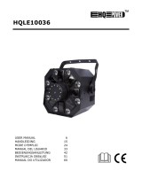
HQ Power EXPLIO I User manual

Category
Stroboscopes & disco lights
Type
User manual

This manual is also suitable for

VDPL1803MHRGB
V. 01 – 26/10/2012 2 ©Velleman nv
terminator
eindweerstand
résistance de terminaison
terminación
Terminierung
How to turn the controller line from 3-pins into 5-pins (plug and socket).
Controller line van 3-pin naar 5-pin aanpassen (stekker en contact).
Modifier la ligne du contrôleur de 3 broches en 5 broches (fiche et contact).
Modificar la línea del controlador de 3 polos y 5 polos (conector y contacto).
Die Controller-Linie von 3-Pin nach 5-Pin anzupassen (Stecker und Kontakt).
V.
1
.
T
o
I
m
Th
If
t
2
.
3
.
Re
01 – 26/10/2
.
Intr
o
o
all reside
n
m
portant e
n
This
har
m
shou
distri
If in
ank you for
t
he device
w
.
Safe
t
This devic
e
qualified p
Make sure
Do not cri
m
necessary
.
Use an ap
p
Install the
substance
s
Respect a
The maxi
m
The maxi
m
.
Gen
e
fer to the V
e
012
o
duction
n
ts of the
E
n
vironmen
t
symbol on t
h
m
the enviro
n
ld be taken
t
butor or to
a
doubt, co
n
choosing H
Q
w
as damage
d
t
y Instr
u
Be very c
a
electrosh
o
Always di
s
activities
a
Indoor u
s
Keep this
Caution:
Do not s
t
epilep
temp
o
perm
a
There are
and/or sp
a
e
falls unde
r
erson carry
that the av
a
m
p the pow
e
.
p
ropriate sa
f
VDPL1803
M
s
.
minimum di
m
um ambien
m
um surface
e
ral Gui
d
e
lleman®
S
Keep this
d
Protect th
i
E
uropean U
n
t
al informa
t
h
e device o
r
n
ment. Do n
t
o a speciali
a
local recy
c
n
tact your l
Q
Power™! P
l
d
in transit,
u
ctions
a
reful durin
g
o
cks.
s
connect m
a
a
re perform
e
s
e only. Ke
e
device awa
y
device heat
s
t
are directl
y
tic seizure i
n
o
rarily loss o
a
nent (irrev
e
no user-ser
a
re parts.
r
protection
c
out the ele
c
a
ilable volta
g
e
r cord and
p
f
ety cable t
o
M
HRGB at a
m
stance of 0.
t temperatu
temperatu
r
d
elines
S
ervice an
d
d
evice awa
y
i
s device fro
VD
P
USE
n
ion
t
ion about
t
r
the packag
ot dispose
o
zed compan
c
ling service
.
ocal waste
l
ease read t
h
don't install
g
the install
a
a
ins power
w
e
d. Handle t
e
p this devi
c
y
from child
r
s
up during
y
at the lig
n
sensitive
p
f sight (flas
h
e
rsible) eye
d
viceable pa
r
c
lass I. It is
c
tric connect
g
e does not
p
rotect it ag
o
fix the dev
i
m
inimal dis
t
5 m betwee
re is 40 °C.
r
e is 50 °C.
d
Q
uality
W
y
from dust
a
m shocks a
n
P
L1803MH
R
3
R MA
N
t
his produ
c
e indicates
t
o
f the unit (
o
y for recycli
.
Respect th
e
disposal a
h
e manual t
h
or use it an
a
tion: touchi
w
hen device
he power c
o
c
e away for
m
r
en and una
u
use.
ht source,
a
p
eople
h
blindness)
d
amage.
r
ts inside th
e
therefore e
s
ion.
exceed the
ainst dama
g
i
ce (e.g. VD
L
t
ance of 0.2
n the devic
e
Do not ope
r
W
arranty on
a
nd extrem
e
n
d abuse. A
v
R
GB
N
UAL
c
t
t
hat disposa
o
r batteries)
ng. This de
v
e
local envi
r
uthorities.
h
oroughly b
e
d contact y
o
ng live wire
s
not in use o
o
rd by the pl
m
rain, mois
u
thorized us
a
s this may
e
device. Re
f
s
sential that
voltage sta
t
g
e. Have an
L
SC7N or V
D
m from fla
m
e
’s light out
p
r
ate the dev
the last pa
g
e
temperatu
r
v
oid brute f
o
l of the devi
as unsorte
d
v
ice should
b
r
onmental r
u
e
fore bringi
n
o
ur dealer.
s
can cause
r when serv
i
ug only.
ture, splash
ers.
cause
f
er to an au
t
the device
b
t
ed in the sp
authorised
d
D
LSC8N).
m
mable and
e
p
ut and any
i
ice at highe
r
g
es of this
m
r
es.
o
rce when o
p
ce after its l
d
municipal
w
b
e returned
t
u
les.
n
g this devi
c
life-threate
n
i
cing or mai
n
ing and drip
t
horized dea
b
e earthed.
ecifications
d
ealer repla
c
explosive o
b
i
lluminated
s
r
temperatu
r
m
anual.
p
erating the
©Vellema
n
ifecycle cou
l
w
aste; it
t
o your
c
e into servi
c
n
ing
n
tenance
ping liquids
.
ler for servi
c
Have a
of this man
u
c
e it if
b
jects or
s
urface.
r
es.
device.
n
nv
l
d
c
e.
.
c
e
u
al.
VDPL1803MHRGB
V. 01 – 26/10/2012 4 ©Velleman nv
Familiarise yourself with the functions of the device before actually using it. Do not allow operation by
unqualified people. Any damage that may occur will most probably be due to unprofessional use of the
device.
All modifications of the device are forbidden for safety reasons. Damage caused by user modifications to
the device is not covered by the warranty.
Only use the device for its intended purpose. All other uses may lead to short circuits, burns, electroshocks,
lamp explosion, crash, etc. Using the device in an unauthorised way will void the warranty.
Damage caused by disregard of certain guidelines in this manual is not covered by the warranty and the
dealer will not accept responsibility for any ensuing defects or problems.
Mechanical wear and LEDs are not covered by warranty.
A qualified technician should install and service this device.
Do not switch the device on immediately after it has been exposed to changes in temperature. Protect the
device against damage by leaving it switched off until it has reached room temperature.
This device is designed for professional use on stage, in discos, theatres, etc. The VDPL1803MHRGB should
only be used indoors with an alternating current of 230 VAC/50 Hz.
Lighting effects are not designed for permanent operation: regular operation breaks will prolong their lives.
Use the original packaging if the device is to be transported.
Keep this manual for future reference.
4. Features
small and light LED moving head, only 3.9 kg
runs extremely fast, with very bright output
suitable for clubs, stage, decoration, etc.
master/slave and sound control modes
DMX controlled by 5, 7, 9, or 12 channels
pan (504°/630°) and tilt (240°), self-correcting
very smooth dimming, narrow punchy beam
blue LCD display for easy configuration, auto switch off after 5 sec.
5. Overview
Refer to the illustrations on page 2 of this manual.
1 display 5 DMX input
2 control buttons 6 DMX output
3 power input 7 safety cable attachment point
4 power output
6. Installation
Choose a suitable mounting spot. Mount the fixture in the desired angle using the included bracket. Connect the
power cord to the mains. Disconnect after use.
Mounting the Device
Have the device installed by a qualified person, respecting EN 60598-2-17 and all other applicable norms.
The carrying construction must be able to support 10 times the weight of the device for 1 hour without
deforming.
The installation must always be secured with a secondary attachment e.g. a safety cable.
Never stand directly below the device when it is being mounted, removed or serviced. Have a qualified
technician check the device once a year and once before you bring it into service.
Install the device in a location with few passers-by that is inaccessible to unauthorised persons.
Overhead mounting requires extensive experience: calculating workload limits, determining the installation
material to be used… Have the material and the device itself checked regularly. Do not attempt to install
the device yourself if you lack these qualifications as improper installation may result in injuries.
For truss mounting, use an appropriate clamp (not incl.) and fit an M10 bolt through the centre of the
(folded) bracket.
Adjust the desired inclination angle via the mounting bracket and tighten the bracket screws.
Make sure there is no flammable material within a 0.2 m radius of the device.
Have a qualified electrician carry out the electric connection.
VDPL1803MHRGB
V. 01 – 26/10/2012 5 ©Velleman nv
Connect the device to the mains with the power plug. Do not connect it to a dimming pack.
The VDPL1803MHRGB has a power output [4] to supply power to another VDPL1803MHRGB. When
connecting several VDPL1803MHRGBs in a daisy chain via this output, make sure that the total current does
not exceed the power line’s nominal current. Use power cables with an adequate section.
The installation has to be approved by an expert before the device is taken into service.
DMX-512 Connection
When applicable, connect an XLR cable to the female 3-pin XLR output of a controller (not incl.) and the
other side to the male 3-pin XLR input [2] of the VDPL1803MHRGB. Multiple VDPL1803MHRGBs can be
linked through serial linking. The linking cable should be a dual core, screened cable with XLR input and
output connectors.
Maximum recommended serial data link distance is 500 meters (1640 ft). Maximum recommended number
of fixtures on a serial data link is 32 fixtures.
A DMX terminator is recommended for installations where the DMX cable has to run a long distance or is in
an electrically noisy environment (e.g. discos). The terminator prevents corruption of the digital control
signal by electrical noise. The DMX terminator is simply an XLR plug with a 120 resistor between pins 2
and 3, which is then plugged into the XLR output socket [1] of the last device in the chain.
7. Operation
The VDPL1803MHRGB can be used in the following modes:
stand-alone mode: automatic or sound-activated
master/slave
with a DMX512 controller.
7.1 Control Panel Navigation
Access the control panel functions using the four panel buttons [11] located directly underneath the
display [10]. From left to right:
Button Function
<SET/ESC> used to access the menu or to return to a previous menu option
<UP> scrolls through the menu options in ascending order
<DOWN> scrolls through the menu options in descending order
<ENTER> used to select and store the current menu or option within the menu
The control panel display shows the menu items you select from the menu map. When a menu function is
selected, the display will show immediately the first available option for the selected menu function. To
select a menu item, press <ENTER>.
Use the <UP> and <DOWN> buttons to navigate the menu map and menu options. Press <ENTER> to
access the menu function currently displayed or to enable a menu option. To return to the previous option
or menu without changing the value, press the <SET/ESC> button.
7.2 General Setup
To specify general settings and parameters, proceed as follows:
1. Press <SET/ESC> until <SET Menu> is displayed and press <ENTER>.
2. Use <UP> and <DOWN> to select the desired setting.
Refer to the table below for descriptions of the different settings:
Menu item Setting Description
Reset machine ON/OFF
It may happen (for example because of a power surge) that the device
deviates from the settings that you made. In this case, select ON to
make the device readjust itself to the specified settings (including the
calibration settings).
Select OFF to return to the menu without readjusting.
Reload
parameter
ON/OFF
Select ON to reset the device to the default settings, except for the
calibration settings (see Manual Mode for calibration).
Select OFF to return to the menu without resetting.
VDPL1803MHRGB
V. 01 – 26/10/2012 6 ©Velleman nv
Menu item Setting Description
TC switch
TC switch
mask
ON/OFF
Select OFF to enable the temperature control switch (default setting).
Always use the OFF setting.
TC switch
temp
Password protected. Do not change these settings.
Scan setting
Reverse
pan
ON/OFF
Select ON to inverse the panning direction on this device.
Select OFF to keep the normal panning direction on this device (default
setting).
Reverse
tilt
ON/OFF
Select ON to inverse the tilting direction on this device.
Select OFF to keep the normal tilting direction on this device (default
setting).
Pan
degree
630/540 Select the maximum pan range: 630° or 540° (default setting).
Scan
blackout
ON/OFF
Select ON to enable blackout during panning/tilting.
Select OFF to disable blackout during panning/tilting (default setting).
Feedback ON/OFF
Select ON to enable the pan/tilt auto-correction system (default
setting).
Select OFF to disable the pan/tilt auto-correction system (for servicing).
Dimmer curve
Square law
Square law dimming curve (default setting).
Inverse square law
Inverse square law dimming curve
S-curve
S-curve dimming curve
Dimmer speed Smooth / Fast
Select Smooth for smooth but slower dimming (default setting).
Select Fast for fast dimming.
DMX reset Enabled / Disabled
Select Enable to enable resetting the device via DMX (default setting).
Select Disable to disable resetting the device via DMX.
Fan Regulated / Full
Select Regulated to let the thermostat define the speed of the cooling
fan (default setting).
Select Full to let the fan work continuously at maximum speed.
Information
Time: hh/mm/ss Shows the software creation time.
Date: mm/dd/yy Shows the software creation date.
Use time Shows the time (in hours) the lights have been operational.
7.3 Stand-Alone Mode
In stand-alone mode, the device runs one of the built-in programs: automatic or sound-activated. You have the
following options:
Display Description
Sound-activation
possible
Pan/tilt movement
possible
Macro
Custom program. See Macro Programming
for more information.
yes yes
Fade
Built-in program: changing colours, with
fade effect
yes yes
Twinkling
Built-in program: changing colours, with
strobe effect
yes yes
ChangeColor
Built-in program: changing colours, no
effects
yes yes
10000K
8500K
Green
Red
Various built-in, fixed colours no
no movement, stationary
default pan/tilt position
VDPL1803MHRGB
V. 01 – 26/10/2012 7 ©Velleman nv
Display Description
Sound-activation
possible
Pan/tilt movement
possible
ManualDimmer
Custom colour. See Manual Mode for more
information.
no
no movement, but
stationary pan/tilt
position is adjustable
Note: At power-on, the device automatically enters DMX mode (the display shows <LED Addr:xxx>).
To set the device to stand-alone mode:
1. Connect nothing to the DMX input [4] of the device.
2. Press <SET/ESC> until <SET Menu> is displayed and press <ENTER>.
3. Use <UP> and <DOWN> to select <Master/Alone> and press <ENTER>.
4. Use <UP> and <DOWN> to select <Alone Mode> and press <ENTER>.
The indicator “Alone” will appear at the bottom right of the display when you choose the built-in program.
5. Use <UP> and <DOWN> to select <Auto/Sound> and press <ENTER>.
6. Use <UP> and <DOWN> to select the desired mode:
o <Auto Mode> for normal mode. The indicator “Auto” will appear at the bottom left of the display when
you choose the built-in program.
o <Sound Mode> for sound-activated mode. The indicator “Sound” will appear at the bottom left of the
display when you choose the built-in program.
7. Press <ENTER> to confirm.
8. Press <SET/ESC> until <LED xxx> is displayed.
9. Use <UP> and <DOWN> to select the desired program. The selected program starts automatically.
10. To activate pan/tilt movement with the program, press <ENTER>. The display shows <Motor Run>.
11. Press <ENTER>.
12. Use <UP> and <DOWN> to select <ON> and press <ENTER>.
The motor now starts moving the head.
Note: At power-on, the motor is deactivated for the programs.
Setting the Microphone Sensitivity
For sound-activated mode, you can adjust the sensitivity of the internal microphone. The default sensitivity
is 20%. To change the sensitivity of the internal microphone, proceed as follows:
1. Press <SET/ESC> until <SET Menu> is displayed and press <ENTER>.
2. Use <UP> and <DOWN> to select <MIC Sense> and press <ENTER>.
3. Use <UP> and <DOWN> to change the sensitivity (00 ~ 99%) and press <ENTER>.
Manual Mode
The manual mode (display: <LED Manual Dimmer>) allows you to define a custom colour by adjusting the
brightness of each LED colour (red, green, blue, white), and a precise head position by defining the exact pan
and tilt positions. You can also add a strobe effect, or even switch all the LEDs off.
1. Press <SET/ESC> until <LED xxx> is displayed.
2. Use <UP> and <DOWN> to select <LED Manual Dimmer> and press <ENTER>.
3. Use <UP> and <DOWN> to select the desired setting.
Refer to the table below for descriptions of the different settings:
Menu item Setting Description
Light switch ON/OFF Select ON to switch the LEDs on. Select OFF to switch the LEDS off.
Light red 0 ~ 255 Set the brightness of the red LEDs.
Light green 0 ~ 255 Set the brightness of the green LEDs.
Light blue 0 ~ 255 Set the brightness of the blue LEDs.
Light white 0 ~ 255 Set the brightness of the white LEDs.
Light strobe 0 ~ 255 Select one of various strobe effects.
Scan pan 0 ~ 255 Set the pan position.
Scan tilt 0 ~ 255 Set the tilt position.
Scan pan fine 0 ~ 255 Fine-tune the pan position.
Scan tilt fine 0 ~ 255 Fine-tune the tilt position.
Light calibrate Password protected. Do not change these settings.
VDPL1803MHRGB
V. 01 – 26/10/2012 8 ©Velleman nv
Macro Programming
You can define your own program, a macro, if none of the built-in programs suits your needs. The macro
consists of maximum 62 different, consecutive steps. For each step, you can choose among three effects
(ChangeColor, Twinkling, Fade). You can choose to include pan/tilt movements or to keep the head stationary.
The device will execute all defined steps in an endless loop.
The default macro consists of 3 steps: first ChangeColor, then Twinkling, then Fade.
Note: If you use “Reload Parameter” to reset the device (see General Settings), your customised macro is reset
to this default macro.
To define your own macro:
1. Press <SET/ESC> until <LED xxx> is displayed.
2. Use <UP> and <DOWN> to select <LED Macro> and press <ENTER>.
3. Use <UP> and <DOWN> to select the desired setting.
Refer to the table below for descriptions of the different settings:
Menu item Setting Description
Motor run
OFF
The motor does not run during the program: the head stays stationary
(no panning/tilting).
ON The motor runs during the program: the head pans and tilts.
Step quantity 1 ~ 62 Set the number of steps for the macro (default = 3).
Program step 01
ChangeColor
Select this option for changing colours without effects as the first step in
the macro (default).
Twinkling
Select this option for changing colours with a strobe effect as the first
step in the macro.
Fade
Select this option for changing colours with a fade effect as the first step
in the macro.
Program step 02
ChangeColor
Select this option for changing colours without effects as the second
step in the macro.
Twinkling
Select this option for changing colours with a strobe effect as the
second step in the macro (default).
Fade
Select this option for changing colours with a fade effect as the second
step in the macro.
Program step 03
ChangeColor
Select this option for changing colours without effects as the third step
in the macro.
Twinkling
Select this option for changing colours with a strobe effect as the third
step in the macro.
Fade
Select this option for changing colours with a fade effect as the third
step in the macro (default).
… …
4. The menu shows as many steps as you specified in “Step quantity”. Repeat for the number of steps you
defined.
7.4 Master/Slave Mode
The master/slave mode allows connecting several devices to a single master device. All slave devices will then
work synchronously with the master device.
You need to set one device to master mode and all other devices to slave mode.
1. Connect all devices in series with DMX cables.
2. The first unit in the chain functions as the master fixture. Set up the unit as described in Stand-Alone
Mode.
3. On the master device, press <SET/ESC> until <SET Menu> is displayed and press <ENTER>.
4. Use <UP> and <DOWN> to select <Master/Alone> and press <ENTER>.
5. Use <UP> and <DOWN> to select <Master Mode> and press <ENTER>.
The indicator “Master” will appear at the bottom right of the display when you choose the built-in program.
6. On each slave device, press <SET/ESC> until <SET Menu> is displayed and press <ENTER>.
7. Use <UP> and <DOWN> to select <Master/Alone> and press <ENTER>.
8. Use <UP> and <DOWN> to select <Alone Mode> and press <ENTER>.
VDPL1803MHRGB
V. 01 – 26/10/2012 9 ©Velleman nv
7.5 DMX Mode
This mode allows you to control the fixture by any universal DMX controller.
All DMX-controlled devices need a digital start address so that the correct device responds to the signals.
This digital start address is the channel number from which the device starts to “listen” to the DMX
controller. The same starting address can be used for a whole group of devices or an individual address can
be set for every device.
When all devices have the same address, all the units will “listen” to the control signal on one particular
channel. In other words: changing the settings of one channel will affect all devices simultaneously. If you
set individual addresses, each device will “listen” to a separate channel number. Changing the settings of
one channel will only affect the device in question.
In case of the 5-channel mode, you will have to set the start address of the first unit to 1 (CH1~5), the
second to 6 (1 + 5) (CH6~10), the third to 11 (6 + 5) (CH11~15), and so on.
In case of the 7-channel mode, you will have to set the start address of the first unit to 1 (CH1~7), the
second to 8 (1 + 7) (CH8~14), the third to 15 (8 + 7) (CH15~21), and so on.
In case of the 9-channel mode, you will have to set the start address of the first unit to 1 (CH1~9), the
second to 10 (1 + 9) (CH10~18), the third to 19 (10 + 9) (CH19~27), and so on.
In case of the 12-channel mode, you will have to set the start address of the first unit to 1 (CH1~12), the
second to 13 (1 + 12) (CH13~24), the third to 25 (13 + 12) (CH25~36), and so on.
Notes:
The default mode is the 12-channel mode.
If there is no signal on the DMX input, the indicator “No signal” will appear at the bottom of the display.
To set the device to work with a DMX controller:
1. Press <SET/ESC> until <LED Addr:xxx> is displayed and press <ENTER>.
The display shows <DMX menu>.
2. Press <ENTER>.
3. Use <UP> and <DOWN> to select <DMX Channels> and press <ENTER>.
4. Use <UP> and <DOWN> to select <STAG Mode> and press <ENTER>.
5. Use <UP> and <DOWN> to select the 5, 7, 9, or 12 channel DMX mode and press <ENTER>.
6. Press <SET/ESC> once.
7. Use <UP> and <DOWN> to select <DMX Address> and press <ENTER>.
8. Use <UP> and <DOWN> to set the DMX starting address (001 ~ xxx) and press <ENTER>.
Note: The DMX address range is limited to make sure that there are always enough channels available:
1 ~ 508 for the 5 channel mode; 1 ~ 506 for the 7 channel mode; 1 ~ 504 for the 9 channel mode;
1 ~ 501 for the 12 channel mode.
The specified start address appears on the display.
Behaviour if There Is no DMX Signal
You can specify what the device should do when there is no DMX signal on the DMX input:
1. Press <SET/ESC> until <LED Addr:xxx> is displayed and press <ENTER>.
The display shows <DMX menu>.
2. Press <ENTER>.
3. Use <UP> and <DOWN> to select <No DMX Signal> and press <ENTER>.
4. Use <UP> and <DOWN> to select the one of the following options and press <ENTER>:
o Stop Run: stop if there is no DMX signal (default).
o Hold Run: pause if there is no DMX signal.
o Auto Run: run automatic program if there is no DMX signal.
o Sound Run: run automatic program with sound activation if there is no DMX signal.
DMX Channel Values
12 channel mode:
Channel From To Description
1
Shutter effect
0 19 Shutter closed
20 49 Shutter open
50 64 Strobe 1 (fast to slow)
65 69 Shutter open
VDPL1803MHRGB
V. 01 – 26/10/2012 10 ©Velleman nv
Channel From To Description
70 84 Strobe 2: opening pulse (fast to slow)
85 89 Shutter open
90 104 Strobe 3: closing pulse (fast to slow)
105 109 Shutter open
110 124 Strobe 4: random strobe (fast to slow)
125 129 Shutter open
130 144 Strobe 5: random opening pulse (fast to slow)
145 149 Shutter open
150 164 Strobe 6: random closing pulse (fast to slow)
165 169 Shutter open
170 184 Strobe 7: burst pulse (fast to slow)
185 189 Shutter open
190 204 Strobe 8: random burst pulse (fast to slow)
205 209 Shutter open
210 224 Strobe 9: sine wave (fast to slow)
225 229 Shutter open
230 244 Strobe 10: burst (fast to slow)
245 255 Shutter open
2 0 255 Master dimmer (0 ~ 100 %)
3 0 255 Pan: 0° ~ 540° / 0° ~ 630° (maximum angle is set via the menu)
4 0 255 Pan fine
5 0 255 Tilt: 0° ~ 240°
6 0 255 Tilt fine
7
Fixture control settings
0 9 No function
10 14 Reset (hold for 8 seconds)
15 39 No function
40 44 Normal motor speed
45 49 Maximum motor speed
50 54 Minimum motor speed
55 59 No function
60 64 Maximum cooling fan speed
65 69 No function
70 74 Cooling fan speed regulated by thermostat
75 109 No function
110 114 Fast dimmer
115 119 No function
120 124 Smooth dimmer
125 249 No function
250 255 Illuminate display
8
Colour wheel
0 9 Dimmer channel enabled
10 174 Various colours
175 179 Open
Colour wheel rotation effect
180 201 Clockwise, fast to slow
202 206 Stop: stop at the colour that is active at the time
207 229 Counter-clockwise, slow to fast
230 234 Open
VDPL1803MHRGB
V. 01 – 26/10/2012 11 ©Velleman nv
Channel From To Description
Random colour
235 239 Fast
240 244 Medium
245 249 Slow
250 255 Open
9 0 255 Red dimmer (0 ~ 100 %)
10 0 255 Green dimmer (0 ~ 100 %)
11 0 255 Blue dimmer (0 ~ 100 %)
12
Colour temperature control
0 19 No function
20 255 100 000 K to 2500 K
9 channel mode:
Channel From To Description
1 0 255 Master dimmer (0 ~ 100 %)
2
Shutter effect
0 19 Shutter closed
20 49 Shutter open
50 64 Strobe 1 (fast to slow)
65 69 Shutter open
70 84 Strobe 2: opening pulse (fast to slow)
85 89 Shutter open
90 104 Strobe 3: closing pulse (fast to slow)
105 109 Shutter open
110 124 Strobe 4: random strobe (fast to slow)
125 129 Shutter open
130 144 Strobe 5: random opening pulse (fast to slow)
145 149 Shutter open
150 164 Strobe 6: random closing pulse (fast to slow)
165 169 Shutter open
170 184 Strobe 7: burst pulse (fast to slow)
185 189 Shutter open
190 204 Strobe 8: random burst pulse (fast to slow)
205 209 Shutter open
210 224 Strobe 9: sine wave (fast to slow)
225 229 Shutter open
230 244 Strobe 10: burst (fast to slow)
245 255 Shutter open
3 0 255 Pan: 0° ~ 540° / 0° ~ 630° (maximum angle is set via the menu)
4 0 255 Pan fine
5 0 255 Tilt: 0° ~ 240°
6 0 255 Tilt fine
7 0 255 Red dimmer (0 ~ 100 %)
8 0 255 Green dimmer (0 ~ 100 %)
9 0 255 Blue dimmer (0 ~ 100 %)
VDPL1803MHRGB
V. 01 – 26/10/2012 12 ©Velleman nv
7 channel mode:
Channel From To Description
1 0 255 Pan: 0° ~ 540° / 0° ~ 630° (maximum angle is set via the menu)
2 0 255 Pan fine
3 0 255 Tilt: 0° ~ 240°
4 0 255 Tilt fine
5 0 255 Red dimmer (0 ~ 100 %)
6 0 255 Green dimmer (0 ~ 100 %)
7 0 255 Blue dimmer (0 ~ 100 %)
5 channel mode:
Channel From To Description
1 0 255 Pan: 0° ~ 540° / 0° ~ 630° (maximum angle is set via the menu)
2 0 255 Tilt: 0° ~ 240°
3 0 255 Red dimmer (0 ~ 100 %)
4 0 255 Green dimmer (0 ~ 100 %)
5 0 255 Blue dimmer (0 ~ 100 %)
8. Cleaning and Maintenance
All screws should be tightened and free of corrosion.
The housing, the lenses, the mounting supports and the installation location (e.g. ceiling, suspension,
trussing) should not be deformed, modified or tampered with; e.g. do not drill extra holes in mounting
supports, do not change the location of the connections…
Mechanically moving parts must not show any signs of wear and tear.
The electric power supply cables must not show any damage. Have a qualified technician maintain the
device.
Disconnect the device from the mains prior to maintenance activities.
Wipe the device regularly with a moist, lint-free cloth. Do not use alcohol or solvents.
There are no user-serviceable parts.
Contact your dealer for spare parts if necessary.
9. Technical Specifications
power supply 100 ~ 240 VAC / 50 - 60 Hz
power consumption 160 W
LED 18 x 3-in-1 RGB (EDISON)
beam angle 25°
ambient temperature -30 °C ~ +40 °C
max. surface temperature 50 °C
dimensions 242 x 134 x 309 mm
weight 3.9 kg
Use this device with original accessories only. Velleman nv cannot be held responsible in the event
of damage or injury resulting from (incorrect) use of this device.
For more info concerning this product and the latest version of this manual, please visit our website
www.hqpower.eu.
The information in this manual is subject to change without prior notice.
© COPYRIGHT NOTICE
The copyright to this manual is owned by Velleman nv. All worldwide rights reserved. No part of this
manual may be copied, reproduced, translated or reduced to any electronic medium or otherwise without the
prior written consent of the copyright holder.
Velleman® Service and Quality Warranty
Since its foundation in 1972, Velleman® acquired extensive
experience in the electronics world and currently distributes its
products in over 85 countries.
All our products fulfil strict quality requirements and legal stipulations
in the EU. In order to ensure the quality, our products regularly go
through an extra quality check, both by an internal quality
department and by specialized external organisations. If, all
precautionary measures notwithstanding, problems should occur,
please make appeal to our warranty (see guarantee conditions).
General Warranty Conditions Concerning Consumer Products
(for EU):
• All consumer products are subject to a 24-month warranty on
production flaws and defective material as from the original date of
purchase.
• Velleman® can decide to replace an article with an equivalent
article, or to refund the retail value totally or partially when the
complaint is valid and a free repair or replacement of the article is
impossible, or if the expenses are out of proportion.
You will be delivered a replacing article or a refund at the value of
100% of the purchase price in case of a flaw occurred in the first
year after the date of purchase and delivery, or a replacing article at
50% of the purchase price or a refund at the value of 50% of the
retail value in case of a flaw occurred in the second year after the
date of purchase and delivery.
• Not covered by warranty:
- all direct or indirect damage caused after delivery to the article
(e.g. by oxidation, shocks, falls, dust, dirt, humidity...), and by the
article, as well as its contents (e.g. data loss), compensation for loss
of profits;
- consumable goods, parts or accessories that are subject to an aging
process during normal use, such as batteries (rechargeable, non-
rechargeable, built-in or replaceable), lamps, rubber parts, drive
belts... (unlimited list);
- flaws resulting from fire, water damage, lightning, accident, natural
disaster, etc.…;
- flaws caused deliberately, negligently or resulting from improper
handling, negligent maintenance, abusive use or use contrary to the
manufacturer’s instructions;
- damage caused by a commercial, professional or collective use of
the article (the warranty validity will be reduced to six (6) months
when the article is used professionally);
- damage resulting from an inappropriate packing and shipping of the
article;
- all damage caused by modification, repair or alteration performed
by a third party without written permission by Velleman®.
• Articles to be repaired must be delivered to your Velleman® dealer,
solidly packed (preferably in the original packaging), and be
completed with the original receipt of purchase and a clear flaw
description.
• Hint: In order to save on cost and time, please reread the manual
and check if the flaw is caused by obvious causes prior to presenting
the article for repair. Note that returning a non-defective article can
also involve handling costs.
• Repairs occurring after warranty expiration are subject to shipping
costs.
• The above conditions are without prejudice to all commercial
warranties.
The above enumeration is subject to modification according to
the article (see article’s manual).
Velleman® service- en kwaliteitsgarantie
Velleman® heeft sinds zijn oprichting in 1972 een ruime ervaring
opgebouwd in de elektronicawereld en verdeelt op dit moment
producten in meer dan 85 landen. Al onze producten beantwoorden
aan strikte kwaliteitseisen en aan de wettelijke bepalingen geldig in
de EU. Om de kwaliteit te waarborgen, ondergaan onze producten op
regelmatige tijdstippen een extra kwaliteitscontrole, zowel door onze
eigen kwaliteitsafdeling als door externe gespecialiseerde
organisaties. Mocht er ondanks deze voorzorgen toch een probleem
optreden, dan kunt u steeds een beroep doen op onze waarborg (zie
waarborgvoorwaarden).
Algemene waarborgvoorwaarden consumentengoederen
(voor Europese Unie):
• Op alle consumentengoederen geldt een garantieperiode van 24
maanden op productie- en materiaalfouten en dit vanaf de
oorspronkelijke aankoopdatum.
• Indien de klacht gegrond is en een gratis reparatie of vervanging
van een artikel onmogelijk is of indien de kosten hiervoor buiten
verhouding zijn, kan Velleman® beslissen het desbetreffende artikel
te vervangen door een gelijkwaardig artikel of de aankoopsom van
het artikel gedeeltelijk of volledig terug te betalen. In dat geval krijgt
u een vervangend product of terugbetaling ter waarde van 100% van
de aankoopsom bij ontdekking van een gebrek tot één jaar na
aankoop en levering, of een vervangend product tegen 50% van de
kostprijs of terugbetaling van 50 % bij ontdekking na één jaar tot 2
jaar.
• Valt niet onder waarborg:
- alle rechtstreekse of onrechtstreekse schade na de levering
veroorzaakt aan het toestel (bv. door oxidatie, schokken, val, stof,
vuil, vocht...), en door het toestel, alsook zijn inhoud (bv. verlies van
data), vergoeding voor eventuele winstderving.
- verbruiksgoederen, onderdelen of hulpstukken die onderhevig zijn
aan veroudering door normaal gebruik zoals bv. batterijen (zowel
oplaadbare als niet-oplaadbare, ingebouwd of vervangbaar), lampen,
rubberen onderdelen, aandrijfriemen... (onbeperkte lijst).
- defecten ten gevolge van brand, waterschade, bliksem, ongevallen,
natuurrampen, enz.
- defecten veroorzaakt door opzet, nalatigheid of door een
onoordeelkundige behandeling, slecht onderhoud of abnormaal
gebruik of gebruik van het toestel strijdig met de voorschriften van
de fabrikant.
- schade ten gevolge van een commercieel, professioneel of collectief
gebruik van het apparaat (bij professioneel gebruik wordt de
garantieperiode herleid tot 6 maand).
- schade veroorzaakt door onvoldoende bescherming bij transport
van het apparaat.
- alle schade door wijzigingen, reparaties of modificaties uitgevoerd
door derden zonder toestemming van Velleman®.
• Toestellen dienen ter reparatie aangeboden te worden bij uw
Velleman®-verdeler. Het toestel dient vergezeld te zijn van het
oorspronkelijke aankoopbewijs. Zorg voor een degelijke verpakking
(bij voorkeur de originele verpakking) en voeg een duidelijke
foutomschrijving bij.
• Tip: alvorens het toestel voor reparatie aan te bieden, kijk nog
eens na of er geen voor de hand liggende reden is waarom het
toestel niet naar behoren werkt (zie handleiding). Op deze wijze kunt
u kosten en tijd besparen. Denk eraan dat er ook voor niet-defecte
toestellen een kost voor controle aangerekend kan worden.
• Bij reparaties buiten de waarborgperiode zullen transportkosten
aangerekend worden.
• Elke commerciële garantie laat deze rechten onverminderd.
Bovenstaande opsomming kan eventueel aangepast worden
naargelang de aard van het product (zie handleiding van het
betreffende product).
Garantie de service et de qualité Velleman®
Depuis 1972, Velleman® a gagné une vaste expérience dans le
secteur de l’électronique et est actuellement distributeur dans plus de
85 pays.
Tous nos produits répondent à des exigences de qualité rigoureuses
et à des dispositions légales en vigueur dans l’UE. Afin de garantir la
qualité, nous soumettons régulièrement nos produits à des contrôles
de qualité supplémentaires, tant par notre propre service qualité que
par un service qualité externe. Dans le cas improbable d’un défaut
malgré toutes les précautions, il est possible d’invoquer notre
garantie (voir les conditions de garantie).
Conditions générales concernant la garantie sur les produits
grand public (pour l’UE) :
• tout produit grand public est garanti 24 mois contre tout vice de
production ou de matériaux à dater du jour d’acquisition effective ;
• si la plainte est justifiée et que la réparation ou le remplacement
d’un article est jugé impossible, ou lorsque les coûts s’avèrent
disproportionnés, Velleman® s’autorise à remplacer ledit article par
un article équivalent ou à rembourser la totalité ou une partie du prix
d’achat. Le cas échéant, il vous sera consenti un article de
remplacement ou le remboursement complet du prix d’achat lors
d’un défaut dans un délai de 1 an après l’achat et la livraison, ou un
article de remplacement moyennant 50% du prix d’achat ou le
remboursement de 50% du prix d’achat lors d’un défaut après 1 à 2
ans.
• sont par conséquent exclus :
- tout dommage direct ou indirect survenu à l’article après livraison
(p.ex. dommage lié à l’oxydation, choc, chute, poussière, sable,
impureté…) et provoqué par l’appareil, ainsi que son contenu (p.ex.
perte de données) et une indemnisation éventuelle pour perte de
revenus ;
- toute pièce ou accessoire nécessitant un remplacement causé par
un usage normal comme p.ex. piles (rechargeables comme non
rechargeables, intégrées ou remplaçables), ampoules, pièces en
caoutchouc, courroies… (liste illimitée) ;
- tout dommage qui résulte d’un incendie, de la foudre, d’un
accident, d’une catastrophe naturelle, etc. ;
- out dommage provoqué par une négligence, volontaire ou non, une
utilisation ou un entretien incorrect, ou une utilisation de l’appareil
contraire aux prescriptions du fabricant ;
- tout dommage à cause d’une utilisation commerciale,
professionnelle ou collective de l’appareil (la période de garantie sera
réduite à 6 mois lors d’une utilisation professionnelle) ;
- tout dommage à l’appareil qui résulte d’une utilisation incorrecte ou
différente que celle pour laquelle il a été initialement prévu comme
décrit dans la notice ;
- tout dommage engendré par un retour de l’appareil emballé dans
un conditionnement non ou insuffisamment protégé.
- toute réparation ou modification effectuée par une tierce personne
sans l’autorisation explicite de SA Velleman® ; - frais de transport de
et vers Velleman® si l’appareil n’est plus couvert sous la garantie.
• toute réparation sera fournie par l’endroit de l’achat. L’appareil doit
nécessairement être accompagné du bon d’achat d’origine et être
dûment conditionné (de préférence dans l’emballage d’origine avec
mention du défaut) ;
• tuyau : il est conseillé de consulter la notice et de contrôler câbles,
piles, etc. avant de retourner l’appareil. Un appareil retourné jugé
défectueux qui s’avère en bon état de marche pourra faire l’objet
d’une note de frais à charge du consommateur ;
• une réparation effectuée en-dehors de la période de garantie fera
l’objet de frais de transport ;
• toute garantie commerciale ne porte pas atteinte aux conditions
susmentionnées.
La liste susmentionnée peut être sujette à une
complémentation selon le type de l’article et être mentionnée
dans la notice d’emploi.
  • Page 1 1
  • Page 2 2
  • Page 3 3
  • Page 4 4
  • Page 5 5
  • Page 6 6
  • Page 7 7
  • Page 8 8
  • Page 9 9
  • Page 10 10
  • Page 11 11
  • Page 12 12
  • Page 13 13
  • Page 14 14
  • Page 15 15
  • Page 16 16
  • Page 17 17
  • Page 18 18
  • Page 19 19
  • Page 20 20
  • Page 21 21
  • Page 22 22
  • Page 23 23
  • Page 24 24
  • Page 25 25
  • Page 26 26
  • Page 27 27
  • Page 28 28
  • Page 29 29
  • Page 30 30
  • Page 31 31
  • Page 32 32
  • Page 33 33
  • Page 34 34
  • Page 35 35
  • Page 36 36
  • Page 37 37
  • Page 38 38
  • Page 39 39
  • Page 40 40
  • Page 41 41
  • Page 42 42
  • Page 43 43
  • Page 44 44
  • Page 45 45
  • Page 46 46
  • Page 47 47
  • Page 48 48
  • Page 49 49
  • Page 50 50
  • Page 51 51
  • Page 52 52
  • Page 53 53
  • Page 54 54
  • Page 55 55
  • Page 56 56
  • Page 57 57

HQ Power EXPLIO I User manual

Category
Stroboscopes & disco lights
Type
User manual
This manual is also suitable for

Ask a question and I''ll find the answer in the document

Finding information in a document is now easier with AI