Peavey 6505 User manual
- Category
- Musical Instrument Amplifier
- Type
- User manual

For information on other great Peavey products, go to your local Peavey dealer or visit us online at www.peavey.com
Tube Guitar Amplifier Owner's Manual
6505
™
Page is loading ...

3
IMPORTANT SAFETY INSTRUCTIONS
WARNING: When using electrical products, basic cautions should always be followed, including the following:
1. Read these instructions.
2. Keep these instructions.
3. Heed all warnings.
4. Follow all instructions.
5. Do not use this apparatus near water.
6. Clean only with a dry cloth.
7. Do not block any of the ventilation openings. Install in accordance with manufacturer’s instructions.
8. Do not install near any heat sources such as radiators, heat registers, stoves or other apparatus (including amplifiers)
that produce heat.
9. Do not defeat the safety purpose of the polarized or grounding-type plug. A polarized plug has two blades with one
wider than the other. A grounding type plug has two blades and a third grounding plug. The wide blade or third prong is
provided for your safety. If the provided plug does not fit into your outlet, consult an electrician for replacement of the
obsolete outlet.
10. Protect the power cord from being walked on or pinched, particularly at plugs, convenience receptacles, and the point
they exit from the apparatus.
11. Only use attachments/accessories provided by the manufacturer.
12. Use only with a cart, stand, tripod, bracket, or table specified by the manufacturer, or sold with the apparatus. When a
cart is used, use caution when moving the cart/apparatus combination to avoid injury from tip-over.
13. Unplug this apparatus during lightning storms or when unused for long periods of time.
14. Refer all servicing to qualified service personnel. Servicing is required when the apparatus has been damaged in any
way, such as power-supply cord or plug is damaged, liquid has been spilled or objects have fallen into the apparatus,
the apparatus has been exposed to rain or moisture, does not operate normally, or has been dropped.
15. Never break off the ground pin. Write for our free booklet “Shock Hazard and Grounding.” Connect only to a power
supply of the type marked on the unit adjacent to the power supply cord.
16. If this product is to be mounted in an equipment rack, rear support should be provided.
17. Note for UK only: If the colors of the wires in the mains lead of this unit do not correspond with the terminals in your
plug‚ proceed as follows:
a) The wire that is colored green and yellow must be connected to the terminal that is marked by the letter E‚ the earth
symbol‚ colored green or colored green and yellow.
b) The wire that is colored blue must be connected to the terminal that is marked with the letter N or the color black.
c) The wire that is colored brown must be connected to the terminal that is marked with the letter L or the color red.
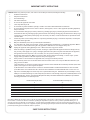
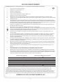
18. Exposure to extremely high noise levels may cause a permanent hearing loss. Individuals vary considerably in suscep
-
tibility to noise-induced hearing loss, but nearly everyone will lose some hearing if exposed to sufficiently intense noise
for a sufficient time. The U.S. Government’s Occupational Safety and Health Administration (OSHA) has specified the
following permissible noise level exposures:
Duration Per Day In Hours Sound Level dBA, Slow Response
8 90
6 92
4 95
3 97
2 100
1 1⁄2 102
1 105
1⁄2 110
1⁄4 or less 115
According to OSHA, any exposure in excess of the above permissible limits could result in some hearing loss. Ear plugs or protectors to
the ear canals or over the ears must be worn when operating this amplification system in order to prevent a permanent hearing loss, if
exposure is in excess of the limits as set forth above. To ensure against potentially dangerous exposure to high sound pressure levels, it is
recommended that all persons exposed to equipment capable of producing high sound pressure levels such as this amplification system be
protected by hearing protectors while this unit is in operation.
SAVE THESE INSTRUCTIONS!
Page is loading ...
Page is loading ...
Page is loading ...

7
6505
™
Tube Guitar Amplifier
Congratulations on your purchase of Peavey's 6505 guitar amplifier. 6505 Series amps feature five 12AX7 preamp tubes and
four 6L6GC power amp tubes, with presence and resonance controls and three-band EQ for taming their notorious tone. These
features, combined with its classic ultra-high gain preamp capabilities and monstrous 120 W power section result in an amp
with awesome stage presence and enough volume for any gig. For maximum flexibility, a footswitchable effects loop, preamp
output and bright/crunch voicing switches (rhythm channel) have also been included. Because of its singular design and
distinguished tone, the 6505 is in a category all its own.
FEATURES:
• 120 watts RMS into 16, 8, or 4 ohms (switchable)
• Five 12AX7 preamp tubes & four 6L6GC power amp tubes
• High & low gain inputs
• Two-channel preamp switchable on front panel or footswitch
• Rhythm channel: pre-/post-gain, bright & crunch switches
• Lead channel: pre-/post-gain
• Channels share three-band EQ
• Presence & resonance controls
• Switchable post-EQ effects loop
• Preamp output
• Footswitch included
ENGLISH

8
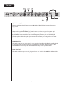
Inputs (1, 2)
The 6505 input block features HIGH [1] and NORMAL [2] GAIN inputs. The HIGH GAIN input has twice
the gain of the NORMAL gain input and should be used when maximum overdrive is desired. When both
inputs are used simultaneously, the 6505 automatically switches to the normal gain mode (6 dB pad).
Situations where both inputs are used simultaneously (alternating between two guitars on stage using
both inputs, etc.) should be avoided if peak overdrive is expected from the amp. Experimentation with
your particular guitar/pickup into each input will determine which input is best for your sound.
Channel Select Switch (3)
This allows selection of the RHYTHM or LEAD channel. Depressing the switch to the “in” position
activates the LEAD channel. The red LED light will illuminate to indicate that the LEAD channel is active.
In the “out” position the RHYTHM channel is activated and the green LED illuminates. Channels may be
remotely selected using the 6505 footswitch. If remote selection is desired, the channel select switch
must be set to the “in” position (LEAD channel).
Rhythm Pre & Post Gain (4, 11)
The RHYTHM channel PRE [4] and POST GAIN [11] operate in the same manner as the LEAD channel
gain controls. For most applications, the RHYTHM channel should be set up with the PRE GAIN at the
lower, “cleaner” settings (0-4) and the POST GAIN set for overall volume. The RHYTHM channel can be
converted to a second channel by activating the CRUNCH SWITCH [6].
Bright Switch (5)
Activates a preset boost in the treble frequencies (6 dB at 2 kHz) and affects only the rhythm channel.
Crunch Select Switch (6)
Boosts the gain of the rhythm channel to create a second “lead” channel. Depress to the “in” position
to activate.
Lead Pre & Post Gain (7, 12)
The LEAD CHANNEL PRE GAIN [7] controls the input level and works with the LEAD CHANNEL POST
GAIN [12] to determine the overall volume/overdrive of the LEAD Channel. Lower settings of the PRE
GAIN control produce a relatively clean, undistorted sound while the middle to high settings produce
harmonically rich distortion and screaming overdrive/sustain. Since both PRE and POST GAIN controls
work in “combo,” a basic rule-of-thumb setup procedure is to begin with both controls in the lower
settings (0-2). Using the PRE GAIN control, dial in the amount of overdrive/sustain you want for the
LEAD channel. Then, with the POST GAIN control adjust for overall volume.
Top Panel
1
3
5
4
2
11
6
7
12

9
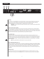
Equalization (8, 9, 10)
The 6505 equalization block features passive LOW, MID and HIGH EQ that is custom tailored to the
6505 sound.
Resonance & Presence (13, 14)
Unique to the 6505, the RESONANCE [13] control can be set to boost the gain of the power amp in
the low frequencies at the resonance/attenuation point of the speaker cabinet. In simple terms,
the RESONANCE control works like a low EQ to offset low-end frequency drop-out. The PRESENCE
[14] control works in the same manner, boosting the high frequencies. Experimentation using your
particular speaker cabinet along with personal taste will determine your setting for these important
controls.
Standby Switch (15)
This switch allows the 6505 to be placed in a non-operational standby mode. When the standby switch
is activated the tubes remain hot and ready for instantaneous operation, eliminating warm-up time.
The STANDBY LED indicator light will illuminate when the amp is in the operational mode.
Power Switch (16)
This switch supplies power to the unit. Depressed to the “on” position, the POWER LED indicator light
will illuminate indicating power is being supplied to the unit.
Top Panel
8
9
10
13
14
16
15

CAUTION
PREAMPEFFECTS
OUT
SEND
FUSE
5A
SPEAKER JACKS PARALLELE
D
120W RMS/44V RMS 4 MIN.
BUILT UNDER U.S. PATENT NO. 5,197,102
4 8 16
SPEAKER OUTPUTS
RETURN
SWITCH
60 Hz
400 WATTS
120V
GND.
0
U
S
E
F
F
U
S
E
F
U
S
E
E
S
U
F
TO REDUCE THE RISK OF FIRE OR ELECTRIC SHOCK, THIS APPARATUS
WARNING:
SHOULD NOT BE EXPOSED TO RAIN OR MOISTURE AND OBJECTS FILLED WITH LIQUIDS,
SUCH AS VASES, SHOULD NOT BE PLACED ON THIS APPARATUS. TO PREVENT THE RISK
AVIS:
ELECTRIQUE, CET APPAREIL NE DOIT PAS ETRE EXPOSE A LA PLUIE OU A L’HUMIDITE ET
AUCUN OBJET REMPLI DE LIQUIDE, TEL QU’UN VASE, NE DOIT ETRE POSE SUR CELUI-CI.
DANS LE BUT DE REDUIRE LES RISQUES D’INCENDIE OU DE DECHARGE
OF FIRE HAZARD, REPLACE WITH SAME TYPE 250 VOLT FUSE.
REMPLACER PAR UNFUSIBLE DE MEME TYPE ET DE 250 VOLTS.
REFER ALL SERVICING TO PEAVEY
AUTHORIZED SERVICE CENTER
CAUTION
ALL TUBES 12AX7A
R
A PRODUCT OF PEAVEY
ELECTRONICS CORP
.
MERIDIAN, MS MADE IN U.S.A.
10
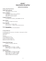
Rear Panel
Fuse (17)
A 5 amp fuse is located within the cap of the fuseholder. It must be replaced with the same type and
value in order to avoid damage to the equipment and to prevent voiding the warranty. If the amp
repeatedly blows fuses, it should be taken to a qualified service center for repair.
WARNING: The fuse should only be replaced when the power cord has been disconnected from
its power source.
Line Cord (120 V units only) (18)
For your safety, we have incorporated a three-wire line (mains) cable with proper grounding facilities.
It is not advisable to remove the ground pin under any circumstances. If it is necessary to use the 6505
without proper grounding facilities, suitable grounding adapters should be used. Greatly reduced shock
hazard exists when the unit is operated with the proper grounded receptacles.
Ground Switch (19)
This three position, rocker-type switch should be operated in the center (zero) position for most
applications. If hum or noise is noticed coming from the speaker enclosure(s) with the ground switch in
the center position, place the ground switch to positive or negative (+ or -) to minimize hum. Should a
hum/noise problem continue, consult your authorized Peavey Dealer, the Peavey factory or a qualified
service technician.
NOTE: The ground switch is not functional on 220/240 volt models.
Effects Send/Effects Return (20, 21)
Signals are supplied to outboard effects or signal processing units by patching from the EFFECTS SEND
[20] output into the outboard unit(s) and back into the EFFECTS RETURN [21] input using shielded cable
with 1/4" phono jacks. Only non-gain effects devices (chorus, reverb, delay, etc.) should be used in
the effects loop. Remote (on/off) selection of outboard effects devices can be achieved using the 6505
footswitch.
Preamp Out (22)
This output can be used to send a preamped signal from the 6505 to a mixing console, etc., using
shielded cable. Patching from the PREAMP OUT does not affect the normal operation of the amplifier.
17
18 19
20
21
22

CAUTION
PREAMPEFFECTS
OUT
SEND
FUSE
5A
SPEAKER JACKS PARALLELE
D
120W RMS/44V RMS 4 MIN.
BUILT UNDER U.S. PATENT NO. 5,197,102
4 8 16
SPEAKER OUTPUTS
RETURN
SWITCH
60 Hz
400 WATTS
120V
GND.
0
U
S
E
F
F
U
S
E
F
U
S
E
E
S
U
F
TO REDUCE THE RISK OF FIRE OR ELECTRIC SHOCK, THIS APPARATUS
WARNING:
SHOULD NOT BE EXPOSED TO RAIN OR MOISTURE AND OBJECTS FILLED WITH LIQUIDS,
SUCH AS VASES, SHOULD NOT BE PLACED ON THIS APPARATUS. TO PREVENT THE RISK
AVIS:
ELECTRIQUE, CET APPAREIL NE DOIT PAS ETRE EXPOSE A LA PLUIE OU A L’HUMIDITE ET
AUCUN OBJET REMPLI DE LIQUIDE, TEL QU’UN VASE, NE DOIT ETRE POSE SUR CELUI-CI.
DANS LE BUT DE REDUIRE LES RISQUES D’INCENDIE OU DE DECHARGE
OF FIRE HAZARD, REPLACE WITH SAME TYPE 250 VOLT FUSE.
REMPLACER PAR UNFUSIBLE DE MEME TYPE ET DE 250 VOLTS.
REFER ALL SERVICING TO PEAVEY
AUTHORIZED SERVICE CENTER
CAUTION
ALL TUBES 12AX7A
R
A PRODUCT OF PEAVEY
ELECTRONICS CORP
.
MERIDIAN, MS MADE IN U.S.A.
11
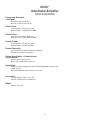
Rear Panel
Remote Footswitch Jack (23)
Provided for the connection of the supplied remote footswitch. When the footswitch is plugged into the
remote footswitch jack, the Channel Select switch [3] must be pressed to the “in” position for remote
selection to operate. Remote selection of the LEAD or RHYTHM channel (left footswitch button) or
outboard devices in the effects loop (right footswitch button) is possible with the remote footswitch.
Speaker Outputs (24)
Paralleled 1/4" output jacks for connecting speaker enclosure(s) to the amplifier (minimum: 4 ohms).
When using more than one enclosure, be sure to calculate the total impedance and set the Impedance
Switch [25] accordingly. (See section on IMPEDANCE SWITCH).
IMPORTANT: Use only high quality, UNshielded cable for speaker connections.
Impedance Selector Switch (25)
Use to select the appropriate impedance of the speaker enclosure(s). If two enclosures of equal
impedance are used, the switch should be set at one half of that value (e.g., for two 16 ohm enclosures,
set switch to 8 ohms; for two 8 ohm enclosures, set switch to 4 ohms).
When connecting the amplifier to the speaker enclosure, make sure to set the impedance selector
switch on the rear of the unit to the impedance that matches your enclosure. When two enclosures
of equal impedance are used, set the switch to one half the impedance of one enclosure (see [25]
Impedance Selector Switch). The 6505 is designed to operate into a minimum of 4 ohms.
23
24
25
Speaker Connection

12
6505
™
Tube Guitar Amplifier
SPECIFICATIONS
Power Amplifier Section:
Rated Power and Load:
120 W RMS into 16, 8, or 4 ohms
Power @ Clipping:
(Typically @ 5% THD, 1 kHz, 120 V AC line)
130 W RMS into 16, 8, or 4 ohms
(Bias must be reduced to measure)
Frequency Response:
+0, -3 dB, 50 Hz to 20 kHz, @ 100 W RMS into 8 ohms
Hum & Noise:
Greater than 75 dB below rated power
Power Amp EQ:
Active Presence: +10 dB @ 2 kHz
Active Resonance: + 10 dB @ cabinet resonant frequency
Power Consumption:
400 watts 50/60 Hz, 120 V AC (Domestic)
Preamp Section:
The following specs are measured @ 1 kHz with the controls preset as follows:
Low & High EQ @ 10
Mid EQ @ 0
Bright out
Lead & Rhythm Posts @ 10
Presence & Resonance @ 0 dB
Nominal levels with Pre Gains @ 5
Minimum levels with Pre Gains @ 10
Preamp High Gain Input:
Impedance: Very High-Z, 470K ohms
Lead Channel:
(with channel select in)
Nominal Input Level: -80 dBV, .1 mV RMS
Minimum Input Level: -92 dBV, .025 mV RMS
Clean Channel:
(with channel select out)
Nominal Input Level: -34 dBV, 20 mV RMS
Minimum Input Level: -50 dBV, 3 mV RMS
Maximum Input Level: 0 dBV, 1.0 V RMS
(Subtract 16 dB with Crunch switch in)

13
6505
™
Tube Guitar Amplifier
SPECIFICATIONS
Preamp Low Gain Input:
(-6 dB pad):
Impedance: High-Z, 44K ohms
All levels are increased by +6 dB
Effects Send:
Load Impedance: 47K ohms or greater
Nominal Output: -10 dBV, 300 mV RMS
Effects Return:
Impedance: Very High-Z, 470K ohms
Designed Level: -10 dBV, 300 mV RMS
Preamp Output:
Load Impedance: 47K ohms or greater
Nominal Output: +10 dBV, 3 V RMS
Remote Footswitch:
Special 2 button unit with LED indicators (supplied)
Channel select & Effects loop bypass
System Hum & Noise @ Nominal Level:
(Clean channel):
(20 Hz to 20 kHz unweighted)
Greater than 74 dB below rated power
Equalization:
Custom Low, Mid & High passive type EQ Push Bright (Rhythm channel only)
+6 dB @ 2 kHz
Push Crunch (Rhythm channel only) Increases gain
Dimensions:
10" (H) x 26.625" (W) x 11.75" (D)
254 mm x 676.275 mm x 756.92 mm
Weight:
48.3 lbs. (21.9 kg)
Page is loading ...

15
PEAVEY ELECTRONICS CORPORATION LIMITED WARRANTY
Effective Date: July 1, 1998
What This Warranty Covers
Your Peavey Warranty covers defects in material and workmanship in Peavey products purchased and serviced in the U.S.A. and Canada.
What This Warranty Does Not Cover
The Warranty does not cover: (1) damage caused by accident, misuse, abuse, improper installation or operation, rental, product modification or neglect; (2) dam
-
age occurring during shipment; (3) damage caused by repair or service performed by persons not authorized by Peavey; (4) products on which the serial number
has been altered, defaced or removed; (5) products not purchased from an Authorized Peavey Dealer.
Who This Warranty Protects
This Warranty protects only the original retail purchaser of the product.
How Long This Warranty Lasts
The Warranty begins on the date of purchase by the original retail purchaser. The duration of the Warranty is as follows:
Product Category Duration
Guitars/Basses, Amplifiers, Pre-Amplifiers, Mixers, Electronic
Crossovers and Equalizers 2 years *(+ 3 years)
Drums 2 years *(+ 1 year)
Enclosures 3 years *(+ 2 years)
Digital Effect Devices and Keyboard and MIDI Controllers 1 year *(+ 1 year)
Microphones 2 years
Speaker Components (incl. speakers, baskets, drivers,
diaphragm replacement kits and passive crossovers)
and all Accessories 1 year
Tubes and Meters 90 days
[*Denotes additional warranty period applicable if optional Warranty Registration Card is completed and returned to Peavey by original retail purchaser within 90 days of pur-
chase.]
What Peavey Will Do
We will repair or replace (at Peavey's discretion) products covered by warranty at no charge for labor or materials. If the product or component must be shipped to
Peavey for warranty service, the consumer must pay initial shipping charges. If the repairs are covered by warranty, Peavey will pay the return shipping charges.
How To Get Warranty Service
(1) Take the defective item and your sales receipt or other proof of date of purchase to your Authorized Peavey Dealer or Authorized Peavey Service Center.
OR
(2) Ship the defective item, prepaid, to Peavey Electronics Corporation, International Service Center, 412 Highway 11 & 80 East, Meridian, MS 39301 or Peavey
Canada Ltd., 95 Shields Court, Markham, Ontario, Canada L3R 9T5. Include a detailed description of the problem, together with a copy of your sales receipt or
other proof of date of purchase as evidence of warranty coverage. Also provide a complete return address.
Limitation of Implied Warranties
ANY IMPLIED WARRANTIES, INCLUDING WARRANTIES OF MERCHANTABILITY AND FITNESS FOR A PARTICULAR PURPOSE, ARE LIMITED IN DURATION TO THE
LENGTH OF THIS WARRANTY.
Some states do not allow limitations on how long an implied warranty lasts, so the above limitation may not apply to you.
Exclusions of Damages
PEAVEY'S LIABILITY FOR ANY DEFECTIVE PRODUCT IS LIMITED TO THE REPAIR OR REPLACEMENT OF THE PRODUCT, AT PEAVEY'S OPTION. IF WE ELECT TO
REPLACE THE PRODUCT, THE REPLACEMENT MAY BE A RECONDITIONED UNIT. PEAVEY SHALL NOT BE LIABLE FOR DAMAGES BASED ON INCONVENIENCE, LOSS OF
USE, LOST PROFITS, LOST SAVINGS, DAMAGE TO ANY OTHER EQUIPMENT OR OTHER ITEMS AT THE SITE OF USE, OR ANY OTHER DAMAGES WHETHER INCIDENTAL,
CONSEQUENTIAL OR OTHERWISE, EVEN IF PEAVEY HAS BEEN ADVISED OF THE POSSIBILITY OF SUCH DAMAGES.
Some states do not allow the exclusion or limitation of incidental or consequential damages, so the above limitation or exclusion may not apply to you.
This Warranty gives you specific legal rights, and you may also have other rights which vary from state to state.
If you have any questions about this warranty or service received or if you need assistance in locating an Authorized Service Center, please contact the Peavey
International Service Center at (601) 483-5365 / Peavey Canada Ltd. at (905) 475-2578.
Features and specifications subject to change without notice.

Features and specifications subject to change without notice.
Peavey Electronics Corporation • 711 A Street • Meridian, MS 39301
(601) 483-5365 • FAX (601) 486-1278 • www.peavey.com
80303147
© 2005
-
 1
1
-
 2
2
-
 3
3
-
 4
4
-
 5
5
-
 6
6
-
 7
7
-
 8
8
-
 9
9
-
 10
10
-
 11
11
-
 12
12
-
 13
13
-
 14
14
-
 15
15
-
 16
16


Peavey 6505 User manual
- Category
- Musical Instrument Amplifier
- Type
- User manual
Ask a question and I''ll find the answer in the document
Finding information in a document is now easier with AI
in other languages
- français: Peavey 6505 Manuel utilisateur
Related papers
-
Peavey 6505 PLUS User manual
-
-
-
 Peavy PV Series Power Amplifer Owner's manual
-
Peavey Classic 30 User manual
-
-
Peavey CS 4000 Owner's manual
-
 Peavy Classic 50 410 User manual
-
-


Other documents
-
 Architectural Acoustics IP-Six User manual
-
Crest Audio CPX 3800 User manual
-
-
-
 HH Electronics HPT-112 User manual
-
HH Electronics HPT-110 User manual
-
 Harley Benton TE-20 SB Standard Serie Set 1 Owner's manual
-
Harley Benton HB-10G User manual
-
thomann Guitar Set G2 Sunburst Owner's manual
-


