
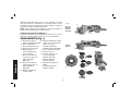
D28114, D28114N, D28131, D28140, D28144, D28144N
Heavy-Duty Small Angle Grinders
Petites meuleuses à renvoi d’angle de type industriel
Esmeriladoras de ángulo pequeño para trabajo pesado
INSTRUCTION MANUAL
GUIDE D’UTILISATION
MANUAL DE INSTRUCCIONES
INSTRUCTIVO DE OPERACIÓN, CENTROS DE SERVICIO Y PÓLIZA
DE GARANTÍA. ADVERTENCIA: LÉASE ESTE INSTRUCTIVO
ANTES DE USAR EL PRODUCTO.
If you have questions or comments, contact us.
Pour toute question ou tout commentaire, nous contacter.
Si tiene dudas o comentarios, contáctenos.
1-800-4-DEWALT • www.dewalt.com

English
1
IF YOU HAVE ANY QUESTIONS OR COMMENTS ABOUT THIS
OR ANY D
EWALT TOOL, CALL US TOLL FREE AT:
1-800-4-D
EWALT (1-800-433-9258)
General Safety Rules – For All Tools
WARNING! Read and understand all instructions.
Failure to follow all instructions listed below may result
in electric shock, fire and/or serious personal injury.
SAVE THESE INSTRUCTIONS
WORK AREA
• Keep your work area clean and well lit. Cluttered benches
and dark areas invite accidents.
• Do not operate power tools in explosive atmospheres, such
as in the presence of flammable liquids, gases, or dust.
Power tools create sparks which may ignite the dust or fumes.
• Keep bystanders, children, and visitors away while operat-
ing a power tool. Distractions can cause you to lose control.
ELECTRICAL SAFETY
• Grounded tools must be plugged into an outlet properly
installed and grounded in accordance with all codes and
ordinances. Never remove the grounding prong or modify
the plug in any way. Do not use any adaptor plugs. Check
with a qualified electrician if you are in doubt as to whether
the outlet is properly grounded. If the tools should electrically
malfunction or break down, grounding provides a low resistance
path to carry electricity away from the user. Applicable only to
Class I (grounded) tools.
• Double insulated tools are equipped with a polarized plug
(one blade is wider than the other.) This plug will fit in a
polarized outlet only one way. If the plug does not fit fully in
the outlet, reverse the plug. If it still does not fit, contact a
qualified electrician to install a polarized outlet. Do not
change the plug in any way. Double insulation
eliminates
the need for the three wire grounded power cord and grounded
power supply system. Applicable only to Class II (double
insulated) tools.
• Avoid body contact with grounded surfaces such as pipes,
radiators, ranges and refrigerators. There is an increased risk
of electric shock if your body is grounded.
• Don’t expose power tools to rain or wet conditions. Water
entering a power tool will increase the risk of electric shock.
• Do not abuse the cord. Never use the cord to carry the
tools or pull the plug from an outlet. Keep cord away from
heat, oil, sharp edges or moving parts. Replace damaged
cords immediately. Damaged cords increase the risk of electric
shock.
• When operating a power tool outside, use an outdoor exten-
sion cord marked “W-A” or “W.” These cords are rated for
outdoor use and reduce the risk of electric shock. When using
an extension cord, be sure to use one heavy enough to carry the
current your product will draw. An undersized cord will cause a
drop in line voltage resulting in loss of power and overheating.
The following table shows the correct size to use depending on
cord length and nameplate ampere rating. If in doubt, use the
next heavier gauge. The smaller the gauge number, the heavier
the cord.
Minimum Gauge for Cord Sets
Volts Total Length of Cord in Feet
120V 0-25 26-50 51-100 101-150
240V 0-50 51-100 101-200 201-300
Ampere Rating
More Not more AWG
Than Than
0 - 6 18 16 16 14
6 - 10 18 16 14 12
10 - 12 16 16 14 12
12 - 16 14 12 Not Recommended

English
2
PERSONAL SAFETY
• Stay alert, watch what you are doing and use common
sense when operating a power tool. Do not use tool while
tired or under the influence of drugs, alcohol, or medica-
tion. A moment of inattention while operating power tools may
result in serious personal injury.
• Dress properly. Do not wear loose clothing or jewelry.
Contain long hair. Keep your hair, clothing, and gloves away
from moving parts. Loose clothing, jewelry, or long hair can be
caught in moving parts. Air vents often cover moving parts and
should also be avoided.
• Avoid accidental starting. Be sure switch is off before plug-
ging in. Carrying tools with your finger on the switch or plugging
in tools that have the switch on invites accidents.
• Remove adjusting keys or wrenches before turning the tool
on. A wrench or a key that is left attached to a rotating part of
the tool may result in personal injury.
• Do not overreach. Keep proper footing and balance at all
times. Proper footing and balance enables better control of the
tool in unexpected situations.
• Use safety equipment. Always wear eye protection. Dust
mask, non-skid safety shoes, hard hat, or hearing protection
must be used for appropriate conditions.
TOOL USE AND CARE
• Use clamps or other practical way to secure and support
the workpiece to a stable platform. Holding the work by
hand or against your body is unstable and may lead to loss of
control.
• Do not force tool. Use the correct tool for your application.
The correct tool will do the job better and safer at the rate for
which it is designed.
• Do not use tool if switch does not turn it on or off. Any tool
that cannot be controlled with the switch is dangerous and must
be repaired.
• Disconnect the plug from the power source before making
any adjustments, changing accessories, or storing the tool.
Such preventative safety measures reduce the risk of starting
the tool accidentally.
• Store idle tools out of reach of children and other untrained
persons. Tools are dangerous in the hands of untrained users.
• Maintain tools with care. Keep cutting tools sharp and
clean. Properly maintained tools, with sharp cutting edges are
less likely to bind and are easier to control.
• Check for misalignment or binding of moving parts, break-
age of parts, and any other condition that may affect the
tool’s operation. If damaged, have the tool serviced before
using. Many accidents are caused by poorly maintained tools.
• Use only accessories that are recommended by the manu-
facturer for your model. Accessories that may be suitable for
one tool, may become hazardous when used on another tool.
SERVICE
• Tool service must be performed only by qualified repair
personnel. Service or maintenance performed by unqualified
personnel could result in a risk of injury.
• When servicing a tool, use only identical replacement parts.
Follow instructions in the Maintenance section of this man-
ual. Use of unauthorized parts or failure to follow maintenance
instructions may create a risk of electric shock or injury.
Additional Specific Safety Instructions
for Grinders
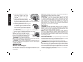
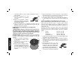
• Check that the grinding wheel backing flange has a yellow
rubber ring (D) installed, see Figure 1. Replace rubber ring if
missing, damaged or worn. See page 10 for details regarding
proper accessory installation.
WARNING: The grinding wheel or accessory may loosen dur-
ing coast-down of the tool when shut off if rubber ring is miss-
ing or damaged. If grinding wheel or accessory loosens, it may
dismount from the machine and may cause serious personal injury.

English
3
• Always use proper guard with grinding wheel. A guard pro-
tects operator from broken wheel fragments and wheel contact.
• Accessories must be rated for at least the speed recom-
mended on the tool warning label. Wheels and other acces-
sories running over rated speed can fly apart and cause injury.
Accessory ratings must be above listed minimum wheel speed
as shown on tool nameplate.
• Hold tool by insulated gripping surfaces when performing
an operation where the cutting tool may contact hidden
wiring or its own cord. Contact with a “live” wire will make
exposed metal parts of the tool “live” and shock the operator.
• Do not use Type 11 (flaring cup) wheels on this tool. Using
inappropriate accessories can result in injury.
• ALWAYS WEAR EYE PROTECTION WHEN USING THIS
TOOL.
• Use of accessories not specified in this manual is not rec-
ommended and may be hazardous. Use of power boosters
that would cause the tool to be driven at speeds greater than its
rated speed constitutes misuse.
• Do not use circular saw blades or any other toothed blades
with this tool. Serious injury may result.
• When starting the tool with a new or replacement wheel,
or a new or replacement wire brush installed, hold the tool
in a well protected area and let it run for one minute. If the
wheel has an undetected crack or flaw, it should burst in less
than one minute. If the wire brush has loose wires, they will
be detected. Never start the tool with a person in line with the
wheel. This includes the operator.
• Avoid bouncing the wheel or giving it rough treatment. If this
occurs, stop the tool and inspect the wheel for cracks or flaws.
• Direct sparks away from operator, bystanders or flammable
materials. Sparks may be produced while cutting and/or
grinding. Sparks may cause burns or start fires.
• Always use side handle. Tighten the handle securely. The
side handle should always be used to maintain control of the tool
at all times.
• Never cut into area that may contain electrical wiring or
piping. Serious injury may result.
• Clean out your tool often, especially after heavy use. Dust
and grit containing metal particles often accumulate on interior
surfaces and could create an electric shock hazard.
• Do not operate this tool for long periods of time. Vibration
caused by the operating action of this tool may cause permanent
injury to fingers, hands, and arms. Use gloves to provide extra
cushion, take frequent rest periods, and limit daily time of use.
• Direct the Dust Ejection System (DES) away from operator
and coworkers. Serious injury may result (Fig. 1, K).
• The label on your tool may include the following symbols. The
symbols and their definitions are as follows:
V ..........volts A .............amperes
Hz ........hertz W ............watts
min ......minutes
...........alternating current
....direct current
n
o ............no load speed
.......Class II Construction ...........safety alert symbol
........earthing terminal …/min .....revolutions per minute
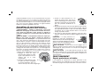
Causes and Operator Prevention
of Kickback
• Kickback is a sudden reaction to a pinched, bound or misaligned
wheel, wire brush or flap disc causing an uncontrolled cut-off tool
to lift up and out of the workpiece toward the operator.
• When the wheel is pinched or bound tightly by the workpiece,
the wheel stalls and the motor reaction drives the unit rapidly
back toward or away from the operator.
• Kickback is the result of tool misuse and/or incorrect operating
procedures or conditions and can be avoided by taking proper
precautions as given below:
• Maintain a firm grip with both hands on the unit and posi-
tion your body and arm to allow you to resist kickback

English
4
forces. Kickback forces can be controlled by the operator, if
proper precautions are taken.
• When wheel is binding, or when interrupting a cut for any
reason, release the trigger and hold the unit motionless
in the material until the wheel comes to a complete stop.
Never attempt to remove the unit from the work or pull the
unit backward while the wheel is in motion or kickback
may occur. Investigate and take corrective actions to elimi-
nate the cause of wheel binding.
• When restarting a cut-off tool in the workpiece, check
that the wheel is not engaged into the material. If wheel is
binding, it may walk up or kickback from the workpiece as the
tool is restarted.
• Support large panels to minimize the risk of wheel pinch-
ing and kickback. Large panels tend to sag under their own
weight. Support must be placed under the panel on both
sides, near the line of cut and near the edge of the panel.
WARNING: Some dust created by power sanding, sawing,
grinding, drilling, and other construction activities contains chem-
icals known to cause cancer, birth defects, or other reproductive
harm. Some examples of these chemicals are:
• lead from lead-based paints,
• crystalline silica from bricks and cement and other masonry
products, and
• arsenic and chromium from chemically-treated lumber (CCA).
Your risk from these exposures varies, depending on how often you
do this type of work. To reduce your exposure to these chemicals:
work in a well ventilated area, and work with approved safety equip-
ment, such as those dust masks that are specially designed to filter
out microscopic particles.
• Avoid prolonged contact with dust from power sanding,
sawing, grinding, drilling, and other construction activities.
Wear protective clothing and wash exposed areas with soap
and water. Allowing dust to get into your mouth, eyes, or lay on
the skin may promote absorption of harmful chemicals.
WARNING: Use of this tool can generate and/or disburse dust,
which may cause serious and permanent respiratory or other injury.
Always use NIOSH/OSHA approved respiratory protection appropri-
ate for the dust exposure. Direct particles away from face and
body.
CAUTION: Use extra care when working into a corner because
a sudden, sharp movement of the grinder may be experienced
when the wheel or other accessory contacts a secondary surface
or a surface edge.
CAUTION: Wear appropriate personal hearing protection
during use. Under some conditions and duration of use, noise
from this product may contribute to hearing loss.
FEATURES
E-SWITCH PROTECTION™
The ON/OFF switch has a no-volt release function. In the event of
a power outage or other unexpected shut down, the switch needs
to be cycled (turned off and on) to restart tool.
CLUTCH (D28140, D28144, D28144N)
The torque limiting clutch reduces the maximum reaction torque
transmitted to the operator in case of jamming a cutting disc. This
feature also prevents the gearing and electric motor from stalling.
The torque limiting clutch has been factory set and cannot be
adjusted.
E-CLUTCH™
This unit is equipped with an E-Clutch™ (Electronic Clutch), which
in the event of a high-load or wheel pinch, the unit will shut off to
reduce the reaction torque to the user. The switch needs to be
cycled (turned off and on) to restart the tool.
POWER-OFF™ OVERLOAD PROTECTION
The power supply to the motor will be reduced in case of motor
overload. With continued motor overload, the tool will shut off. The

English
5
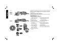
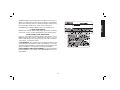
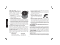
G1
A
B
C
F
I
J
FIG. 1
D28114
D28114N
D28144
D28144N
D28131
D28140
L
K
K
switch must be cycled (turned off and on) to restart tool. The power
will return to normal once the tool has cooled down to a suitable
operating temperature. NOTE: Run the tool at no load to reduce the
cool down time.
COMPLETE ELECTRONIC CONTROL™
The internal electronic speed control offers consistent wheel speed
while using the tool.
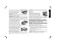
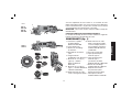
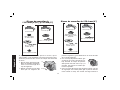
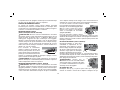
COMPONENTS (Fig. 1)
A. Paddle Switch: D28114, G2. Stamped Steel Quick-Change
D28144, D28144N Backing Flange (depressed
B. Lock-Off Lever center wheels only):
C. Spindle Lock Button D28140, D28144, D28144N
D. Yellow Rubber Ring H. Threaded Clamp Nut
E. Anti-Vibration Side Handle I1. Type 27 Guard
(not shown) I2. Type 1 Guard (not shown):
F. 5" Grinding Wheel D28140, D28144, D28144N
(Type 27): D28114, J. Lock On Button:
D28131, D28114N D28114, D28144
F1. 6" Grinding Wheel K. Dust Ejection System™ (DES)
(Type 1): D28140, L. Slider Switch: D28131, D28140
D28144, D28144N
G1. Quick-Change Backing
Flange
K
D
H
G2

English
6
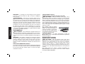
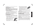
ASSEMBLY AND ADJUSTMENTS
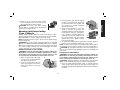
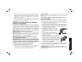
ATTACHING SIDE HANDLE
E
The side handle (E) can be fitted to either side of
the gear case in the threaded holes, as shown.
Before using the tool, check that the handle
is tightened se cure ly. Use a wrench to firmly
tighten the side handle.
Rotating the Gear Case
WARNING: Turn off and unplug tool before making any
adjustments or removing or installing accessories. Before
reconnecting the tool, depress and release the trigger switch
to ensure that the tool is off.
1. Remove guard and flanges from tool.
2. Remove the four corner screws attaching the gear case to
motor housing.
3. Separating the gear case from motor housing not more than
1/4", rotate the gear case head to desired position.
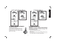
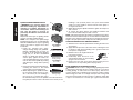
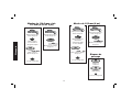
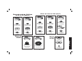
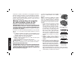
Type 27 guard
4-1/2" and 5" Grinding Wheels
Quick-change
backing flange
threaded clamp nut
Type 27 hubbed wheel
Type 27 guard
Type 27 depressed
center wheel
6" Grinding Wheels
Type 27 guard
stamped steel
Quick-Change
backing flange
threaded clamp nut
Type 27 hubbed wheel
Type 27 guard
Type 27 depressed
center wheel

English
7
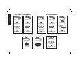
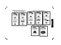
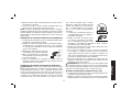
4-1/2" and 5" Cutting Wheels
Type 1 guard
Quick-Change
backing flange
Type 1 abrasive
cutting wheel
threaded clamp nut
Type 1 guard
Quick-Change
backing flange
diamond cutting wheel
threaded clamp nut
6" Cutting Wheels
rubber backing pad
sanding disc
threaded clamp nut
Sanding Discs
Wire Wheels
3" wire cup
brush
4" wire wheel
Type 27 guard
Type 27 guard
Type 1 guard
Quick-Change
backing flange
Type 1 abrasive
cutting wheel
threaded clamp nut
Type 1 guard
Quick-Change
backing flange
diamond cutting wheel
threaded clamp nut
Type 27 guard
Type 27 depressed
center wheel
threaded clamp nut
stamped steel
Quick-Change
backing flange

English
8
NOTE: If the gear case and motor housing become separated
by more than 1/4", the tool must be serviced and re-assembled
by a D
EWALT service center. Failure to have the tool serviced
may cause brush, motor and bearing failure.
4. Re-install screws to attach the gear case to the motor hous-
ing. Tighten screws to 18 in./lbs. torque. Overtightening could
cause screws to strip.
5. Re-install guard and correct flanges for the appropriate acces-
sories.
Accessories
It is important to choose the correct guards, backing pads and
flanges to use with grinder accessories. See pages 6–8 for infor-
mation on choosing the correct accessories.
WARNING: Accessories must be rated for at least the speed
recom mended on the tool warning label. Wheels and other acces-
sories running over rated accessory speed may burst and cause
injury. Threaded accessories must have a 5/8"-11 hub. Every
unthreaded accessory must have a 7/8" arbor hole. If it does not,
it may have been designed for a circular saw and should not be
used. Use only the accessories shown on pages 6–8 of this man-
ual. Accessory ratings must be above listed minimum wheel speed
as shown on tool nameplate.
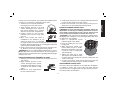
Mounting Guard
MOUNTING AND REMOVING GUARD
WARNING: Turn off and unplug the tool before making any
adjustments or removing or installing attachments or acces-
sories. Before reconnecting the tool, depress and release the
paddle switch to ensure that the tool is off.
CAUTION: Guards must be used with all grinding wheels, sand-
ing flap discs, wire brushes, and wire wheels. The tool may be used
without a guard only when sanding with conventional sanding discs.
Some DeWALT models are provided with a guard intended for use
with depressed center wheels (Type 27) and hubbed grinding
wheels (Type 27). The same guard is designed for use with sanding
flap discs (Type 27 and 29) and wire brushes. Grinding and cutting
with wheels other than Type 27 and 29 require different accessory
guards not included with tool. Mounting instructions for these
accessory guards are included in the accessory package.
1. Open the guard latch (M). Align the lugs (N) on the guard with
the slots (O) on the gear case.
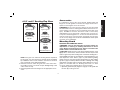
4-1/2" and 5" Sanding Flap Discs
hubbed sanding
flap disc
Quick-Change
backing flange
non-hubbed sanding
flap disc
threaded clamp nut
Type 27 guard
Type 27 guard

English
9
2. Push the guard down until the
M
O
N
guard lugs engage and rotate
freely in the groove on the gear
case hub.
3. With the guard latch open, rotate the
guard (I) into the desired working
position. The guard body should
be positioned between the spindle and the operator to provide
maximum operator protection.
4. Close the guard latch to secure the guard
I
on the gear case. You should not be able
to rotate the guard by hand when the
latch is closed. Do not operate the grind-
er with a loose guard or the clamp lever
in open position.
5. To remove the guard, open the guard latch, rotate the guard so
that the arrows are aligned and pull up on the guard.
NOTE: The guard is pre-adjusted to the
P
diameter of the gear case hub at the fac-
tory. If, after a period of time, the guard
becomes loose, tighten the adjusting screw
(P) with clamp lever in the closed position.
CAUTION: Do not tighten the adjusting
screw with the clamp lever in open position. Undetectable damage
to the guard or the mounting hub may result.
CAUTION: If guard cannot be tightened by adjusting clamp, do
not use tool and take the tool and guard to a service center to repair
or replace the guard.
OPERATION
Guards and Flanges
It is important to choose the correct guards and flanges to use
with the grinder accessories. See pages 6–8 for the correct
accessories.
NOTE: Edge grinding and cutting can be performed with Type 27
wheels designed and specified for this purpose.
WARNING: Accessories must be rated for at least the speed
recom mended on the tool warning label. Wheels and other
accessories running over rated accessory speed may burst and
cause injury. Every unthreaded accessory must have a 7/8” arbor
hole. If it does not, it may have been designed for a circular saw
and should not be used. Use only the accessories shown on
pages 6–8. Accessory ratings must be above listed minimum
wheel speed as shown on tool nameplate.
Switches
CAUTION: Hold the side handle and body of the tool firmly to
maintain control of the tool at start up and during use and until the
wheel or accessory stops rotating. Make sure the wheel has come
to a complete stop be fore laying the tool down.
NOTE: To reduce unexpected tool movement, do not switch the
tool on or off while under load conditions. Allow the grinder to run
up to full speed before touching the work surface. Lift the tool from
the surface before turning the tool off. Allow the tool to stop rotating
before putting it down.
SOFT START FEATURE
The soft start feature allows a slow speed build-up to avoid an initial
jerk when starting. This feature is particularly useful when working
in confined areas. Current surge will also be reduced.
PADDLE SWITCH (D28114, D28114N, D28144, D28144N)
CAUTION: Before connecting the tool to a power source depress
and release the paddle switch (A) once without depressing the
lock-on button (Fig. 1, J) [D28114, D28144 only] to ensure that the
switch is off. Depress and release the paddle switch as described
above after any interruption in power supply to the tool, such as the
activation of a ground fault interrupter, throwing of a circuit breaker,
accidental unplugging, or power failure.

English
10
To turn the tool on, push the
A
B
lock-off lever (B) toward the back of
the tool, then depress the paddle
switch (A). The tool will run while the
switch is depressed. Turn the tool off
by releasing the paddle switch.
WARNING: Do not disable the lock-off lever. If the lock-off lever
is disabled, the tool may start unexpectedly when it is laid down.
SLIDER SWITCH (D28131, D28140)
CAUTION: Before connecting the tool to a power supply, be sure
the switch is in the off position by pressing the rear part of the switch
and releasing. Ensure the switch is in the off position as described
above after any interruption in power supply to the tool, such as the
activation of a ground fault interrupter, throwing of a circuit breaker,
accidental unplugging, or power failure.
To start the tool, slide the ON/OFF switch
L
(L) toward the front of the tool. To stop
the tool, release the ON/OFF switch.
For continuous operation, slide the
switch toward the front of the tool and
press the forward part of the switch
inward. To stop the tool while operating in continuous mode,
press the rear part of the switch and release.
LOCK-ON BUTTON (D28114, D28144)
The lock-on button (J) offers increased
J
A
B
comfort in extended use applications.
To lock the tool on, push the lock-off
lever (B) toward the back of the tool
then depress the paddle switch (A).
With the tool running, depress the
lock-on button (J). The tool will contin-
ue to run after the paddle switch is released. To unlock the tool,
depress and release the paddle switch. This will cause the tool to
stop.
CAUTION: Allow the tool to reach full speed before touching tool
to the work surface. Lift the tool from the work surface before turn-
ing the tool off.
SPINDLE LOCK
C
The spindle lock (C) is provided to prevent
the spindle from rotating when installing or
removing wheels. Operate the spindle lock
only when the tool is turned off, unplugged
from the power supply, and has come to
a complete stop. Do not engage the spindle lock while the tool is
operating because damage to the tool will result. To engage the
lock, depress the spindle lock button and rotate the spindle until
you are unable to rotate the spindle further.
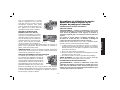
Mounting and Using Depressed Center
Grinding Wheels and Sanding Flap Discs
MOUNTING AND REMOVING HUBBED WHEELS
WARNING: Turn off and unplug the tool before making any
adjustments or removing or installing attachments or acces-
sories. Before reconnecting the tool, depress and release the
paddle switch to ensure that the tool is off.
Hubbed wheels install directly on the 5/8"-11 threaded spindle.
Thread of accessory must match thread of spindle.
1. Backing flange is retained to the grinder by an O-ring on the
spindle. Remove backing flange by pulling and twisting flange
away form the machine.
2. Thread the wheel on the spindle by hand.
3. Depress the spindle lock button and use a wrench to tighten
the hub of the wheel.
4. Reverse the above procedure to remove the wheel.
CAUTION: Failure to properly seat the wheel before turning the
tool on may result in damage to the tool or the wheel.

English
11
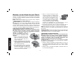
MOUNTING NON-HUBBED WHEELS
G1
D
WARNING: Turn off and unplug the
tool before making any adjustments or
removing or installing attachments or
accessories. Before reconnecting the
tool, turn the switch on and off as
previously described to ensure that the
tool is off.
Depressed center Type 27 grinding wheels
H
must be used with included flanges.
NOTE: The stamped steel quick-change
backing flange (G2) is for use with D28140,
D28144 and D28144N for Type 27 grinding
wheels only. Refer to page 6–8 for more
1/4" WHEELS
(6.35 mm)
Quick-Change
backing flange
threaded clamp nut
1/8" WHEELS
(3.17 mm)
threaded clamp nut
Quick-Change
backing flange
information.
1. Install the stamped steel quick-
change backing flange (G2) (D28140,
D28144, D28144N only) for Type 27
6” wheels or the quick-change backing
flange (G1) for all other non-hubbed
wheels on spindle (D) with the raised
section (pilot) against the wheel. Be
sure the backing flange recess is seated
onto the flats of the spindle by pushing
and twisting the flange before placing
wheel.
2. Place wheel against the backing flange,
centering the wheel on the raised
section (pilot) of the backing flange.
3. While depressing the spindle lock but-
ton, thread the clamp nut (H) on spin-
dle. If the wheel you are installing is
more than 1/8" (3.31mm) thick, place
the threaded clamp nut on the spindle so that the raised sec-
tion (pilot) fits into the center of the wheel. If the wheel you are
installing is 1/8" (3.31mm) thick or less, place the threaded
clamp nut on the spindle so that the raised section (pilot) is
not against the wheel.
4. While depressing the spindle lock button, tighten the clamp nut
with a wrench.
5. To remove the wheel, depress the spindle lock button and
loosen the threaded clamp nut with a wrench.
NOTE: If the wheel spins after the clamp nut is tightened, check the
orientation of the threaded clamp nut. If a thin wheel is installed with
the pilot on the clamp nut against the wheel, it will spin because the
height of the pilot prevents the clamp nut from holding the wheel.
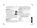
SURFACE GRINDING WITH GRINDING WHEELS
1. Allow the tool to reach full speed before touching the tool to the
work surface.
2. Apply minimum pressure to the work surface, allowing the tool
to operate at high speed. Grinding rate is greatest when the
tool operates at high speed.
3. Maintain a 20˚ to 30˚ angle between the
20˚-30˚
tool and work surface.
4. Continuously move the tool in a for-
ward and back motion to avoid creating
gouges in the work surface.
5. Remove the tool from work surface before turning tool off.
Allow the tool to stop rotating before laying it down.
EDGE GRINDING WITH GRINDING WHEELS
CAUTION: Wheels used for cutting and edge grinding may break
if they bend or twist while the tool is being used to do cut-off work
or deep grinding. To reduce the risk of serious injury, limit the use
of these wheels with a standard Type 27 guard to shallow cutting
and notching (less than 1/2" in depth). The open side of the guard
must be positioned away from the operator. For deeper cutting with
a Type 1 cut-off wheel, use a closed, Type 1 guard. See the chart

English
12
on page 7 for more information. Type 1 guards are available at extra
cost from your local dealer or authorized service center.
1. Allow the tool to reach full speed before
touching the tool to the work surface.
2. Apply minimum pressure to the work
surface, allowing the tool to operate at
high speed. Grinding rate is greatest
when the tool operates at high speed.
3. Position yourself so that the open-
underside of the wheel is facing away
from you.
4. Once a cut is begun and a notch is
established in the workpiece, do not
change the angle of the cut. Changing
the angle will cause the wheel to bend and may cause wheel
breakage. Edge grinding wheels are not designed to withstand
side pressures caused by bending.
5. Remove the tool from the work surface before turning the tool
off. Allow the tool to stop rotating before laying it down.
WARNING: Do not use edge grinding/cutting wheels for surface
grinding applications because these wheels are not designed for
side pressures encountered with surface grinding. Wheel breakage
and injury may result.
SURFACE FINISHING WITH SANDING FLAP DISCS
1. Allow the tool to reach full speed before touching the tool to the
work surface.
2. Apply minimum pressure to work
5˚-10˚
surface, allowing the tool to operate
at high speed. Sanding rate is great-
est when the tool operates at high
speed.
3. Maintain a 5˚ to 10˚ angle between
the tool and work surface.
4. Continuously move the tool in a forward and backward motion
to avoid creating gouges in the work surface.
5. Remove the tool from work surface before turning tool off.
Allow the tool to stop rotating before laying it down.
MOUNTING SANDING BACKING PADS
WARNING: Turn off and unplug the tool before making any
adjustments or removing or installing attachments or acces-
sories. Before reconnecting the tool, turn the switch on and
off as previously described to ensure that the tool is off.
CAUTION: Proper guard must be reinstalled for grinding wheel,
sanding flap disc, wire brush or wire wheel applications after sand-
ing applications are complete.
1. Place or appropriately thread
H
R
S
pad backing (R) on the spindle.
2. Place the sanding disc (S) on the
backing pad.
3. While depressing spindle lock,
thread clamp nut (H) on spindle,
piloting the raised hub on the clamp
nut into the center of san ding disc
and backing pad.
4. Tighten the clamp nut by hand.
Then depress the spindle lock but-
ton while turning the sanding disc until the sanding disc and
clamp nut are snug.
5. To remove the wheel, grasp and turn the backing pad and
sanding pad while depressing the spindle lock button.
USING SANDING BACKING PADS
Choose the proper grit sandpaper for your application. Sandpaper
is available in various grits. Coarse grits yield faster material
removal rates and a rougher finish. Finer grits yield slower mate-
rial removal and a smoother finish.

English
13
Begin with coarse grit discs for fast, rough material removal.
Move to a medium grit paper and finish with a fine grit disc for
optimal finish.
Coarse 16 - 30 grit
Medium 36 - 80 grit
Fine Finishing 100 - 120 grit
Very Fine Finishing 150 - 180 grit
1. Allow the tool to reach full speed before touching tool to the
work surface.
2. Apply minimum pressure to work surface, allowing the tool to
operate at high speed. Sanding rate is greatest when the tool
operates at high speed.
3. Maintain a 5˚ to 15˚ angle between
5˚-15˚
the tool and work surface. The san-
ding disc should contact approximately
one inch of work surface.
4. Move the tool constantly in a straight
line to prevent burning and swirling
of work surface. Allowing the tool to rest on the work surface
without moving, or moving the tool in a circular motion causes
burning and swirling marks on the work surface.
5. Remove the tool from work surface before turning tool off.
Allow the tool to stop rotating before laying it down.
Mounting and Using Wire Brushes
and Wire Wheels
Wire cup brushes or wire wheels screw directly on the grinder
spindle without the use of flanges. Use only wire brushes or
wheels provided with a 5/8"-11 threaded hub. A Type 27 guard is
required when using wire brushes and wheels.
CAUTION: Wear work gloves when handling wire brushes
and wheels. They can become sharp.
CAUTION: Wheel or brush must not touch guard when mounted
or while in use. Undetectable damage could occur to the accessory,
causing wires to fragment from accessory wheel or cup.
MOUNTING WIRE BRUSHES AND WIRE WHEELS
WARNING: Turn off and unplug the tool before making any
adjustments or removing or installing attachments or acces-
sories. Before reconnecting the tool, turn the switch on and
off as previously described to ensure that the tool is off.
1. Thread the wheel on the spindle by hand.
2. Depress spindle lock button and use a wrench on the hub of
the wire wheel or brush to tighten the wheel.
3. To remove the wheel, reverse the above procedure.
CAUTION: Failure to properly seat the wheel hub before turning
the tool on may result in damage to tool or wheel.
USING WIRE CUP BRUSHES AND WIRE WHEELS
Wire wheels and brushes can be used for removing rust, scale and
paint, and for smoothing irregular surfaces.
1. Allow the tool to reach full speed before touching the tool to the
work surface.
2. Apply minimum pressure to work surface, allowing the tool to
operate at high speed. Material removal rate is greatest when
the tool operates at high speed.
3. Maintain a 5˚ to 10˚ angle between the
5˚-10˚
tool and work surface for wire cup
brushes.
4. Maintain contact between the edge of
the wheel and the work surface with
wire wheels.
5. Continuously move the tool in a forward and backward motion
to avoid creating gouges in the work surface. Allowing the tool
to rest on the work surface without moving, or moving the tool
in a circular motion causes burning and swirling marks on the
work surface.

English
14
6. Remove the tool from the work surface
before turning the tool off. Allow the tool to
stop rotating before setting it down.
CAUTION: Use extra care when working
over an edge, as a sudden sharp movement of
grinder may be experienced.
Mounting and Using Cutting
(Type 1) Wheels
Cutting wheels include diamond wheels and abrasive discs.
Abrasive cutting wheels for metal and concrete use are available.
Diamond blades for concrete cutting can also be used.
NOTE: All grinders that use Type 1 wheels use the quick-change
backing flange (G1).
WARNING: A closed, 2-sided cutting wheel guard is not included
with this tool (D28140, D28144, D28144N ONLY) and is re quired
when using cutting wheels. Fail ure to use proper flange and guard
can re sult in injury resulting from wheel breakage and wheel
contact. See page 7 for more information.
MOUNTING CLOSED (TYPE 1) GUARD
WARNING: Turn off and unplug the tool before making any
adjustments or removing or installing attachments or acces-
sories. Before reconnecting the tool, turn the switch on and
off as previously described to ensure that the tool is off.
1. Open the guard latch (M). Align
M
O
N
the lugs (N) on the guard with the
slots (O) on the gear case.
2. Push the guard down until the
guard lug engages and rotates
freely in the groove on the gear
case hub.
3. Rotate guard (I) into desired working
I
position. The guard body should be
positioned between the spindle and
the operator to provide maximum
operator protection.
4. Close the guard latch to secure the
guard on the gear case cover. You
should be unable to rotate the guard by
P
hand when the latch is in closed posi-
tion. If rotation is possible, tighten the
adjusting screw (P) with clamp lever in
the closed position. Do not operate
grinder with a loose guard or clamp
lever in open position.
5. To remove the guard, open the guard latch, rotate the guard so
that the arrows are aligned and pull up on the guard.
NOTE: If, after a period of time, the guard becomes loose, tighten
the adjusting screw (P) with the clamp lever in the closed position.
CAUTION: Do not tighten adjusting screw with clamp lever in
open position. Undetectable damage to guard or mounting hub
may result.
MOUNTING CUTTING WHEELS
WARNING: Turn off and unplug the tool before making any
adjustments or removing or installing attachments or acces-
sories. Before reconnecting the tool, turn the switch on and
off as previously described to ensure that the tool is off.
CAUTION: Matching diameter backing flange and threaded
clamp nut (included with tool) must be used for cutting wheels.
1. Place the quick-change backing flange on spindle with the
raised section (pilot) facing up. The raised section (pilot) on
the backing flange will be against the wheel when the wheel is
installed.

English
15
2. Place the wheel on the backing flange, centering the wheel on
the raised section (pilot).
3. Install the threaded clamp nut with the raised section (pilot)
facing away from the wheel.
4. Depress the spindle lock button and tighten clamp nut with
a wrench.
5. To remove the wheel, grasp and turn while depressing the
spindle lock button.
USING CUTTING WHEELS
WARNING: Do not use edge grinding/ cut-
ting wheels for surface grinding applications
because these wheels are not designed for side
pressures encountered with surface grinding.
Wheel breakage and injury may result.
1. Allow tool to reach full speed before
touching tool to work surface.
2. Apply minimum pressure to work surface,
allowing tool to operate at high speed.
Cutting rate is greatest when the tool
operates at high speed.
3. Once a cut is begun and a notch is established in the work-
piece, do not change the angle of the cut. Changing the angle
will cause the wheel to bend and may cause wheel breakage.
4. Remove the tool from work surface before turning tool off. Allow
the tool to stop rotating before setting it down.
MAINTENANCE
Cleaning
WARNING: Blowing dust and grit out of motor and switch actuator
using clean, dry compressed air is a necessary regular maintenance
procedure. Dust and grit containing metal particles often accumulate
on interior surfaces and could create an electrical shock or electro-
cution if not frequently cleaned out. It is recommended that a ground
fault circuit interrupter (GFCI) is utilized to further protect the user
from electric shock resulting from the accumulation of conductive
particles. If the tool is deactivated by the GFCI, unplug the tool and
check and clean the tool before resetting the GFCI. ALWAYS
WEAR SAFETY GLASSES when cleaning or using this tool.
CAUTION: Never use solvents or other harsh chemicals
for cleaning the non-metallic parts of the tool. Use a clean, dry
cloth only.
Lubrication
DEWALT tools are properly lubricated at the factory and are ready
for use.
Repairs
To assure product SAFETY and RELIABILITY, repairs, mainte-
nance and adjustments should be performed by a D
EWALT factory
service center, a D
EWALT authorized service center or other quali-
fied service personnel. Always use identical replacement parts.
Accessories
Recommended accessories for use with your tool are available
at extra cost from your local dealer or authorized service center.
If you need assistance in locating any accessory, please contact
D
EWALT Industrial Tool Co., 701 East Joppa Road, Baltimore, MD
21286, call 1-800-4-D
EWALT (1-800-433-9258) or visit our website
www.dewalt.com.
CAUTION: The use of any other accessory not recommended
for use with this tool could be hazardous.
Three Year Limited Warranty
DEWALT will repair, without charge, any defects due to faulty mate-
rials or workmanship for three years from the date of purchase.
This warranty does not cover part failure due to normal wear or
tool abuse. For further detail of warranty coverage and warranty
repair information, visit www.dewalt.com or call 1-800-4-D
EWALT

English
16
(1-800-433-9258). This warranty does not apply to accessories or
damage caused where repairs have been made or attempted by
others. This warranty gives you specific legal rights and you may
have other rights which vary in certain states or provinces.
In addition to the warranty, D
EWALT tools are covered by our:
1 YEAR FREE SERVICE
D
EWALT will maintain the tool and replace worn parts caused by
normal use, for free, any time during the first year after purchase.
90 DAY MONEY BACK GUARANTEE
If you are not completely satisfied with the performance of your
D
EWALT Power Tool, Laser, or Nailer for any reason, you can
return it within 90 days from the date of purchase with a receipt for
a full refund – no questions asked.
LATIN AMERICA: This warranty does not apply to products sold
in Latin America. For products sold in Latin America, see country
specific warranty information contained either in the packaging, call
the local company or see website for warranty information.
FREE WARNING LABEL REPLACEMENT: If your warning labels
become illegible or are missing, call 1-800-4-D
EWALT for a free
replacement.
Page is loading ...
Page is loading ...
Page is loading ...
Page is loading ...
Page is loading ...
Page is loading ...
Page is loading ...
Page is loading ...
Page is loading ...
Page is loading ...
Page is loading ...
Page is loading ...
Page is loading ...
Page is loading ...
Page is loading ...
Page is loading ...
Page is loading ...
Page is loading ...
Page is loading ...
Page is loading ...
Page is loading ...
Page is loading ...
Page is loading ...
Page is loading ...
Page is loading ...
Page is loading ...
Page is loading ...
Page is loading ...
Page is loading ...
Page is loading ...
Page is loading ...
Page is loading ...
Page is loading ...
Page is loading ...
Page is loading ...
Page is loading ...
Page is loading ...
Page is loading ...

DEWALT Industrial Tool Co., 701 East Joppa Road, Baltimore, MD 21286 (APR07) Form No. 651870-00
D28114, D28114N, D28131, D28140, D28144, D28144N Copyright © 2006, 2007 D
EWALT
The following are trademarks for one or more D
EWALT power tools: the yellow and black color scheme; the “D” shaped air intake grill; the
array of pyramids on the handgrip; the kit box configuration; and the array of lozenge-shaped humps on the surface of the tool.
-
 1
1
-
 2
2
-
 3
3
-
 4
4
-
 5
5
-
 6
6
-
 7
7
-
 8
8
-
 9
9
-
 10
10
-
 11
11
-
 12
12
-
 13
13
-
 14
14
-
 15
15
-
 16
16
-
 17
17
-
 18
18
-
 19
19
-
 20
20
-
 21
21
-
 22
22
-
 23
23
-
 24
24
-
 25
25
-
 26
26
-
 27
27
-
 28
28
-
 29
29
-
 30
30
-
 31
31
-
 32
32
-
 33
33
-
 34
34
-
 35
35
-
 36
36
-
 37
37
-
 38
38
-
 39
39
-
 40
40
-
 41
41
-
 42
42
-
 43
43
-
 44
44
-
 45
45
-
 46
46
-
 47
47
-
 48
48
-
 49
49
-
 50
50
-
 51
51
-
 52
52
-
 53
53
-
 54
54
-
 55
55
-
 56
56


Ask a question and I''ll find the answer in the document
Finding information in a document is now easier with AI
in other languages
- français: DeWalt D28114N Manuel utilisateur
- español: DeWalt D28114N Manual de usuario
Related papers
Other documents
-
Epson D28114 User manual
-
Ryobi EAG2000RS Owner's manual
-
Craftsman CMEG200 Owner's manual
-
Porter Cable PC60TPAG User manual
-
Bostitch BTE820K User manual
-
-
Milwaukee 6140 User manual
-
Black & Decker G1000 Line PRO User manual
-
Hitachi G18MR. User manual
-