AUTO ARC AUTO ARC QUICK CUT 4500 AND ICE-27C TORCH User manual
- Category
- Welding System
- Type
- User manual

OM-228 305D 2007−06
Auto Arc
Quick Cut 4500
And Ice-27C Torch
R
®
For Warranty Claims And Technical Support, Contact:
Milweld Inc., National Distributor
P.O. Box 338, Hortonville, WI 54944-0338
Tel 920-779-0916 Fax 920-779-0924
Processes
Description
Air Plasma Cutting
and Gouging
Air Plasma Cutter
File: Plasma Cutters
Page is loading ...

TABLE OF CONTENTS
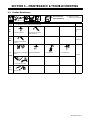
SECTION 1 − SAFETY PRECAUTIONS - READ BEFORE USING 1 . . . . . . . . . . . . . . . . . . . . . . . . . . . . . . . . . .
1-1. Symbol Usage 1 . . . . . . . . . . . . . . . . . . . . . . . . . . . . . . . . . . . . . . . . . . . . . . . . . . . . . . . . . . . . . . . . . . . . . . . .
1-2. Plasma Arc Cutting Hazards 1 . . . . . . . . . . . . . . . . . . . . . . . . . . . . . . . . . . . . . . . . . . . . . . . . . . . . . . . . . . . .
1-3. Additional Symbols For Installation, Operation, And Maintenance 3 . . . . . . . . . . . . . . . . . . . . . . . . . . . . .
1-4. California Proposition 65 Warnings 4 . . . . . . . . . . . . . . . . . . . . . . . . . . . . . . . . . . . . . . . . . . . . . . . . . . . . . . .
1-5. Principal Safety Standards 4 . . . . . . . . . . . . . . . . . . . . . . . . . . . . . . . . . . . . . . . . . . . . . . . . . . . . . . . . . . . . .
1-6. EMF Information 4 . . . . . . . . . . . . . . . . . . . . . . . . . . . . . . . . . . . . . . . . . . . . . . . . . . . . . . . . . . . . . . . . . . . . . .
SECTION 2 − CONSIGNES DE SÉCURITÉ − LIRE AVANT UTILISATION 5 . . . . . . . . . . . . . . . . . . . . . . . . . . .
2-1. Signification des symboles 5 . . . . . . . . . . . . . . . . . . . . . . . . . . . . . . . . . . . . . . . . . . . . . . . . . . . . . . . . . . . . .
2-2. Dangers liés au coupage à l’arc au plasma 5 . . . . . . . . . . . . . . . . . . . . . . . . . . . . . . . . . . . . . . . . . . . . . . . .
2-3. Dangers supplémentaires en relation avec l’installation, le fonctionnement
et la maintenance 7 . . . . . . . . . . . . . . . . . . . . . . . . . . . . . . . . . . . . . . . . . . . . . . . . . . . . . . . . . . . . . . . . . . . . .
2-4. Proposition californienne 65 Avertissements 8 . . . . . . . . . . . . . . . . . . . . . . . . . . . . . . . . . . . . . . . . . . . . . . .
2-5. Principales normes de sécurité 9 . . . . . . . . . . . . . . . . . . . . . . . . . . . . . . . . . . . . . . . . . . . . . . . . . . . . . . . . . .
2-6. Information EMF 9 . . . . . . . . . . . . . . . . . . . . . . . . . . . . . . . . . . . . . . . . . . . . . . . . . . . . . . . . . . . . . . . . . . . . . .
SECTION 3 − DEFINITIONS 10 . . . . . . . . . . . . . . . . . . . . . . . . . . . . . . . . . . . . . . . . . . . . . . . . . . . . . . . . . . . . . . . . . . .
3-1. Symbols And Definitions For Nameplate And Serial Number/Rating Label 10 . . . . . . . . . . . . . . . . . . . . . .
SECTION 4 − INSTALLATION 11 . . . . . . . . . . . . . . . . . . . . . . . . . . . . . . . . . . . . . . . . . . . . . . . . . . . . . . . . . . . . . . . . . .
4-1. Specifications 11 . . . . . . . . . . . . . . . . . . . . . . . . . . . . . . . . . . . . . . . . . . . . . . . . . . . . . . . . . . . . . . . . . . . . . . . .
4-2. Specifications For Torch 11 . . . . . . . . . . . . . . . . . . . . . . . . . . . . . . . . . . . . . . . . . . . . . . . . . . . . . . . . . . . . . . . .
4-3. Duty Cycle And Overheating 11 . . . . . . . . . . . . . . . . . . . . . . . . . . . . . . . . . . . . . . . . . . . . . . . . . . . . . . . . . . . .
4-4. Torch Dimensions And Weight 12 . . . . . . . . . . . . . . . . . . . . . . . . . . . . . . . . . . . . . . . . . . . . . . . . . . . . . . . . . .
4-5. Selecting A Location 12 . . . . . . . . . . . . . . . . . . . . . . . . . . . . . . . . . . . . . . . . . . . . . . . . . . . . . . . . . . . . . . . . . . .
4-6. Connecting Gas/Air Supply 13 . . . . . . . . . . . . . . . . . . . . . . . . . . . . . . . . . . . . . . . . . . . . . . . . . . . . . . . . . . . . .
4-7. Connecting Work Clamp 14 . . . . . . . . . . . . . . . . . . . . . . . . . . . . . . . . . . . . . . . . . . . . . . . . . . . . . . . . . . . . . . .
4-8. Connecting Input Power 14 . . . . . . . . . . . . . . . . . . . . . . . . . . . . . . . . . . . . . . . . . . . . . . . . . . . . . . . . . . . . . . . .
4-9. Installing Alternative Plug 15 . . . . . . . . . . . . . . . . . . . . . . . . . . . . . . . . . . . . . . . . . . . . . . . . . . . . . . . . . . . . . . .
SECTION 5 − OPERATION 16 . . . . . . . . . . . . . . . . . . . . . . . . . . . . . . . . . . . . . . . . . . . . . . . . . . . . . . . . . . . . . . . . . . . .
5-1. Controls 16 . . . . . . . . . . . . . . . . . . . . . . . . . . . . . . . . . . . . . . . . . . . . . . . . . . . . . . . . . . . . . . . . . . . . . . . . . . . . .
5-2. Cutting Speed 17 . . . . . . . . . . . . . . . . . . . . . . . . . . . . . . . . . . . . . . . . . . . . . . . . . . . . . . . . . . . . . . . . . . . . . . . .
5-3. Trigger Safety Lock 17 . . . . . . . . . . . . . . . . . . . . . . . . . . . . . . . . . . . . . . . . . . . . . . . . . . . . . . . . . . . . . . . . . . .
5-4. Sequence Of Operation 18 . . . . . . . . . . . . . . . . . . . . . . . . . . . . . . . . . . . . . . . . . . . . . . . . . . . . . . . . . . . . . . . .
SECTION 6 − MAINTENANCE & TROUBLESHOOTING 19 . . . . . . . . . . . . . . . . . . . . . . . . . . . . . . . . . . . . . . . . . . .
6-1. Routine Maintenance 19 . . . . . . . . . . . . . . . . . . . . . . . . . . . . . . . . . . . . . . . . . . . . . . . . . . . . . . . . . . . . . . . . . .
6-2. Overload Protection: Trouble Lights & Checking Shield Cup Shutdown System 20 . . . . . . . . . . . . . . . . . .
6-3. Torch And Work Cable Connections 21 . . . . . . . . . . . . . . . . . . . . . . . . . . . . . . . . . . . . . . . . . . . . . . . . . . . . . .
6-4. Checking/Replacing Retaining Cup, Tip, And Electrode 22 . . . . . . . . . . . . . . . . . . . . . . . . . . . . . . . . . . . . . .
6-5. Troubleshooting Power Source 23 . . . . . . . . . . . . . . . . . . . . . . . . . . . . . . . . . . . . . . . . . . . . . . . . . . . . . . . . . .
6-6. Troubleshooting Torch 24 . . . . . . . . . . . . . . . . . . . . . . . . . . . . . . . . . . . . . . . . . . . . . . . . . . . . . . . . . . . . . . . . .
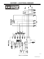
SECTION 7 − ELECTRICAL DIAGRAM 25 . . . . . . . . . . . . . . . . . . . . . . . . . . . . . . . . . . . . . . . . . . . . . . . . . . . . . . . . . .
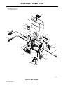
SECTION 8 − PARTS LIST 26 . . . . . . . . . . . . . . . . . . . . . . . . . . . . . . . . . . . . . . . . . . . . . . . . . . . . . . . . . . . . . . . . . . . . .
WARRANTY
Page is loading ...

OM-228 305 Page 1
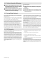
SECTION 1 − SAFETY PRECAUTIONS - READ BEFORE USING
pom _2007−04
Protect yourself and others from injury — read and follow these precautions.
1-1. Symbol Usage
DANGER! − Indicates a hazardous situation which, if
not avoided, will result in death or serious injury. The
possible hazards are shown in the adjoining symbols
or explained in the text.
Indicates a hazardous situation which, if not avoided,
could result in death or serious injury. The possible
hazards are shown in the adjoining symbols or ex-
plained in the text.
NOTICE − Indicates statements not related to personal injury.
. Indicates special instructions.
This group of symbols means Warning! Watch Out! ELECTRIC
SHOCK, MOVING PARTS, and HOT PARTS hazards. Consult sym-
bols and related instructions below for necessary actions to avoid the
hazards.
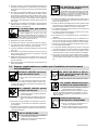
1-2. Plasma Arc Cutting Hazards
The symbols shown below are used throughout this manual
to call attention to and identify possible hazards. When you
see the symbol, watch out, and follow the related instructions
to avoid the hazard. The safety information given below is
only a summary of the more complete safety information
found in the Safety Standards listed in Section 1-5. Read and
follow all Safety Standards.
Only qualified persons should install, operate, maintain, and
repair this unit.
During operation, keep everybody, especially children, away.
CUTTING can cause fire or explosion.
Hot metal and sparks blow out from the cutting arc.
The flying sparks and hot metal, hot workpiece, and
hot equipment can cause fires and burns. Check
and be sure the area is safe before doing any cutting.
D Remove all flammables within 35 ft (10.7 m) of the cutting arc. If this
is not possible, tightly cover them with approved covers.
D Do not cut where flying sparks can strike flammable material.
D Protect yourself and others from flying sparks and hot metal.
D Be alert that sparks and hot materials from cutting can easily go
through small cracks and openings to adjacent areas.
D Watch for fire, and keep a fire extinguisher nearby.
D Be aware that cutting on a ceiling, floor, bulkhead, or partition can
cause fire on the hidden side.
D Do not cut on closed containers such as tanks or drums.
D Connect work cable to the work as close to the cutting area as prac-
tical to prevent cutting current from traveling long, possibly unknown
paths and causing electric shock, sparks, and fire hazards.
D Do not use plasma cutter to thaw frozen pipes.
D Never cut containers with potentially flammable materials inside −
they must be emptied and properly cleaned first.
D Do not cut where the atmosphere may contain flammable dust,
gas, or liquid vapors (such as gasoline).
D Do not cut pressurized cylinders, pipes, or vessels.
D Do not cut containers that have held combustibles.
D Wear oil-free protective garments such as leather gloves, heavy
shirt, cuffless trousers, high shoes, and a cap.
D Do not locate unit on or over combustible surfaces.
D Remove any combustibles, such as a butane lighter or matches,
from your person before doing any cutting.
D After completion of work, inspect area to ensure it is free of sparks,
glowing embers, and flames.
D Use only correct fuses or circuit breakers. Do not oversize or by-
pass them.
D Follow requirements in OSHA 1910.252 (a) (2) (iv) and NFPA 51B
for hot work and have a fire watcher and extinguisher nearby.
Touching live electrical parts can cause fatal shocks
or severe burns. The torch and work circuit are
electrically live whenever the output is on. The input
power circuit and machine internal circuits are also
live when power is on. Plasma arc cutting requires
higher voltages than welding to start and maintain the arc (200 to 400
volts dc are common), but may also use torches designed with safety
interlock systems which turn off the machine when the shield cup is
loosened or if tip touches electrode inside the nozzle. Incorrectly
installed or improperly grounded equipment is a hazard.
ELECTRIC SHOCK can kill.
D Do not touch live electrical parts.
D Wear dry, hole-free insulating gloves and body protection.
D Insulate yourself from work and ground using dry insulating mats or
covers big enough to prevent any physical contact with the work or
ground.
D Do not touch torch parts if in contact with the work or ground.
D Turn off power before checking, cleaning, or changing torch parts.
D Disconnect input power before installing or servicing this equip-
ment. Lockout/tagout input power according to OSHA CFR
1910.147 (see Safety Standards).
D Properly install and ground this equipment according to its Owner’s
Manual and national, state, and local codes.
D Check and be sure that input power cord ground wire is properly
connected to ground terminal in disconnect box or that cord plug is
connected to a properly grounded receptacle outlet − always verify
the supply ground.
D When making input connections, attach proper grounding conduc-
tor first.
D Keep cords dry, free of oil and grease, and protected from hot metal
and sparks.
D Frequently inspect input power cord for damage or bare wiring − re-
place cord immediately if damaged − bare wiring can kill.
D Turn off all equipment when not in use.
D Inspect and replace any worn or damaged torch cable leads.
D Do not wrap torch cable around your body.
D Ground the workpiece to a good electrical (earth) ground if required
by codes.
D Use only well-maintained equipment. Repair or replace damaged
parts at once.
D Wear a safety harness if working above floor level.
D Keep all panels and covers securely in place.
D Do not bypass or try to defeat the safety interlock systems.
D Use only torch(es) specified in Owner’s Manual.
D Keep away from torch tip and pilot arc when trigger is pressed.
D Clamp work cable with good metal-to-metal contact to workpiece
(not piece that will fall away) or worktable as near the cut as
practical.
D Insulate work clamp when not connected to workpiece to prevent
contact with any metal object.

OM-228 305 Page 2
SIGNIFICANT DC VOLTAGE exists in
inverter power sources AFTER the re-
moval of input power.
D Turn Off unit, disconnect input power, check voltage on input ca-
pacitors, and be sure it is near zero (0) volts before touching any
parts. Check capacitors according to instructions in Mainte-
nance Section of Owner’s Manual or Technical Manual before
touching any parts.
ELECTRIC SHOCK can kill.
D On inverter power sources, failed parts can ex-
plode or cause other parts to explode when
power is applied. Always wear a face shield
and long sleeves when servicing inverters.
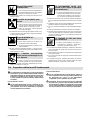
EXPLODING PARTS can injure.
Sparks and hot metal blow out from the cutting arc
.
Chipping and grinding cause flying metal.
FLYING SPARKS can cause injury.
D Wear approved face shield or safety goggles with side shields.
D Wear proper body protection to protect skin.
D Wear flame-resistant ear plugs or ear muffs to prevent sparks from
entering ears.
Arc rays from the cutting process produce intense
visible and invisible (ultraviolet and infrared) rays
that can burn eyes and skin.
ARC RAYS can burn eyes and skin.
D Wear face protection (helmet or shield) with a proper shade of filter
lenses to protect your face and eyes when cutting or watching. ANSI
Z49.1 (see Safety Standards) suggests a No. 9 shade (with No. 8 as
minimum) for all cutting currents less than 300 amperes. Z49.1 adds
that lighter filter shades may be used when the arc is hidden by the
workpiece. As this is normally the case with low current cutting, the
shades suggested in Table 1 are provided for the operator’s conve-
nience.
D Wear approved safety glasses with side shields under your helmet
or shield.
D Use protective screens or barriers to protect others from flash, glare
and sparks; warn others not to watch the arc.
D Wear protective clothing made from durable, flame-resistant
material (leather, heavy cotton, or wool) and foot protection.
Table 1. Eye Protection For Plasma Arc Cutting
Current Level In Amperes Minimum Shade Number
Below 20
20 − 40
40 − 60
60 − 80
#4
#5
#6
#8
Prolonged noise from some cutting applications can
damage hearing if levels exceed limits specified by
OSHA (see Safety Standards).
NOISE can damage hearing.
D Use approved ear plugs or ear muffs if noise level is high.
D Warn others nearby about noise hazard.
FUMES AND GASES can be hazardous.
Cutting produces fumes and gases. Breathing
these fumes and gases can be hazardous to
your health.
D Keep your head out of the fumes. Do not breathe the fumes.
D If inside, ventilate the area and/or use local forced ventilation at the
arc to remove cutting fumes and gases.
D If ventilation is poor, wear an approved air-supplied respirator.
D Read and understand the Material Safety Data Sheets (MSDSs)
and the manufacturer’s instruction for metals to be cut, coatings,
and cleaners.
D Work in a confined space only if it is well ventilated, or while wearing
an air-supplied respirator. Fumes from cutting and oxygen depletion
can alter air quality causing injury or death. Be sure the breathing air
is safe.
D Do not cut in locations near degreasing, cleaning, or spraying oper-
ations. The heat and rays of the arc can react with vapors to form
highly toxic and irritating gases.
D Do not cut on coated metals, such as galvanized, lead, or cadmium
plated steel, unless the coating is removed from the cutting area, the
area is well ventilated, and while wearing an air-supplied respirator.
The coatings and any metals containing these elements can give off
toxic fumes when cut.
D Do not cut containers with toxic or reactive materials inside or
containers that have held toxic or reactive materials − they must be
emptied and properly cleaned first.
PLASMA ARC can cause injury.
The heat from the plasma arc can cause serious
burns. The force of the arc adds greatly to the burn
hazard. The intensely hot and powerful arc can
quickly cut through gloves and tissue.
D Keep away from the torch tip.
D Do not grip material near the cutting path.
D The pilot arc can cause burns − keep away from torch tip when trig-
ger is pressed.
D Wear proper flame-retardant clothing covering all exposed body ar-
eas.
D Point torch away from your body and toward work when pressing
the torch trigger − pilot arc comes on immediately.
D Turn off power source and disconnect input power before disas-
sembling torch or changing torch parts.
D Use only torch(es) specified in the Owner’s Manual.
Gas cylinders contain gas under high pressure. If
damaged, a cylinder can explode. Since gas cylin-
ders are normally part of metalworking processes,
be sure to treat them carefully.
CYLINDERS can explode if damaged.
D Protect compressed gas cylinders from excessive heat, mechani-
cal shocks, physical damage, slag, open flame, sparks, and arcs.
D Install and secure cylinders in an upright position by chaining them
to a stationary support or equipment cylinder rack to prevent falling
or tipping.
D Keep cylinders away from any cutting or other electrical circuits.
D Never allow electrical contact between a plasma arc torch and a
cylinder.
D Never cut on a pressurized cylinder − explosion will result.
D Use only correct gas cylinders, regulators, hoses, and fittings de-
signed for the specific application; maintain them and associated
parts in good condition.
D Turn face away from valve outlet when opening cylinder valve.
D Keep protective cap in place over valve except when cylinder is in
use or connected for use.
D Use the right equipment, correct procedures, and sufficient number
of persons to lift and move cylinders.
D Read and follow instructions on compressed gas cylinders, asso-
ciated equipment, and Compressed Gas Association (CGA)
publication P-1 listed in Safety Standards.

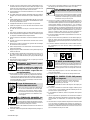
OM-228 305 Page 3
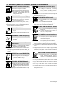
1-3. Additional Symbols For Installation, Operation, And Maintenance
HOT PARTS can cause severe burns.
D Do not touch hot parts bare handed.
D Allow cooling period before working on torch.
D To handle hot parts, use proper tools and/or
wear heavy, insulated welding gloves and
clothing to prevent burns.
MOVING PARTS can cause injury.
D Keep away from moving parts such as fans.
D Keep all doors, panels, covers, and guards
closed and securely in place.
D Have only qualified persons remove doors, panels, covers, or
guards for maintenance as necessary.
D Reinstall doors, panels, covers, or guards when maintenance is
finished and before reconnecting input power.
READ INSTRUCTIONS.
D Read Owner’s Manual before using or servic-
ing unit.
D Use only genuine replacement parts from the
manufacturer.
FLYING METAL or DIRT can injure eyes
.
D Wear safety glasses with side shields or wear
face shield.
MAGNETIC FIELDS can affect Implanted
Medical Devices.
D Wearers of Pacemakers and other Implanted
Medical Devices should keep away.
D Implanted Medical Device wearers should consult their doctor
and the device manufacturer before going near arc welding, spot
welding, gouging, plasma arc cutting, or induction heating
operations.
OVERUSE can cause OVERHEATING
.
D Allow cooling period; follow rated duty cycle.
D Reduce amperage (thickness) or reduce duty
cycle before starting to cut again.
EXPLODING HYDROGEN hazard.
D When cutting aluminum underwater or with the
water touching the underside of the aluminum,
free hydrogen gas may collect under the work-
piece.
D See your cutting engineer and water table instructions for help.
FALLING UNIT can cause injury.
D Use lifting eye to lift unit only, NOT running
gear, gas cylinders, or any other accessories.
D Use equipment of adequate capacity to lift unit.
D If using lift forks to move unit, be sure forks are long enough to ex-
tend beyond opposite side of unit.
FIRE OR EXPLOSION hazard.
D Do not locate unit on, over, or near combustible
surfaces.
D Do not install unit near flammables.
D Do not overload building wiring − be sure power supply system is
properly sized, rated, and protected to handle this unit.
STATIC (ESD) can damage PC boards.
D Put on grounded wrist strap BEFORE handling
boards or parts.
D Use proper static-proof bags and boxes to
store, move, or ship PC boards.
H.F. RADIATION can cause interference.
D High frequency (H.F.) can interfere with radio
navigation, safety services, computers, and
communications equipment.
D Have only qualified persons familiar with elec-
tronic equipment perform this installation.
D The user is responsible for having a qualified electrician promptly
correct any interference problem resulting from the installation.
D If notified by the FCC about interference, stop using the equipment
at once.
D Have the installation regularly checked and maintained.
D Keep high-frequency source doors and panels tightly shut, keep
spark gaps at correct setting, and use grounding and shielding to
minimize the possibility of interference.
ARC CUTTING can cause interference.
D Electromagnetic energy can interfere with
sensitive electronic equipment such as
computers and computer-driven equipment
such as robots.
D To reduce possible interference, keep cables as short as possible,
close together, and down low, such as on the floor.
D Locate cutting operation 100 meters from any sensitive electronic
equipment.
D Be sure this cutting power source is installed and grounded
according to this manual.
D If interference still occurs, the user must take extra measures such
as moving the machine, using shielded cables, using line filters, or
shielding the work area.

OM-228 305 Page 4
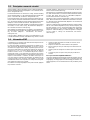
1-4. California Proposition 65 Warnings
Welding or cutting equipment produces fumes or gases
which contain chemicals known to the State of California to
cause birth defects and, in some cases, cancer. (California
Health & Safety Code Section 25249.5 et seq.)
Battery posts, terminals and related accessories contain lead
and lead compounds, chemicals known to the State of
California to cause cancer and birth defects or other
reproductive harm. Wash hands after handling.
For Gasoline Engines:
Engine exhaust contains chemicals known to the State of
California to cause cancer, birth defects, or other reproduc-
tive harm.
For Diesel Engines:
Diesel engine exhaust and some of its constituents are known
to the State of California to cause cancer, birth defects, and
other reproductive harm.
1-5. Principal Safety Standards
Safety in Welding, Cutting, and Allied Processes, ANSI Standard Z49.1,
from Global Engineering Documents (phone: 1-877-413-5184, website:
www.global.ihs.com).
Recommended Practices for Plasma Arc Cutting, American Welding
Society Standard AWS C5.2, from Global Engineering Documents
(phone: 1-877-413-5184, website: www.global.ihs.com).
Recommended Safe Practices for the Preparation for Welding and Cut-
ting of Containers That Have Held Hazardous Substances, American
Welding Society Standard AWS F4.1, from Global Engineering Docu-
ments (phone: 1-877-413-5184, website: www.global.ihs.com).
National Electrical Code, NFPA Standard 70, from National Fire Protec-
tion Association, P.O. Box 9101, Quincy, MA 02269-9101 (phone:
617-770-3000, website: www.nfpa.org and www. sparky.org).
Safe Handling of Compressed Gases in Cylinders, CGA Pamphlet P-1,
from Compressed Gas Association, 4221 Walney Road, 5th Floor,
Chantilly, VA 20151 (phone: 703-788-2700, website:www.cganet.com).
Code for Safety in Welding and Cutting, CSA Standard W117.2, from
Canadian Standards Association, Standards Sales, 5060 Mississauga,
Ontario, Canada L4W 5NS (phone: 800-463-6727 or in Toronto
416-747-4044, website: www.csa-international.org).
Safe Practice For Occupational And Educational Eye And Face Protec-
tion, ANSI Standard Z87.1, from American National Standards Institute,
25 West 43rd Street, New York, NY 10036–8002 (phone: 212-642-4900,
website: www.ansi.org).
Standard for Fire Prevention During Welding, Cutting, and Other Hot
Work, NFPA Standard 51B, from National Fire Protection Association,
P.O. Box 9101, Quincy, MA 02269-9101 (phone: 617-770-3000, web-
site: www.nfpa.org.
OSHA, Occupational Safety and Health Standards for General Industry,
Title 29, Code of Federal Regulations (CFR), Part 1910, Subpart Q, and
Part 1926, Subpart J, from U.S. Government Printing Office, Superin-
tendent of Documents, P.O. Box 371954, Pittsburgh, PA 15250-7954
(phone: 1-866-512-1800) (there are 10 Regional Offices—phone for Re-
gion 5, Chicago, is 312-353-2220, website: www.osha.gov).
1-6. EMF Information
Considerations About Welding Or Cutting And The Effects Of Low
Frequency Electric And Magnetic Fields
Welding or cutting current, as it flows through the welding or cutting
cables, will cause electromagnetic fields. There has been and still is
some concern about such fields. However, after examining more than
500 studies spanning 17 years of research, a special blue ribbon
committee of the National Research Council concluded that: “The body
of evidence, in the committee’s judgment, has not demonstrated that
exposure to power-frequency electric and magnetic fields is a human-
health hazard.” However, studies are still going forth and evidence
continues to be examined. Until the final conclusions of the research are
reached, you may wish to minimize your exposure to electromagnetic
fields when welding or cutting.
To reduce magnetic fields in the workplace, use the following proce-
dures:
1. Keep cables close together by twisting or taping them, or using a
cable cover.
2. Arrange cables to one side and away from the operator.
3. Do not coil or drape cables around your body.
4. Keep cutting power source and cables as far away from operator
as practical.
5. Connect work clamp to workpiece as close to the cut as possible.
About Implanted Medical Devices:
Implanted Medical Device wearers should consult their doctor and the
device manufacturer before performing or going near arc welding, spot
welding, gouging, plasma arc cutting, or induction heating operations.
If cleared by your doctor, then following the above procedures is recom-
mended.
Page is loading ...
Page is loading ...
Page is loading ...
Page is loading ...

OM-228 305 Page 9
2-5. Principales normes de sécurité
Safety in Welding, Cutting, and Allied Processes, ANSI Standard Z49.1,
de Global Engineering Documents (téléphone : 1-877-413-5184, site In-
ternet : www.global.ihs.com).
Recommended Practices for Plasma Arc Cutting, American Welding
Society Standard AWS C5.2, de Global Engineering Documents (télé-
phone : 1-877-413-5184, site Internet : www.global.ihs.com).
Recommended Safe Practice for the Preparation for Welding and Cut-
ting of Containers That Have Held Hazardous Substances, norme AWS
F4.1, de l’American Welding Society de Global Engineering Documents
(téléphone : 1-877-413-5184, site Internet : www.global.ihs.com).
National Electrical Code, NFPA Standard 70, de National Fire Protection
Association, P.O. Box 9101, Quincy, MA 02269-9101 (téléphone :
617-770-3000, site Internet : www.nfpa.org).
Safe Handling of Compressed Gases in Cylinders, CGA Pamphlet P-1,
de Compressed Gas Association, 4221 Walney Road, 5th Floor, Chan-
tilly, VA 20151 (téléphone : 703-788-2700, site Internet :
www.cganet.com).
Code for Safety in Welding and Cutting, CSA Standard W117.2, de
Canadian Standards Association, 5060 Mississauga, Ontario, Canada
L4W 5NS (téléphone : 800-463-6727 ou à Toronto 416-747-4044, site
Internet : www.csa-international.org).
Safe Practice For Occupational And Educational Eye And Face Protec-
tion, ANSI Standard Z87.1, de American National Standards Institute,
11 West 43rd Street, New York, NY 10036-8002 (téléphone :
212-642-4900, site Internet : www.ansi.org).
Standard for Fire Prevention During Welding, Cutting, and Other Hot
Work, NFPA Standard 51B, de National Fire Protection Association,
P.O. Box 9101, Quincy, MA 02269-9101 (téléphone : 617-770-3000, site
Internet : www.nfpa.org).
OSHA, Occupational Safety and Health Standards for General Industry,
Title 29, Code of Federal Regulations (CFR), Part 1910, Subpart Q, and
Part 1926, Subpart J, de U.S. Government Printing Office, Superinten-
dent of Documents, P.O. Box 371954, Pittsburgh, PA 15250-7954
(téléphone : 1-866-512-1800) (il y a 10 bureaux régionaux−−le télépho-
ne de la région 5, Chicago, est 312-353-2220, site Internet :
www.osha.gov).
2-6. Information EMF
Considérations sur le soudage et les effets de basse fréquence et des
champs magnétiques et électriques.
Le courant de soudage, pendant son passage dans les câbles de sou-
dage, causera des champs électromagnétiques. Il y a eu et il y a encore
un certain souci à propos de tels champs. Cependant, après avoir exa-
miné plus de 500 études qui ont été faites pendant une période de
recherche de 17 ans, un comité spécial ruban bleu du National
Research Council a conclu : « L’accumulation de preuves, suivant le
jugement du comité, n’a pas démontré que l’exposition aux champs
magnétiques et champs électriques à haute fréquence représente un
risque à la santé humaine ». Toutefois, des études sont toujours en
cours et les preuves continuent à être examinées. En attendant que les
conclusions finales de la recherche soient établies, il vous serait
souhaitable de réduire votre exposition aux champs électromagnéti-
ques pendant le soudage ou le coupage.
Pour réduire les champs magnétiques sur le poste de travail, appliquer
les procédures suivantes :
1. Garder les câbles ensemble, les torsader, les scotcher, ou les
recouvrir d’une housse.
2. Disposer les câbles d’un côté et à distance de l’opérateur.
3. Ne pas courber pas et ne pas entourer pas les câbles autour de
votre corps.
4. Garder le poste de soudage et les câbles le plus loin possible de
vous.
5. Connecter la pince sur la pièce aussi près que possible de la
soudure.
En ce qui concerne les implants médicaux :
Les porteurs d’implants doivent d’abord consulter leur médecin avant de
s’approcher des opérations de soudage à l’arc, de soudage par points,
de gougeage, du coupage plasma ou de chauffage par induction. Si le
médecin approuve, il est recommandé de suivre les procédures précé-
dentes.

OM-228 305 Page 10
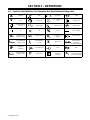
SECTION 3 − DEFINITIONS
3-1. Symbols And Definitions For Nameplate And Serial Number/Rating Label
A
Amperes
Plasma Arc Cutting
(PAC)
Adjust Air/Gas
Pressure
Low Air Pressure
Light
V
Volts Increase
No − Do Not Do
This
Temperature
Protective Earth
(Ground)
Single Phase Constant Current Voltage Input
On Off Percent Direct Current
U
0
Rated No Load
Voltage (Average)
U
1
Primary Voltage
U
2
Conventional Load
Voltage
Line Connection
I
1max
Rated Maximum
Supply Current
I
2
Rated Welding
Current
X
Duty Cycle
1 f1
f2
Single Phase
Static Frequency
Transformer-
Rectifier-Converter
IP
Degree Of
Protection
Loose Shield Cup Input
Hz
Hertz
I
1eff
Maximum Effective
Supply Current
pf
power factor
S
Suitable for Some
Hazardous
Locations
S
1
Power Rating,
Product Of Voltage
And Current (KVA)

OM-228 305 Page 11
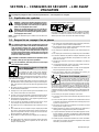
SECTION 4 − INSTALLATION
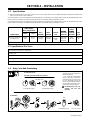
4-1. Specifications
. If the unit is operated from a 30* ampere, 115 volt circuit or a 15** ampere, 230 volt circuit, a different input power plug must be installed on the
power cord. See Section 4-9 for instructions.
*A 30 ampere branch circuit is recommended for maximum performance. Performance on a 20 ampere branch service may be limited due to the circuit
breaker or line fuse. Reducing unit output amperage will minimize circuit breaker tripping or blowing a line fuse.
**A 15 ampere branch circuit is recommended for maximum performance. Performance on a 10 ampere branch service may be limited due to the circuit
breaker or line fuse. Reducing unit output amperage will minimize circuit breaker tripping or blowing a line fuse.
Amperes Input at
Rated Output,
60 Hz, Single-Phase
Plasma
Rated
Cutting
Rated Output
115 V
(+15%)
230 V
(+15%)
115 V
KVA/KW
230 V
KVA/KW
Plasma
Gas
Plasma
Gas Flow
/
Pressure
Cutting
Capacity
at 10 IPM
Max
OCV
27 A at 92 Volts DC At
35% Duty Cycle
28 max;
0.30*
14 max;
0.13*
3.32 KVA
3.25 KW
3.25 KVA
3.19 KW
Air Or
Nitrogen
Only
4.5 CFM
(129 L/min)
At 60 PSI
(414 kPa)
3/8 in
(10 mm)
288 Volts
DC
*While idling
4-2. Specifications For Torch
Air-cooled torch for plasma arc cutting (PAC)
35% duty cycle
Safety interlock devices shut down power source
Safety trigger guard
Cutting capacity: see Section 4-1
4-3. Duty Cycle And Overheating
Duty Cycle is percentage of 10 min-
utes that unit can cut at rated load
without overheating.
If unit overheats, thermostat(s)
opens, output stops, Temperature
trouble light goes On, and cooling
fan runs. Wait fifteen minutes for
unit to cool or temperature light to
go off. Reduce amperage or duty
cycle before cutting or gouging.
! Exceeding duty cycle can
damage unit and void
warranty.
Overheating
sduty1 5/95 / 804 486-A
3-1/2 Minutes Cutting 6-1/2 Minutes Resting
35% duty cycle
For Units Connected to a 115 Volt Circuit
or a 230 Volt Circuit:
35% Duty Cycle At 27 amperes, 92 volts dc
0
15
Minutes
A
OR
Reduce Duty Cycle

OM-228 305 Page 12
4-4. Torch Dimensions And Weight
Ref. 802 877
3.0 lb (1.4 kg)
1 in
(25 mm)
8-3/8 in
(213 mm)
1-3/8 in
(35 mm)
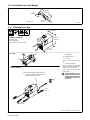
4-5. Selecting A Location
loc_2 3/96 - Ref. 804 486-A / 804 487-A / 804 488-A
1 Lifting Handle
Use handle to lift unit.
2 Hand Cart
Use cart or similar device to move
unit.
3 120 VAC Receptacle
To connect unit to 230 VAC input
power, a customer supplied plug is
necessary (see Section 4-9).
Locate unit near correct input
power supply.
! Special installation may be
required where gasoline or
volatile liquids are present −
see NEC Article 511 or CEC
Section 20.
Movement
Location And Airflow
Dimensions And Weight
49 lb (22.2 kg)
not including torch
*Add 13/16 in (21 mm) for handle.
16 in
(406 mm)
8-1/2 in
(216 mm)
12-5/16 in*
(313 mm)
1
2
10 in
(254 mm)
10 in
(254 mm)
. Serial Number/Rating Label located on
rear panel of plasma cutter; use label to
determine input power for unit.
3

OM-228 305 Page 13
4-6. Connecting Gas/Air Supply
802 787-A / Ref. 801 319-C / Ref. 804 486-A
. Use only clean, dry air with 90
to 120 psi (621 to 827 kPa)
pressure.
1 Gas/Air Inlet Opening
2 Hose
3 Teflon Tape
Obtain hose with 1/4 NPT right-
hand thread fitting. Wrap threads
with teflon tape (optional) or apply
pipe sealant, and install fitting in
opening. Route hose to gas/air
supply.
4 Air Filter/Regulator
Adjust gas/air pressure according
to Section 5-1.
Tools Needed:
5/8, 1-1/8 in
3
1
2
From Gas/Air
Supply
4

OM-228 305 Page 14
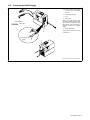
4-7. Connecting Work Clamp
802 463-A
1 Work Clamp
2 Workpiece
Connect work clamp to a clean,
paint-free location on workpiece, as
close to cutting area as possible.
1
2
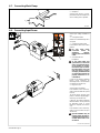
4-8. Connecting Input Power
Ref. 802 787-A / 804 488-A
Check input voltage available at
site.
1 Changeover Switch
Switch is accessible through slot in
rear panel.
2 Changeover Switch Label
Look at label to find correct switch
position.
! Be sure input power
connection meets all
applicable national,
regional, and local electrical
codes.
3 Grounded 120 VAC
Receptacle
! To use rated output (see
specifications), connect the
unit to an individual branch
circuit capable of carrying
the effective (eff) current for
the output being used. The
unit must have a properly
sized plug installed and the
circuit must be protected by
properly sized fuses or cir-
cuit breakers.
A 120 volt, 20 ampere individual
branch circuit protected by
time-delay fuses or circuit breaker
is required (see Section 4-1).
4 Plug From Unit
Connect plug to receptacle.
If an extension cord is necessary,
select a cord of 12 AWG for up to 53
ft (16 m).
To connect unit to 230 VAC input
power, a customer supplied plug is
necessary (see Section 4-9).
A 230 volt, 15 ampere (minimum)
individual branch circuit protected
by time-delay fuses or circuit
breaker is required (see Section
4-1).
If an extension cord is necessary,
select a cord of 14 AWG for up to
133 ft (41 m).
! Special installation may be
required where gasoline or
volatile liquids are present −
see NEC Article 511 or CEC
Section 20.
2
1
4
3

OM-228 305 Page 15
4-9. Installing Alternative Plug
1 Supplied 115 VAC Plug
Cut cord close to plug.
2 Alternative PLug (230 VAC
Plug Shown)
3 Load 1 (Brass) Terminal
4 Load 2 (Brass) Terminal
5 Ground (Green) Terminal
6 Outer Shell
7 Cord Grip
Strip cord jacket back enough to
separate conductors. Strip conduc-
tors enough to make good contact
with plug terminals. Make plug con-
nections and reinstall outer shell and
cord grip. Tighten assembly screws
onto shell. Do not overtighten.
Ref. 801 305-A / 801 611
. This procedure is necessary if the unit is to be connected to a 230 VAC receptacle,
or to a 115 VAC receptacle that requires a plug that is different from the supplied plug.
Tools Needed:
1
6
7
2
3
4
5
. See Section 4-8 for instructions on setting changeover switch for proper voltage.

OM-228 305 Page 16
SECTION 5 − OPERATION
5-1. Controls
1
423
ON
OFF
PRESSURE
60 PSI
5
6
24
27
20
16
24
27
20
16
1
24
27
20
16
Requires
90-120 PSI
(621-827 kPa)
Supply
Setting Gas/Air Pressure
1 Output Control
Use control to set cutting output.
Place control in Gas/Air Set position to safely
adjust gas/air pressure. Only gas/air circuit
is activated.
If 22-27 amperes of cutting output is used
with 115 VAC input power, and the overload
protection on the input power circuit fre-
quently opens, either reduce the cutting out-
put and/or the cut time or find more adequate
power (see Section 4-1).
2 Trouble Lights (See Section 6-2)
3 Power Light
4 Power Switch
Setting Gas/Air Pressure
5 Air Filter/Regulator
6 Pressure Adjustment Knob
Place Output control in Gas/Air position and
turn on gas/air supply. Lift knob and turn to
adjust pressure. Push knob down to lock in
setting.
Place Output control in desired cutting
output.
. At ambient temperatures below −55 C
(235 F), readjustment of gas/air
pressure regulator may be necessary.
Ref. 227 835-A / Ref. 804 486-A
5
6
Set To
60 PSI (414 kPa)

OM-228 305 Page 17
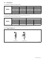
5-2. Cutting Speed
Recommended Cut Speeds At 27 Amperes Output
Thickness Recommended Cut Speeds*
Inches mm ipm mm/min
Mild Steel
16 ga 1.5 188 4,775
Mild Steel
3/16 4.8 40 1,016
1/4 6.4 24 610
3/8 9.5 14 256
1/2 12.7 6 152
*Recommended Cut Speed is approximately 80% of maximum.
. Aluminum and Stainless Steel cut speeds at these thicknesses may be reduced as much as 20%.
Recommended Cut Speeds At 20 Amperes Output
Thickness Recommended Cut Speeds*
Inches mm ipm mm/min
Mild Steel
16 ga 1.5 162 4,115
Mild Steel
3/16 4.8 26 660
1/4 6.4 18 457
3/8 9.5 7 178
*Recommended Cut Speed is approximately 80% of maximum.
. Aluminum and Stainless Steel cut speeds at these thicknesses may be reduced as much as 20%.
5-3. Trigger Safety Lock
Trigger Locked Trigger Unlocked
1 Trigger
802 877
1

OM-228 305 Page 18
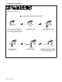
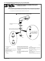
out bottom of cut.
Ref. 802 878
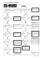
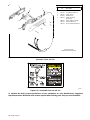
5-4. Sequence Of Operation
After cutting arc starts, slowly
start moving torch across metal.
Adjust torch speed so
sparks go thru metal and
Pause briefly at end of
cut before releasing trigger.
EXAMPLE Of Cutting Operation
Raise trigger lock and press
trigger. Pilot arc starts.
Postflow continues for 20 seconds after
releasing trigger; cutting arc can be instantly
restarted during postflow by raising trigger
lock and pressing trigger.
! The pilot arc starts immediately when trigger is pressed.
Place tip on work for drag cutting or for
maximum cutting speed and tip life, use a
standoff distance of 1/16 in (1.6 mm) to 1/8
in (3.2 mm) (dragging tip will reduce tip life).

OM-228 305 Page 19
SECTION 6 − MAINTENANCE & TROUBLESHOOTING
6-1. Routine Maintenance
! Disconnect power
before maintaining.
. Maintain more often
during severe conditions
.
n = Check Z = Change ~ = Clean l = Replace
* To be done by Factory Authorized Service Agent
Reference
Each
Use
Section 4-6
,
6-4
Use
n Gas/Air Pressure n Torch Tip, Electrode,
And Shield Cup
6-4
Every
Week
Section 6-2
Week
n Shield Cup Shutdown
System
Section 6-2
Every
3
Months
l Damaged Or Unreadable
Labels
~ Air Filter/Regulator l Cracked Parts n l Gas/Air Hose
Section 8
Months
Section 8
n l Torch Body, Cable
Every
6
Months
OR
Months
~ Inside Unit

OM-228 305 Page 20
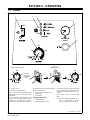
6-2. Overload Protection: Trouble Lights & Checking Shield Cup Shutdown System
If certain problems occur, the
Ready light goes off, a trouble light
comes on, and output stops.
1 Pressure Light
Lights if gas/air pressure is below
40 PSI (276 kPa).
Turn power Off, and check for
proper gas/air pressure (see
Section 5-1).
A flashing Pressure light indicates
that gas/air system may be set too
low, faulty, leaking or has a flow re-
striction (see Section 6-5).
2 Cup Light
Lights if shield cup is loose.
Turn power Off, and check shield
cup connection (see torch Owner’s
Manual). Power must be reset
whenever the cup shutdown is
activated.
A flashing Cup light indicates that
the torch consumables are stuck or
worn and should be inspected and/
or replaced (see Section 6-4).
Check shield cup shutdown system
once a week.
3 Temperature Light
Lights if power source overheats or
when ambient temperature is below
−35° C (−31° F) (see Section 4-3).
4 Torch Shield Cup
Turn Power On and loosen shield
cup. If shutdown system works
properly, Ready light goes off and
Cup light comes on. If not, turn
power Off and check for proper
gas/air pressure (see Section 4-1),
blocked or leaking hose, or loose
shield cup (see torch Owner’s
Manual).
If system works properly, retighten
cup and reset power.
Ref. 200 808 / Ref. 802 877
Checking Torch Shield Cup Shutdown System
. Power must be reset whenever the cup shutdown system is activated.
Always turn Off power when changing or checking consumables.
Do NOT overtighten torch shield cup. Gently finger tighten cup
onto torch.
1
2
3
4

OM-228 305 Page 21
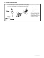
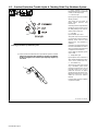
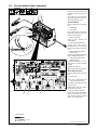
6-3. Torch And Work Cable Connections
If torch or work cable needs to be
removed or replaced, proceed as
follows:
Turn power Off, and disconnect
input power plug from receptacle.
Remove wrapper from unit.
Torch Connections
Remove existing torch cable from
unit.
1 Strain Relief
2 Torch Cable
Insert cable through strain relief.
Slide strain relief nut onto torch
cable, but do not tighten.
3 Air Line Connector
Insert air line connector into
solenoid fitting.
4 Plug PLG1/Receptacle RC1
Connect PLG1 from torch to
receptacle RC1 on end of wiring
harness connected to circuit board
PC1.
5 Ring Terminal And TORCH
RED Terminal
Connect ring terminal on end of red
leads to TORCH RED terminal.
6 Ring Terminal And TORCH
WHITE Terminal
Connect ring terminal on end of
white leads to TORCH WHITE
terminal.
Tighten strain relief nut.
Tighten strain relief around cable.
Work Cable Connections
Remove existing work cable from
unit.
7 Work Cable
. Be sure to allow some work
cable slack inside the unit.
Insert work cable with strain relief
into front panel.
Tighten strain relief nut. Tighten
strain relief around cable.
8 Work Cable Ring Terminal
Route cable under center baffle.
Connect ring terminal on end of
work cable to terminal labeled
WORK on circuit board PC1.
Tools Needed:
804 489-B / Ref. 802 860 / 226 678-C
3
2
4
6
5
1/4 in
3
4
2
7
5
8
6
1
4
86 5

OM-228 305 Page 22
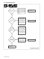
6-4. Checking/Replacing Retaining Cup, Tip, And Electrode
! Overtightening will strip threads. Do not overtighten retaining cup during
assembly. Do not cross-thread parts causing stripping. Use care during torch
assembly and parts replacement.
! Inspect shield cup, tip, and electrode for wear before cutting or whenever cutting speed has been significantly
reduced. Do not operate torch without a tip or electrode in place. Be sure to use genuine replacement parts.
. A good practice is to replace both the tip and electrode at the same time.
802 465
Turn Off power source.
1 Shield Cup
2 O-Ring
Remove shield cup. Check cup for cracks,
and replace if necessary.
Check O-ring for cracks or worn spots, re-
place shield cup if necessary.
3Tip
4 Opening
Remove tip. Check tip, and replace if open-
ing is deformed or 50% oversize. If inside of
tip is not clean and bright, clean with steel
wool. Be sure to remove any pieces of steel
wool afterwards.
5 Electrode
Check electrode. If center has a pit more
than a 1/16 in (2 mm) deep, remove and re-
place electrode.
6 Swirl Ring
7 O-Ring
Remove swirl ring. Check ring, and replace
if side holes are plugged.
Check O-ring for cracks or worn spots,
replace swirl ring if necessary.
8 O-Ring
Check O-ring for cracks or worn spots, and
replace if necessary.
Carefully reassemble parts in reverse order.
Make sure this area is clean of
any debris.
Make sure swirl ring is clean of any
debris and no holes are obstructed.
! Turn Off power source before checking torch parts.
New
Worn
4
3
6
1
2
7
8
New
Worn
5
1/32 in (1 mm) to 1/16 in
(2 mm) maximum pit
depth depending on
acceptable cut quality
Page is loading ...
Page is loading ...
Page is loading ...
Page is loading ...
Page is loading ...
Page is loading ...
Page is loading ...
Page is loading ...
Page is loading ...
Page is loading ...
-
 1
1
-
 2
2
-
 3
3
-
 4
4
-
 5
5
-
 6
6
-
 7
7
-
 8
8
-
 9
9
-
 10
10
-
 11
11
-
 12
12
-
 13
13
-
 14
14
-
 15
15
-
 16
16
-
 17
17
-
 18
18
-
 19
19
-
 20
20
-
 21
21
-
 22
22
-
 23
23
-
 24
24
-
 25
25
-
 26
26
-
 27
27
-
 28
28
-
 29
29
-
 30
30
-
 31
31
-
 32
32
-
 33
33
-
 34
34
-
 35
35
-
 36
36


AUTO ARC AUTO ARC QUICK CUT 4500 AND ICE-27C TORCH User manual
- Category
- Welding System
- Type
- User manual
Ask a question and I''ll find the answer in the document
Finding information in a document is now easier with AI
in other languages
Related papers
Other documents
-
Miller LG030149P Owner's manual
-
HobartWelders AIRFORCE 400 & ICE-27C TORCH Owner's manual
-
-
Miller Electric ICE-27T User manual
-
-
Miller CST 280 Owner's manual
-
Hobart Welding Products HP-25 TORCH User manual
-
-
-