Electro-Voice PA4150L User manual
- Category
- Audio amplifiers
- Type
- User manual

OWNER‘S MANUAL
BEDIENUNGSANLEITUNG
MODE D‘EMPLOI
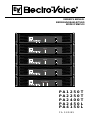
PA1250T
PA2250T
PA2400T
PA2450L
PA4150L
PA SERIES

CONTENTS
ENGLISH
IMPORTANT SAFETY INSTRUCTIONS ...... 3
IMPORTANT SERVICE INSTRUCTIONS ...... 3
DESCRIPTION ...... 4
Unpacking & Warranty ...... 4
Installation Notes ...... 4
FRONT PANEL ...... 5
Mains Switch ...... 5
Protect ...... 5
Limiter ...... 5
Level Indication ...... 5
Power ...... 5
REAR PANEL ...... 6
Audio Signal Inputs ...... 6
Level Controls ...... 6
Mode Switch ...... 6
High Pass Filter ...... 6
Loudspeaker Outputs ...... 7
Mains Fuse ...... 8
Mains Socket ...... 8
Voltage Selector ...... 8
LF CONNECTION CORDS ...... 8
MAINS OPERATION & RESULTING
TEMPERATURE ...... 9
NOTES ...... 11
DEUTSCH
INHALT ...... 12
WICHTIGE SICHERHEITSHINWEISE ...... 13
WICHTIGE SERVICEHINWEISE ...... 13
BESCHREIBUNG ...... 14
Auspacken & Garantie ...... 14
Installationshinweise ...... 14
FRONTSEITE ...... 15
Netzschalter ...... 15
Protect ...... 15
Limiter ...... 15
Pegelanzeigen ...... 15
Power ...... 15
RÜCKSEITE ...... 16
Signaleingänge ...... 16
Level Regler ...... 16
Mode Schalter ...... 16
Hochpasslter ...... 16
Lautsprecherausgänge ...... 17
Netzsicherung ...... 18
Netzbuchse ...... 18
Spannungswahlschalter ...... 18
NF-VERBINDUNGSKABEL ...... 18
NETZBETRIEB & WÄRMEENTWICKLUNG ...... 19
NOTIZEN ...... 21
2
FRANCAISE
TABLE DES MATIÉRES ...... 22
INSTRUCTIONS DE SÉCURITÉ
IMPORTANTES ...... 23
INSTRUCTIONS DE RÉPARATION
IMPORTANTES ...... 23
INTRODUCTION ...... 24
Déballage et garantie ...... 24
Remarques concernant l’installation ...... 24
FACE AVANT ...... 25
Interrupteur secteur ...... 25
Protect ...... 25
Limiteur ...... 25
Indicateur de niveau ...... 25
Power ...... 25
PANNEAU ARRIÈRE ...... 26
Entrées Signal Audio ...... 26
Contrôles de niveau ...... 26
Sélecteur de Mode ...... 26
Filtre Passe-Haut ...... 26
Sorties Haut-Parleur ...... 27
Fusible secteur ...... 28
Prise secteur ...... 28
Sélecteur de tension ...... 28
CORDONS DE CONNEXION AUDIO ...... 28
ALIMENTATION SECTEUR ET
TEMPÉRATURE RÉSULTANTE ...... 29
NOTICES ...... 31
APPENDIX / ANHANG / APPENDICE
TECHNICAL SPECIFICATIONS ...... 32
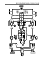
BLOCK DIAGRAMM ...... 33
PA2450L / PA4150L ...... 33
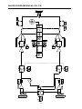
PA4150L ...... 34
PA2400T / PA2250T ...... 35
PA1250T ...... 36
DIMENSIONS ...... 37

3
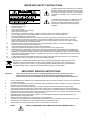
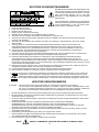
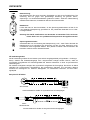
The lightning ash with arrowhead symbol, within an
equilateral triangle is intended to alert the user to the
presence of uninsulated „dangerous voltage“ within
the product’s enclosure that may be of sufcient
magnitude to constitute a risk of electric shock to
persons.
The exclamation point within an equilateral triangle
is intended to alert the user to the presence of
important operating and maintance (servicing)
instructions in the literature accompanying the
appliance.
1. Read these instructions.
2. Keep these instructions.
3. Heed all warnings.
4. Follow all instructions.
5. Do not use this apparatus near water.
6. Clean only with a dry cloth.
7. Do not cover any ventilation openings. Install in accordance with the manufacture’s instructions.
8. Do not install near heat sources such as radiators, heat registers, stoves, or other apparatus
(including ampliers) that produce heat.
9. Do not defeat the safety purpose of the polarized or the grounding-type plug. A polarized plug has two blades
with one wider than the other. A grounding type plug has two blades and a third grounding prong. The wide
blade or the third prong are provided for your safety. If the provided plug does not t into your outlet, consult an
electrican for replacement of the obsolete outlet.
10. Protect the power cord from being walked on or pinched particularly at plugs, convenience receptacles,
and the point where they exit from the apparatus.
11. Only use attachments/accessories specied by the manufacturer.
12. Unplug this apparatus during lightning storms or when unused for a long period of time.
13. Refer all servicing to qualied service personnel. Servicing is required when the apparatus has been damaged
in any way, such as power-supply cord or plug is damaged, liquid has been spilled or objects have fallen into the
apparatus, the apparatus has been exposed to rain or moisture, does not operate normally, or has been dropped.
14. Do not expose this equipment to dripping or splashing and ensure that no objects lled with liquids, such as vases,
are placed on the equipment.
15. To completely disconnect this equipment from the AC Mains, disconnect the power plug from the AC receptacle.
16. The mains plug of the power supply cord shall remain readily operable.
CAUTION: These servicing instructions are for use by qualied personnel only. To reduce the risk of
electric shock, do not perform any servicing other than that contained in the Operating
Instructions unless you are qualied to do so. Refer all servicing to qualied service personnel.
1. Security regulations as stated in the EN 60065 (VDE 0860 / IEC 65) and the CSA E65 - 94 have to be obeyed when
servicing the appliance.
2. Use of a mains separator transformer is mandatory during maintenance while the appliance is opened, needs to be
operated and is connected to the mains.
3. Switch off the power before retrotting any extensions, changing the mains voltage or the output voltage.
4. The minimum distance between parts carrying mains voltage and any accessible metal piece (metal enclosure),
respectively between the mains poles has to be 3 mm and needs to be minded at all times. The minimum distance
between parts carrying mains voltage and any switches or breakers that are not connected to the mains (secondary
parts) has to be 6 mm and needs to be minded at all times.
5. Replacing special components that are marked in the circuit diagram using the security symbol (Note) is only
permissible when using original parts.
6. Altering the circuitry without prior consent or advice is not legitimate.
7. Any work security regulations that are applicable at the location where the appliance is being serviced have to be
strictly obeyed. This applies also to any regulations about the work place itself.
8. All instructions concerning the handling of MOS - circuits have to be observed.
SAFETY COMPONENT ( MUST BE REPLACED BY ORIGINAL PART )NOTE:
IMPORTANT SERVICE INSTRUCTIONS
IMPORTANT SAFETY INSTRUCTIONS
Management of WEEE (waste electrical and electronic equipment) (applicable in Member States of the
European Union and other European countries with individual national policies on the management of
WEEE) The symbol on the product or on its packaging indicates that this product may not be treated as
regular household waste, but has to be disposed through returning it at a Telex dealer.

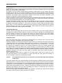
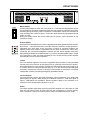
Congratulations on your ElectroVoice PA series power amplier purchase! The ElectroVoice PA-Series
power amp line combines outstanding audio performance, exceptional reliability and secure operational
safety in a compact 2RU chassis design.
All models in the PA Series provide several protection circuits which not only prevent the power
amplier itself but also the connected loudspeaker systems from being damaged. These protections
include Dynamic Audio Limiters, Inrush Current Limiter, Short Circuit Protection and Thermal Overload
Protection. All PA-Series power amps feature different hi-pass lters with switch selectable cut-off
frequency to attenuate unwanted low-frequency signals.
Innitely variable low-noise high performance fans guarantee absolute thermal stability while keeping fan
noise to a minimum. Direct “ow-thru” chassis design allows for a smooth ow of air from front-to-rear,
which allows trouble-free operation even in smaller amp-racks.
Compact high density power supply units with low-leakage toroidal transformers provide extensive
headroom far above the listed power rating. Premium phoenix style screw-lock connectors prevent
accidental disconnection resulting in a more secure connection of audio signal and speaker cables.
All PA series “T” version models are equipped with high performance output transformers also provide
oating outputs for 50V, 70V and 100V installations. These models also provide voltage limiters to
protect the loudspeaker outputs against over-voltage.
Unpacking & Warranty
Carefully open the packaging and take out the power amplier. Next to the power amplier itself, the
package also includes this owner’s manual, a mains cord, a warranty certicate, four attachable feet as
well as screwlock connectors for all inputs and outputs. The warranty period is 36 months starting
from the date when receiving the appliance from the dealer. Keep the original invoice, which states
the purchase/delivery date together with the warranty certicate at a safe place.
Installation Notes
First of all, please make sure to check that the voltage selector on the amp’s rear is set to the correct
position matching the installation site’s local mains voltage.
Generally, installing or mounting power amps should be carried out in a way that guarantees continuously
unopposed front-to-rear air circulation. When including an appliance in a closed cabinet or rack shelf
system make sure to provide sufcient ventilation. Leave an air duct of at least 2.5“ x 13“ (up to
the cabinet’s top ventilation louvers) for air circulation between the rear of the power amplier and
the cabinet’s/rack’s rear wall. Make sure to leave at least 4“ of space above the cabinet or rack
shelf system. Since temperatures inside of a cabinet or rack shelf system can easily rise up to 105 degrees
during operation, carefully considering the environmental temperature maximum values of all other
appliances installed in the same rack shelf system is mandatory (also refer to “Mains Operation &
Resulting Temperature”).
When installing the power amp in a cabinet or rack shelf system, make sure to make use of the
rear mounting facilities to x the appliance in place and keep the front panel from bending. If
this is not possible, please use mounting-rails instead.
Caution: For problem-free operation do not exceed the environmental temperature maximum
of 105 Deg. F.
The power amplier has to be protected against: moisture (dripping or splashing water), direct sunlight,
high temperatures or the direct inuence of heat sources, high humidity, extensive dust and vibrations.
Condensation on internal parts may occur after transporting the power amplier from a cold into a warmer
environment. In that case operation is only permissible after the appliance has gained the new temp-
erature (after approximately one hour). If objects or liquids have intruded the power amp’s enclosure,
disconnect the appliance from the mains immediately and contact an authorised service center for
inspection before continuing to operate the unit.
Do not use any sprays or solvents for cleaning the appliance, because they might severely damage
the surface of the enclosure or lead to dangerous re hazard.
DESCRIPTION
4

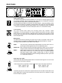
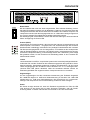
FRONT PANEL
Mains Switch
Use the mains switch to switch the unit’s power on. A soft-start function prevents inrush
current peaks on the mains, additionally preventing the mains line protection switch from
activating during the amp’s power-on operation. Loudspeaker outputs are activated via
relay switching with a delay of approx. 2 seconds, which effectively eliminates eventual
power-on noise.
During this delay period, the Protect LED lights to conrm correct operation of the
protection circuitry.
Protect (PROT)
A lit Protect LED indicates that one of the integrated protections against thermal overload,
short-circuit … has been activated. The audio channels’ protection circuits operate in-
dependent from each other. At the occurrence of failure or overload conditions the
affected power amp channel is separated from the load connected via output relay,
preventing the connected loudspeaker systems and the power amplier itself from
being damaged. Whatever caused the fault – e.g. a short-circuited speaker cable – needs
to be remedied. In case of thermal overload you have to wait until the power amplier
automatically returns to normal operation.
Limiter
The Limit indicator lights as soon as the integrated dynamic limiter is being activated
and the power amp is driven at the clipping limit or generally at its maximum capacity.
Short-term blinking is not a problem, because the internal limiter trims input levels of up
to +21dBu down to a THD+N of approximately 1%. If, on the other hand, this LED lights
constantly, reducing the volume is strongly recommended to prevent the connected
loudspeaker systems from being damaged by probable overload.
Level Indication
The level indicators signify the power amplier’s current modulation. The -30dB LED
starts lighting at approx. 30dB below full modulation while the -10dB LED lights at
approx. 10dB below full modulation. Shorted speaker cables or the activation of a
protection circuit causes these indicators to go out.
Power
The Power indicator lights when switching the power amplier on. If the power on LED
does not light please check to make sure the unit is plugged in or that the primary
fuse is not blown. If the fuse is blown please contact an authorized service center.
5

REAR PANEL
Audio Signal Inputs
The electronically balanced inputs facilitate the connection of external signal sources
(e.g. mixing consoles). When screwed to the power amp, the screwlock connectors
provided with the unit prevent accidental disconnection.
Choosing balanced cables (2 conductors for audio signals + separate shielding mesh)
for LF-signal connection is generally recommended, even when the connected signal
source does not provide balanced output signals. This is possible by jointly connecting
“–” conductor and shield on the source side (also refer to “LF-Connection Cords).
Level Controls
The Level Controls allow setting the according power amp channel’s overall
amplication. To prevent distortion in mixing consoles connected to the amp, setting
these controls to a value between -6dB and 0dB is generally recommended. A scale
provides direct indication of the varying additional control attenuation applied to the xed
internal amplication.
Mode Switch
The Mode Switch allows selecting the power amp’s mode of operation. With the four-
channel model it is possible to independently select channels A and B or C and D.
The single-channel model comes without mode switch.
DUAL: The power amp channels work independently from each other, each re-
producing the audio signals fed to the corresponding input.
PARALLEL: Both channels reproduce the audio signal fed to input A (or C). However,
using the level controls allows individually setting the channel volumes.
BDGD: Audio signals need to be fed to channel A (or C) when in Bridged Mode.
Power amps A and B (or C and D) now work in push-pull operation
delivering doubled output voltage. Please keep in mind to correctly
connect the loudspeaker systems for Bridged Mode operation. (also refer
to “Loudspeaker Outputs”)
High Pass Filter (HPF)
The Hi-Pass lter allows effective attenuation of low bass audio signals. You can choose
from three cut-off frequency settings:
Power Amps with low impedance outputs Power Amps with output transformer
300Hz, 12dB/Oct., BW 300Hz, 12dB/Oct., BW
50Hz, 12dB/Oct., BW 70Hz, 12dB/Oct., BW
OFF (no Hi-Pass lter) 50Hz, 18dB/Oct., BW
As a basic principle, all models with output transformer have a 50Hz Hi-Pass lter in the
audio signal path to protect the transformer from being driven into saturation by high
level low-frequency signals.
6

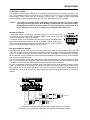
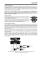
100V
25W
100V
25W
16 x 25W
100V
6W
100V
6W
66 x 6W
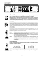
PA2450L & PA4150L
Loudspeaker systems connected to channels A and B (or C and D) have to be
connected according to the polarity indicated. Please, make sure to mind the
minimal impedance of 4 ohms per channel.
For bridged operation, the load has to be connected according to the BRIDGED-
label and the Mode switch needs to be set to “Bridged”. Please, make sure to
keep in mind that in Bridged Mode the minimal impedance is 8 ohms and that
the input audio signal has to be fed to channel A (or C).
REAR PANEL
Loudspeaker Outputs
The speaker output jacks are suitable for connecting speaker cables with a maximum diameter of 2.5
mm
2
. The provided screwlock connectors can be screwed to the power amp to prevent inadvertent
disconnection. Power amps offer low impedance outputs and / or oating outputs (ISOLATED
OUTPUTS) with nominal voltages of 50V, 70V and 100V, depending on the amp model.
Caution: The symbol of a FLASH at the loudspeaker connectors indicates that these outputs
may carry high voltages which, when getting in contact with, can cause serious harm.
Establishing connections at these outputs is only permissible for persons who have
been instructed on how to do so. Otherwise use prefabricated cables only.
PA1250T, PA2250T & PA2400T
Integrated audio output transformers convert the power amp’s nominal output voltage to 50V, 70V and
100V. The amplier models PA2250T and PA2400T present all voltages simultaneously at the oating
outputs so that the power amp channels can be used in any combination of possible output voltages.
Mixed operation of low-impedance speaker systems and oating loudspeaker lines on a single power
amp channel is possible as well.
The use of loudspeaker systems with 100V or 70V matching transformers to reduce the effects of cable
loss is recommended when the distance between power amp and speaker systems exceeds 165 feet.
In addition, this also facilitates distributing the output power among loudspeakers.
As many loudspeaker systems as possible can be connected, as long as the speaker network’s overall
power consumption does not exceed the power amp’s rated output power while at the same time not
falling below the nominal load impedance of the power amp outputs. Please refer to specications in
the appendix for individual values of the rated output power and nominal load impedance of power amp
outputs.
Conguration example: PA2400T with 100V speaker systems connected.
Maximum working loads with 25W/100V and 6W/100V loudspeaker systems.
7

REAR PANEL
Mains Fuse
Under normal circumstance, the mains fuse blows only in the event of failure. When
replacing the fuse, make sure to use a fuse of the same type with identical amperage,
voltage and blow characteristics. If the mains fuse blows repeatedly, please contact an
authorized service centre.
Mains Socket
Please, make sure to check whether the voltage selector is set to the correct mains
voltage that matches the local mains supply at the installation site. An appropriate mains
cord is included in the package.
Caution: This appliance has no user serviceable parts inside. Leave servicing to
a qualied professional.
Voltage Selector
Sliding selector switch for switching between mains voltages 115V - 230V. Prior to
switching the mains voltage, make sure to replace the mains fuse with an appropriate
model. Please refer to the label on the rear of the enclosure indicating the correct values
for different mains voltages.
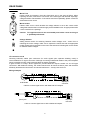
LF-connection cords
Choosing balanced cables (two conductors for audio signals plus separate shielding mesh) is
recommended for LF-signal connection. Although connecting unbalanced cables to the power amplier
inputs is possible as well, using balanced cables is always preferable.
A great number of today’s audio appliances provide balanced outputs carried out via XLR-type
connectors. With balanced cabling, the shield interconnects all metal enclosure parts and therefore
efciently eliminates the introduction of external interference – mostly noise and hum.
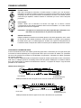
Wiring examples
8
XLR-female
amp input
connector
amp input
connector
phone jack
Cable to connect signal source with balanced XLR outputs.
Cable to connect signal source with unbalanced outputs.

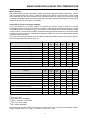
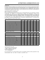
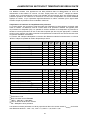
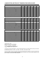
MAINS OPERATION & RESULTING TEMPERATURE
Mains Operation
The following tables provide a useful aid in determining power supply and cabling requirements. Column
“1/8 max. output power into 4 ohms
(2)
” states the values to be used for normal operation. These results
were measured with the power amplier being operated at maximum output and a Pink Noise signal
according to EN60065 applied at the input, which approximately represents the strain of an audio signal
driving the power amp at maximum modulation.
Temperatures inside of the power amplier
The power drawn from the mains network is converted into acoustic output to feed the connected
loudspeaker systems plus heat. The difference between drawn power and dispensed power is referred
to as leakage power or dissipation (P
D
). The amount of heat resulting from power dissipation might
remain inside of a rack-shelf and needs to be diverted using appropriate measures. The following table
is meant as auxiliary means for calculating temperatures inside of a rack-shelf system/cabinet and the
ventilation efforts necessary.
The column “P
D
” lists the leakage power in relation to different operational states. The column “BTU/hr”
shows the dispensed heat amount per hour.
PA2450L U
mains
[V]
I
mains
[A]
P
mains
[W]
P
out
[W]
P
D
[W]
BTU/
hr
(3)
idle 230 0,2 28 0 28 96
Max. output power into 8ohms
(1)
230 5,4 923 2x300 323 1102
Max. output power into 4ohms
(1)
230 8,8 1605 2x480 645 2201
1/3 max. output power into 4ohms
(1)
230 5,6 953 2x160 633 2160
1/8 max. output power into 4ohms
(1)
230 3,7 598 2x60 478 1631
1/8 max. output power into 4ohms
(2)
230 3,2 530 2x60 410 1399
1/8 max. output power into 4ohms
(2)
(4)
253 3,6 629 2x73 484 1651
Normal Mode (-10dB) into 4ohms
(1)
230 3,2 550 2x48 454 1549
Rated output power (0dB, rated) into 4ohms
(1)
230 8,1 1482 2x450 582 1986
Alert-Mode (-3dB) into 4ohms
(1)
230 6,1 1065 2x225 615 2098
PA4150L U
mains
[V]
I
mains
[A]
P
mains
[W]
P
out
[W]
P
D
[W]
BTU/
hr
(3)
idle 230 0,4 54,7 0 55 187
Max. output power into 8ohms
(1)
230 3,9 653 4x100 253 863
Max. output power into 4ohms
(1)
230 6,3 1126 4x160 486 1658
1/3 max. output power into 4ohms
(1)
230 4,0 665 4x53 452 1541
1/8 max. output power into 4ohms
(1)
230 2,7 428 4x20 348 1187
1/8 max. output power into 4ohms
(2)
230 2,4 385 4x20 305 1041
1/8 max. output power into 4ohms
(2)
(4)
253 2,6 450 4x24 353 1205
Normal Mode (-10dB) into 4ohms
(1)
230 2,4 385 4x16 321 1095
Rated output power (0dB, rated) into 4ohms
(1)
230 6,1 1080 4x150 490 1638
Alert-Mode (-3dB) into 4ohms
(1)
230 4,6 790 4x75 490 1672
(1)
Sine wave 1kHz
(2)
Pink noise acc. to EN60065
(3)
1BTU = 1055.06J = 1055.06Ws
(4)
10% mains over voltage
(5)
P
D
= Power dissipation
The following factors allow direct proportional calculation of the mains current (I
mains)
for different mains
supply voltages: 100V = 2,3; 120V = 1,9; 220V = 1,05; 240V = 0,96
9

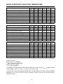
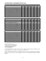
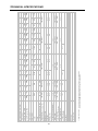
MAINS OPERATION & RESULTING TEMPERATURE
PA2400T - 100V output U
mains
[V]
I
mains
[A]
P
mains
[W]
P
out
[W]
P
D
[W]
BTU/
hr
(3)
idle 230 0,3 44,3 0 44 151
Max. output power into 25ohms
(1)
230 8,9 1643 2x430 783 2672
1/3 max. output power into 25ohms
(1)
230 5,5 952 2x143 665 2270
1/8 max. output power into 25ohms
(1)
230 3,7 602 2x54 495 1687
1/8 max. output power into 25ohms
(2)
230 3,3 545 2x54 438 1493
1/8 max. output power into 25ohms
(2)
(4)
253 3,7 646 2x65 516 1760
Normal-Mode (-10dB) into 25ohms
(1)
230 3,3 540 2x43 454 1549
Rated output power (0dB, rated) into 25ohms
(1)
230 8,5 1550 2x400 750 2559
Alert-Mode (-3dB) into 25ohms
(1)
230 6,3 1119 2x200 719 2453
PA2250T - 100V output U
mains
[V]
I
mains
[A]
P
mains
[W]
P
out
[W]
P
D
[W]
BTU/
hr
(3)
idle 230 0,2 31,6 0 32 108
Max. output power into 40ohms
(1)
230 5,5 960 2x270 420 1433
1/3 max. output power into 40ohms
(1)
230 3,5 571 2x90 391 1334
1/8 max. output power into 40ohms
(1)
230 2,3 365 2x34 298 1015
1/8 max. output power into 40ohms
(2)
230 2,1 330 2x34 263 896
1/8 max. output power into 40ohms
(2)
(4)
253 2,3 385 2x41 303 1035
Normal-Mode (-10dB) into 40ohms
(1)
230 2,1 328 2x27 274 935
Rated output power (0dB, rated) into 40ohms
(1)
230 5,4 929 2x250 429 1464
Alert-Mode (-3dB) into 40ohms
(1)
230 4,0 668 2x125 418 1426
PA1250T - 100V output U
mains
[V]
I
mains
[A]
P
mains
[W]
P
out
[W]
P
D
[W]
BTU/
hr
(3)
idle 230 0,2 21,7 0 22 74
Max. output power into 40ohms
(1)
230 2,8 487 1x270 217 740
1/3 max. output power into 40ohms
(1)
230 1,8 289 1x90 199 679
1/8 max. output power into 40ohms
(1)
230 1,2 182 1x34 148 506
1/8 max. output power into 40ohms
(2)
230 1,1 170 1x34 136 465
1/8 max. output power into 40ohms
(2)
(4)
253 1,2 197 1x41 156 533
Normal-Mode (-10dB) into 40ohms
(1)
230 1,1 164 1x27 137 467
Rated output power (0dB, rated) into 40ohms
(1)
230 2,7 471 1x250 221 754
Alert-Mode (-3dB) into 40ohms
(1)
230 2,0 339 1x125 214 730
(1)
Sine wave 1kHz
(2)
Pink noise acc. to EN60065
(3)
1BTU = 1055.06J = 1055.06Ws
(4)
10% mains over voltage
(5)
P
D
= Power dissipation
The following factors allow direct proportional calculation of the mains current (I
mains)
for different mains
supply voltages: 100V = 2,3; 120V = 1,9; 220V = 1,05; 240V = 0,96
For power amp models with integrated transformers, the listed values for the 100V outputs are equally
applicable for the 70V, 50V and for the low-impedance outputs as long as the connected load is
equivalent as well.
10
Page is loading ...
Page is loading ...
Page is loading ...
Page is loading ...
Page is loading ...
Page is loading ...
Page is loading ...
Page is loading ...
Page is loading ...
Page is loading ...
Page is loading ...
Page is loading ...
Page is loading ...
Page is loading ...
Page is loading ...
Page is loading ...
Page is loading ...
Page is loading ...
Page is loading ...

ALIMENTATION SECTEUR ET TEMPÉRATURE RÉSULTANTE
30
PA2400T - 100V output U
mains
[V]
I
mains
[A]
P
mains
[W]
P
out
[W]
P
D
[W]
BTU/
hr
(3)
idle 230 0,3 44,3 0 44 151
Max. output power into 25ohms
(1)
230 8,9 1643 2x430 783 2672
1/3 max. output power into 25ohms
(1)
230 5,5 952 2x143 665 2270
1/8 max. output power into 25ohms
(1)
230 3,7 602 2x54 495 1687
1/8 max. output power into 25ohms
(2)
230 3,3 545 2x54 438 1493
1/8 max. output power into 25ohms
(2)
(4)
253 3,7 646 2x65 516 1760
Normal-Mode (-10dB) into 25ohms
(1)
230 3,3 540 2x43 454 1549
Rated output power (0dB, rated) into 25ohms
(1)
230 8,5 1550 2x400 750 2559
Alert-Mode (-3dB) into 25ohms
(1)
230 6,3 1119 2x200 719 2453
PA2250T - 100V output U
mains
[V]
I
mains
[A]
P
mains
[W]
P
out
[W]
P
D
[W]
BTU/
hr
(3)
idle 230 0,2 31,6 0 32 108
Max. output power into 40ohms
(1)
230 5,5 960 2x270 420 1433
1/3 max. output power into 40ohms
(1)
230 3,5 571 2x90 391 1334
1/8 max. output power into 40ohms
(1)
230 2,3 365 2x34 298 1015
1/8 max. output power into 40ohms
(2)
230 2,1 330 2x34 263 896
1/8 max. output power into 40ohms
(2)
(4)
253 2,3 385 2x41 303 1035
Normal-Mode (-10dB) into 40ohms
(1)
230 2,1 328 2x27 274 935
Rated output power (0dB, rated) into 40ohms
(1)
230 5,4 929 2x250 429 1464
Alert-Mode (-3dB) into 40ohms
(1)
230 4,0 668 2x125 418 1426
PA1250T - 100V output U
mains
[V]
I
mains
[A]
P
mains
[W]
P
out
[W]
P
D
[W]
BTU/
hr
(3)
idle 230 0,2 21,7 0 22 74
Max. output power into 40ohms
(1)
230 2,8 487 1x270 217 740
1/3 max. output power into 40ohms
(1)
230 1,8 289 1x90 199 679
1/8 max. output power into 40ohms
(1)
230 1,2 182 1x34 148 506
1/8 max. output power into 40ohms
(2)
230 1,1 170 1x34 136 465
1/8 max. output power into 40ohms
(2)
(4)
253 1,2 197 1x41 156 533
Normal-Mode (-10dB) into 40ohms
(1)
230 1,1 164 1x27 137 467
Rated output power (0dB, rated) into 40ohms
(1)
230 2,7 471 1x250 221 754
Alert-Mode (-3dB) into 40ohms
(1)
230 2,0 339 1x125 214 730
(1)
Onde sinus 1 kHz
(2)
Bruit rose selon norme EN60065
(3)
1BTU = 1055.06J = 1055.06Ws
(4)
10% au-dessus de la tension secteur
(5)
P
D
= Dissipation de la puissance
Les facteurs suivants permettent un calcul proportionnel direct du courant secteur (I
mains)
en fonction
des différentes tensions : 100V = 2,3; 120V = 1,9; 220V = 1,05; 240V = 0,96
Pour les modèles d’ampli de puissance équipés de transformateurs intégrés, les valeurs mentionnées
pour les sorties en 100V sont également applicables aux sorties en 70V, 50V et basse impédance, tant
que la charge connectée est aussi équivalente.
Page is loading ...
Page is loading ...

32
33
BLOCK DIAGRAM PA2450L / PA4150L CH. A/B

34
35
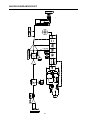
BLOCK DIAGRAM PA4150L CH. C/D

34
35
BLOCK DIAGRAM PA2400T / PA2250T

36
37
BLOCK DIAGRAM PA1250T

36
37
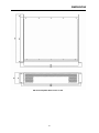
DIMENSIONS
PA series amplier dimensions in mm.
Page is loading ...
Page is loading ...

40
USA Telex Communications Inc., 12000 Portland Ave. South, Burnville, MN 55337, Phone: +1 952-884-4051, FAX: +1 952-884-0043
Germany EVI AUDIO, Hirschberger Ring 45, D 94315, Straubing, Germany Phone: 49 9421-706 0, FAX: 49 9421-706 265
Subject to change without prior notice. Printed in Germany 10/08/2006 / 361 122
www.electro-voice.de
-
 1
1
-
 2
2
-
 3
3
-
 4
4
-
 5
5
-
 6
6
-
 7
7
-
 8
8
-
 9
9
-
 10
10
-
 11
11
-
 12
12
-
 13
13
-
 14
14
-
 15
15
-
 16
16
-
 17
17
-
 18
18
-
 19
19
-
 20
20
-
 21
21
-
 22
22
-
 23
23
-
 24
24
-
 25
25
-
 26
26
-
 27
27
-
 28
28
-
 29
29
-
 30
30
-
 31
31
-
 32
32
-
 33
33
-
 34
34
-
 35
35
-
 36
36
-
 37
37
-
 38
38
-
 39
39
-
 40
40


Electro-Voice PA4150L User manual
- Category
- Audio amplifiers
- Type
- User manual
Ask a question and I''ll find the answer in the document
Finding information in a document is now easier with AI
in other languages
- français: Electro-Voice PA4150L Manuel utilisateur
- Deutsch: Electro-Voice PA4150L Benutzerhandbuch
Related papers
-
Electro-Voice CP-Series Power Amps CP1800 Owner's manual
-
Electro-Voice CP3000S User manual
-
-
-
-
-
-
-
-
Other documents
-
DYNACORD LX 2200 Owner's manual
-
-
-
-
DYNACORD LX 2200 Owner's manual
-
-
LY International Electronics PB-3002/PB-4002/PB-5002 Owner's manual
-
-
-
BOUYER AZ-1231 Datasheet