Page is loading ...

ceiling series
Manual de Usuario / User’s Manual
Antes de utilizar el equipo, lea la sección
“Precauciones de seguridad” de este manual.
Conserve este manual para futuras consultas.
Before operating the device, please read the
“Safety precautions” section of this manual.
Retainthismanualforfuturereference.

Ceiling SeriesCeiling Series
Precauciones de Seguridad
Safety Precautions
Precauciones de Seguridad
Safety
Precautions
Altavoces de techo / Ceiling loudspeakersAltavoces de techo / Ceiling loudspeakers
El signo de exclamación dentro de un triángulo indica la existencia
de importantes instrucciones de operación y mantenimiento en la
documentaciónqueacompañaalproducto.
Conserveyleatodasestasinstrucciones.
Sigalasadvertencias.
The exclamation point insidean equilateral triangle isintend to alert
the users to the presence of important operating and maintenance
(servicing)instructionsintheliteratureaccompanyingtheproduct.
Heedallwarnings.Followallinstructions.
Keeptheseinstructions.
Limpieconunpañoseco.Nouselimpiadorescondisolventes.
Las especificaciones se encuentran en la etiqueta de la parte
posteriordelproducto.
Thespecificationscanbefoundontherearlabeloftheproduct.
Cleanonlywithadrycloth.Donotuseanysolventbasedcleaners.
No existen partes ajustables por el usuario en el interior de este
equipo. Cualquier operación de mantenimiento o reparación debe
ser realizada por personal cualificado. Es necesario el servicio
técnico cuando el aparato se haya dañado de alguna forma, tal
como que haya caído líquido o algún objeto en el interior del
aparato, haya sido expuesto a lluvia o humedad, no funcione
correctamenteohayarecibidoungolpe.
No user serviceable parts inside. Refer all servicing to qualified
service personnel. Servicing is required when the apparatus has
been damaged in any way, such as power-supply cord or plug is
damaged, liquid has been spilled or objects have fallen into the
apparatus, the apparatus has been exposed to rain or moisture,
doesnotoperatenormallyorhasbeendropped.
Equipo diseñado para funcionar entre 15ºC y 35ºC con una
humedadrelativamáximadel75%.
Working temperature ranges from 15ºC to 35ºC with a relative
humidityof75%.
Noexpongaesteequipoalalluviaohumedad. EquipoIP-20. Donotexposethisdevicetorainormoisture.IP-20equipment.
No emplace altavoces en proximidad a equipossensiblesacampos
magnéticos, tales como monitores de televisión o material
magnéticodealmacenamientodedatos.
Do not place loudspeakers in proximity to devices sensitive to
magnetic fields such as television monitors or data storage
magneticmaterial.
Estos equipos están diseñados para instalarse en el techo, de forma
queelaccesoaellosquedelimitadoapersonalcualificado.
D.A.S. Audio no se responsabilizará de usos no recomendados de
este producto, ya sea la no utilización de los sistemas de fijación
suministrados, o la sujeción del altavoz a superficies que no tengan
resistenciaalatracción.
These systems are designed to be installed in the ceiling tiles, so
that access to them is limited to qualified personnel.
D.A.S. Audio is not responsible for use other than the
recommended. Use the only ceiling loudspeakers on ceiling tiles
that will provide sufficient support. Contact a licensed installer if
there is any doubt.
Véase el manual de instrucciones para la conexión e instalación. Refer to instructions manual for connection and installation.
Si el equipo tiene transformador de línea se indica en su etiqueta
posteriorconuna‘T’ final.
The device with line transformer included are marked on the rear
labelwitha‘T’.
Manual del Usuario / /Ceiling Loudspeakers User’s Manual

Todos nuestros productos están garantizados por un periodo de 24
meses desde la fecha de compra.
Las garantías sólo serán válidas si son por un defecto de
fabricación y en ningún caso por un uso incorrecto del producto.
Las reparaciones en garantía pueden ser realizadas,
exclusivamente, por el fabricante o el servicio de asistencia técnica
autorizado.
Otros cargos como portes y seguros, son a cargo del comprador
en todos los casos.
Para solicitar reparación en garantía es imprescindible que el
producto no haya sido previamente manipulado e incluir una
fotocopia de la factura de compra.
GARANTÍA
All D.A.S. products are warrantied against any manufacturing defect
for a period of 2 years from date of purchase.
The warranty excludes damage from incorrect use of the product.
All warranty repairs must be exclusively undertaken by the factory
or any of its authorised service centers.
To claim a warranty repair, do not open or intend to repair the
product.
Retur n the damaged unit, at shippers risk and freight prepaid, to
the nearest service center with a copy of the purchase invoice.
WARRANTY
Manual del Usuario / /Ceiling Loudspeakers User’s Manual

DECLARACIÓN DE CONFORMIDAD
DECLARATION OF CONFORMITY
D.A.S. AUDIO, S.A.
C/ Islas Baleares, 24 - 46988 - Pol. Fuente del Jarro - Valencia. España (Spain).
Declara que la serie Ceiling Loudspeakers:
Declares as it’s sole responsibility that series:Ceiling Loudspeakers
Cumple con los objetivos esenciales de las Directivas:
Abide by essential objectives relating Directives:
l
l
l
l
Directiva de Baja Tensión (Low Voltage Directive) 2006/95/CE
Directiva de Compatibilidad Electromagnética (EMC) 2004/108/CE
Directiva RoHS 2002/95/CE
Directiva RAEE (WEEE) 2002/96/CE
Y es conforme a las siguientes Normas Armonizadas Europeas:
In accordance with Harmonized European Norms:
l
l
l
EN 60065:2002 Audio, video and similar electronic apparatus. Safety
requirements.
EN 55103-1:1996 Electromagnetic compatibility. Product family standard for
audio, video, audio-visual and entertainment lighting control
apparatus for professional use. Part 1:Emission.
EN 55103-2:1996 Electromagnetic compatibility. Product family standard for
audio, video, audio-visual and entertainment lighting control
apparatus for professional use. Part 2:Immunity.
Manual del Usuario / /Ceiling Loudspeakers User’s Manual

Manual del Usuario / /Ceiling Loudspeakers User’s Manual

ÍNDICE
INTRODUCCIÓN 3
Generalidades
Características
Descripción
INSTALACIÓN 4
Consideraciones previas.Tipos de instalación
Instalación
AMPLIFICADORES DAS A EMPLEAR 7
MANTENIMIENTO. PRECAUCIONES 7
Manual del Usuario / /Ceiling Loudspeakers User’s Manual

Manual del Usuario / /Ceiling Loudspeakers User’s Manual

Manual del Usuario / /Ceiling Loudspeakers User’s Manual

CONTENTS
INTRODUCTION 11
General
Features
Description
INSTALLATION 12
Preliminary considerations. Types of installation
Installation
DAS AMPLIFIERS TO BE USED 15
MAINTENANCE. USE 15
Manual del Usuario / /Ceiling Loudspeakers User’s Manual

Manual del Usuario / /Ceiling Loudspeakers User’s Manual

11
1. INTRODUCTION
1.1 General
Thank you for purchasing D.A.S. products. This manual
contains the required information to make the best use of the
system you have purchased. Please take the time to read it.
1.2 Features
• The materials and design uses for these units represent
advanced sound reinforcement technology that delivers
outstanding audio performance from compact and easy-
to-use products. Sound field coverage is wide with
efficient mid and high frequency reproduction for greater
intelligibility.
• High induction magnetic circuits result in reduced
distortion and listening fatigue for spoken voice and
music reproduction.
• Polypropylene cones avoid age deterioration when
exposed to heat and air humidity.
• The series comprises seven models: CL-5, CL-6, CL-8,
CL-5T, CL-6T, CL-8T and CL-6TB.
• Technical specs are shown below for the basic models:
MODEL Nominal
Impedance
(ohm)
On axis
sensitivity
1W/1m
Average
(RMS) Power
Handling
(W)
Frequency
Range
Weight
(g)
F
S
(Hz)
CL-5 8 89dB SPL 20 70Hz-15kHz 725 68
CL-6 8 90dB SPL 40 60Hz-20kHz 1190 53
CL-8 8 90dB SPL 60 50Hz-20kHz 1575 48
MODEL On axis
sensitivity
1W/1m
Average (RMS)
Power Handling
Frequency
Range
Line voltage
(V)
3-6-X W 100CL-5T 89dB SPL
1.5-3-6 W
70Hz-20KHz
70.7
CL-6T 90dB SPL 5-10-15 W
2.5-5-7.5 W
60Hz-20kHz 100
70.7
CL-8T 90dB SPL 10-20-30 W
5-10-15 W
50Hz-20kHz 100
70.7
CL-6TB 90dB SPL 5-10-15 W
2.5-5-7.5 W
70Hz-20KHz 100
70.7
Position marked with an “X” should not be utilised.
• All models feature a removable protective grille with a
DAS logo, which allows access to the front of the
loudspeakers. For removal, a pointy object needs to be
introduced on a grille hole. For further detail, consult
section 3.2 of this manual.
WARNING: BE CAREFUL NOT TO DAMAGE THE CONE WITH
THE POINTY OBJECT WHEN REMOVING THE GRILLE
• Connection terminals are spring-loaded and colour coded:
red for positive, black for negative. Transformer models
have 4 terminals, a common one plus three other ones
that correspond to each of the three possible selected
input power levels. Check the back label for the
corresponding power for different line voltages. Do not
use the 6W terminal for a 100V line.
• The label on the speaker’s back plate contains the main
product specifications and standard compliances.
• All models comprise three main elements: the plastic
support, the speaker and the grille. The back of the
support houses four small turrets for the screws that fix
the speaker chassis, plus other four larger turrets. The
latter house the tabs that fix the speaker assembly to the
ceiling tile assembly when rotating the turrets’ screws.
• Thus, all models have eight screws, 4 for fixing the
speaker to its plastic support, and four that operate the
mounting tabs that fix the assembly to the ceiling.
• All screws are accessed from the back, i.e. the front grille
must be removed for screwing/unscrewing.
• All models are shipped with a tile cut out template. If
painting of the plastic ring is needed, a round paper piece
is also shipped to cover the rest of the speaker when
painting.
Manual del Usuario / /Ceiling Loudspeakers User’s Manual

12
The exploded view below identifies the different elements to
ease handling and installation:
Fig. 1 –CL-5, front view
Fig. 2 –CL-5, back view
2. INSTALLATION
2.1 Preliminary considerations. Types of installation
For complete installation, we n
eed to take the time to plan
ahead the cutting out tile holes and the cabling of the units.
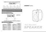
Conventional amplifiers can be
used to power the DAS ceiling
speakers. With them, two types of wiring configurations are
possible.
A parallel configuration allows the use of two speakers per
channel for a 4 ohm load:
Fig. 3 – parallel connection
1.3 Description
The three basic models of the series can be seen below:
Series-parallel connection. Two loads are wired per channel,
each load consisting of four uni
ts connected in series-parallel.
A total of 8 speakers per channe
l can be installed this way:
Fig. 4 - series-parallel connection
Manual del Usuario / /Ceiling Loudspeakers User’s Manual

13
2.2 Installation
The different installation steps are described. Before this can
take place, the installation should be wired, leaving all of the
ceiling wiring in place and ready for connection.
Step 1 – Remove the speaker grille: The grille must be
removed for access to the mounting screws. Insert a pointy
object and introduce it in a grille hole close to the edge. You’ll
remove the grille with ease if using two pointy objects on
opposite ends.
WARNING: BE CAREFUL NOT TO DAMAGE THE CONE WITH
THE POINTY OBJECT WHEN REMOVING THE GRILLE
Step 2 – Ceiling tile cut out: The following table lists the
inner and recommended cut out diameters for the different
models and the necessary depth in the ceiling structure to
install the speakers:
Table 1: inner and cut out diameters
Packaged with the speakers is a cardboard cut out template
for scribing the cut out hole onto your ceiling surface. The
inside circumference of the same template can be used to
cover the rest of the speaker when painting.
Therefore the cut out may be scribed using the template
provided or by drawing a circumference of the diameter in
table 1. Once the hole is cut, you may need to pull down the
cables so they are accessible for connection.
Fig. 6 – circular cut out, installation wiring
Step 3 – Terminal connection: the speakers terminals are
spring loaded. Watch the colour coding for polarity. For
connection to transformer models, you will need to select the
required input power and connect to the appropriate terminals
(see Fig. 7).
MODEL Depth INNER
DIAMETRE
CUT OUT
DIAMETRE
CL-5, CL-5T
CL-6, CL-6T
CL-8, CL-8T
CL-6TB 160mm 198mm (7.8 in) 202mm (7.9 in)
70mm 165 mm (6.6 in) 166 mm (6.65 in)
80mm 193 mm (7.7 in) 194 mm (7.76 in)
97mm 237 mm (9.5 in) 238 mm (9.52 in)
Similarly, if one does not wish to use a transformer model, the
number of units in series-parallel can be increased, as long as
4 or more ohms impedance is achieved, as follows.
Each amplifier will drive two load
s in parallel. Each will consist
of the parallel connection of as many loads as we want to
connect in series. Each of the la
tter loads consists of the units
to be series connected (see illustration).
Fig. 4.1 – Series-parallel connection of a large number of
speakers per channel
When working with a large number of units wired this way,
one should ensure that all
speakers get enough power.
Otherwise the user will tend to overload the amplifier, which
in turn may result in speaker failure.
Example: for the system on the illustration, assuming CL-6
(40W):
Each channel drives 18 units, for a total of 8x40=720W worth
of speaker power handling. Since amplifier channel should be
100-150% of the speakers’ power handling, 720 to 1000 W
should be used for amplifier power (at 4 ohm).
For very large installations, th
e (6W) line transformer model
CL-5T should be used.
Fig. 5 – Parallel connection of transformer units
WARNING: BEFORE INSTALLING THE SPEAKERS, MAKE
SURE THERE IS A MINIMUM CEILING VOID HEIGHT OF 100
MM (4”).
Manual del Usuario / /Ceiling Loudspeakers User’s Manual

14
Step 5 – Screwing and fixing: to fix the assembly to the
ceiling, the tabs have to be rotated and lowered. This is done
by tightening the corresponding screws clockwise. The first
quarter turn rotates the tab into position and out of the guide;
the rest tightens the tab down onto the back of the ceiling
surface. The process needs to be repeated for all four screws.
Fig. 9 – fixing the speaker to the ceiling
Fig. 10 – fixing system: when tightening the screw the
mounting tab comes down, pressing the plastic support
against the ceiling.
Step 6 – Replace the grille: once the speaker is fixed to the
ceiling, this is the only operation left.
Push the grille into place until fixed. You will need to use the
adhesives stripes provided.
Note: the grille shows some degree of resistance to be
removed. Fixing is by contact, so there is little clearance
between its inner diameter and the inner support, so that
some force needs to be applied when removing it.
Fig. 7 – CL-5T; input power selection terminals
Step 4 – Inserting the speaker: follow these steps:
• Hold the speaker in one hand, while you use the other
hand to connect the cable to the speaker.
• Push the assembly all the way into hole. The four
mounting tabs must be tangential to the ring, otherwise
they’ll be in the way.
Fig. 8 – terminal connection; speaker positioning
WARNING: ALWAYS HOLD THE SPEAKER BY THE PLASTIC
SUPPORT, AVOIDING DAMAGE TO THE TRANSDUCER
DIAPHRAGMS
Manual del Usuario / /Ceiling Loudspeakers User’s Manual

15
3. DAS AMPLIFIERS TO BE USED
For model CL-5T installations, some DAS Audio amplifiers
provide 70 and 100V outputs.
Model Line
(V)
Mode Power
(W)
E-12 50 Stereo 650
E-20 70 Stereo 960
E-12 100 Bridge 1220
To calculate the required amplifier power for a 70 or 100V line,
simply sum the input power selection of all speakers
connected to a given amplifier channel. Example: for a 70V
line with 40 units of CL-5T (with multi-tap transformer that
offers a selection of 1.5,3 and 6W) which are all set to 6W,
the total speaker power handling will be 40x6=240W. The
only requirement is that the total speaker power is below the
amplifier’s output power.
4. MAINTENANCE, USE
No maintenance is needed for the products in this manual if
they have been installed correctly and following the
instructions in this manual.
Some usage tips follow:
The best maintenance for a speaker is its correct use, i.e.,
within the design parameters. It is important not to utilise
amplifiers that are too large when compared to the speaker
power. In general, it is recommended that you use an amplifier
with an output that is 100% to 150% of the speaker's average
(RMS) power rating. That way we have headroom for the
dynamics of real music and vocal signals, and at the same
time deliver a cleaner signal to the speakers that will result in
a more reliable system. Avoid using too small an amplifier.
The clip light of your amplifiers should never be on
continuously. This will distort the signal and may damage the
speakers. In fact, severe clipping is an easy way to burn a
speaker’s voice coil. At most, the clip light could blink
occasionally. When clipped, signals sound distorted and
produce listening fatigue quickly.
Never use a total impedance load that is lower than the
lowest impedance that an amplifier will take. Virtually all
professional amplifiers will accept loads down to four ohms
safely in stereo mode. Many are rated for two ohm loads but
often will run into overheating protection when used this way,
particularly in high ambient temperature and high output
power applications. Never connect more speakers to an
amplifier's channel than it will take, i.e. do not load a channel
with total impedance that is lower than the minimum load
specified by the manufacturer.
Manual del Usuario / /Ceiling Loudspeakers User’s Manual

Manual del Usuario / /Ceiling Loudspeakers User’s Manual

UM_CL_01
www.dasaudio.com
D.A.S. AUDIO OF AMERICA, INC.
Sunset Palmetto Park
6816 NW 77th Court.
Miami, FL. 33166 - U.S.A.
TOLL FREE: 1-888DAS4USA
Tel. +1 305 436 0521
Fax +1 305 436 0528
D.A.S. AUDIO ASIA PTE. LTD.
25 Kaki Bukit Crescent #01-00/02-00
Kaki Bukit Techpark 1
Singapore 416256
Tel. +65 6742 0151
Fax +65 6742 0157
D.A.S. AUDIO, S.A.
C/. Islas Baleares, 24
Tel. 96 134 0525
Tel. Intl. +34 96 134 0860
Fax 96 134 0607
Fax Intl. +34 96 134 0607
46988 Fuente del Jarro
Valencia, SPAIN
/