Page is loading ...

ISTRUZIONI D’USO E DI INSTALLAZIONE
INSTALLATION AND USER’S MANUAL
INSTRUCTIONS D’UTILISATION ET D’INSTALLATION
INSTALLATIONS-UND GEBRAUCHSANLEITUNG
INSTRUCCIONES DE USO Y DE INSTALACION
INSTALLATIEVOORSCHRIFTEN
ATTUATORE PER CANCELLI SCORREVOLI A CREMAGLIERA
ACTUATOR FOR RACK SLIDING GATES
ACTIONNEUR POUR PORTAILS COULISSANTS A CREMAILLERE
ANTRIEB FÜR ZAHNSTANGEN-SCHIEBETORE
SERVOMOTOR PARA CANCELAS CORREDERAS DE CREMALLERA
ACTUATOR VOOR SCHUIFHEKKEN MET TANDHEUGEL
Attenzione! Leggere attentamente le “Avvertenze” all’interno! Caution! Read “Warnings” inside carefully! Attention! Veuillez lire attentivement les Avertissements qui se trouvent à l’intérieur!
Achtung! Bitte lesen Sie aufmerksam die „Hinweise“ im Inneren! ¡Atención¡ Leer atentamente las “Advertencias” en el interior! Let op! Lees de “Waarschuwingen” aan de binnenkant zorgvuldig!
ARES
ARES
D811692 00100_04 21-06-11
8
027908 360564

3x1mm
2
3x1.5mm
2
2x0.75mm
2
3x1.5mm
2
RG58
3x1.5mm
2
3x1.5mm
2
5x0,75mm
2
2x1.5mm
2
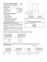
Predisposizione fissaggio motore, Preparation for motor mounting,
Aménagement fixation moteur, Vorbereitung Motorbefestigung,
Disposición fijación del motor, Voorbereiding bevestiging motor.
25mm + “X”
“X”= Cremagliera, Rack,
Crémaillère, Zahnstange,
Cremallera, Tandheugel
Montaggio motore, Mounting the motor, Montage moteur,
Montage Motor, Montaje del motor, Montage motor.
Montaggio accessori trasmissione, Mounting drive accessories,
Montage accessoires transmission, Montage Antriebszubehör,
Montaje de accesorios transmisión, Montage accessoires overbrenging.
Fissaggio staffe finecorsa (dx e sx), Fastening limit switch brackets (RH/LH),
Fixation étriers fin de course (drt et gch), Befestigung Bügel Anschläge (rechts und links),
Fijación abrazaderas final de carrera (der. e izq.),
Bevestiging stangen aanslag (rechts en links).
Y
Y
Collegamento morsettiera, Terminal board wiring,
Connexion plaque à bornes, Anschluss Klemmleiste,
Conexión tablero de bornes, Aansluiting aansluitkast.
> 10mm
> 25mm
A
C
E
B
D
F
D1
PREDISPOSIZIONE TUBI, TUBE ARRANGEMENT,
PRÉDISPOSITION DES TUYAUX, VORBEREITUNG DER LEITUNGEN,
DISPOSICIÓN DE TUBOS, VOORBEREIDING LEIDINGEN.
INSTALLAZIONE VELOCE-QUICK INSTALLATION-INSTALLATION RAPIDE
SCHNELLINSTALLATION-INSTALACIÓN RÁPIDA - SNELLE INSTALLATIE
2 - ARES
D811692 00100_04

ITALIANO ENGLISH
FRANÇAIS
DEUTSCH
ESPAÑOL
NEDERLANDS
JP3
24 12 1321
COM
PHOT
24V ~
Rx 1
Tx 1
1
2
3
4
5
1
2
Connection of 1 pair of non-tested photocells
Anschluss von einem Paar nicht überprüften Fotozellen
Conexión de 1 par fotocélulas no comprobadas
Aansluiting van 1 paar fotocellen anders dan “trusted device”
Connettore programmatore palmare,
Palmtop programmer connector,
Connecteur programmateur de poche,
Steckverbinder Palmtop-Programmierer,
Conector del programador de bolsillo,
Connector programmeerbare palmtop
Connettore scheda opzionale
Optional board connector
Connecteur carte facultative
Steckverbinder Zusatzkarte
Conector de la tarjeta opcional
Connector optionele kaart
G
H
1
JP9
13 12 14
SCA
II° CH
15
JP9
14 15
24 V~
VSAFE ~(+)
VSAFE ~(-)
24V ~(+)
0V(-)
25W max.
LOGICA test fotocellule OFF/ Photocell test LOGIC OFF
LOGIQUE essai photocellules Désactivée /
LOGIK Test Fotozellen OFF
LÓGICA prueba fotocélulas OFF / LOGICA test fotocellen OFF
ne
ngstasten
Display + programmeringstoetsen
Display + tasti programmazio
Display + programming keys
Display + Programmieru
Pantalla + botones programación
123456789101112131415161718192021222324252627
JP2
JP1
31 32 33 34
N
L
24V
~
230V
~
FAULT PHOT
COM
PED
COM
SWC
SWO
~ (+)
COM
START/CLOSE
STOP
PHOT
BAR
OPEN
FAULT BAR
M
NC
NC
NO
NO
NC
NC
NC
NO
NO
NO
24V
0V (-)
ANT
Grigio-Grey-Gris-Grau-Gris-Grijs
Grigio-Grey-Gris-Grau-Gris-Grijs
SCA/2°CH
Led presenza alimentazione
Power ON LED
Del de présence de tension
LED Stromversorgung vorhanden
Led presencia de alimentación
Led aanwezigheid voeding
1,6A T 230V
3,15A T 120V
F1
F2
3,15A T
ARES - 3
D811692 00100_04

x1
language
dir
ITA
fra
deu
eng
esp
lh
rh
AR
preset
e
hidden button
release O 01
re otes
sr
ac
sc
ind
end
ar: automatic operation,
residential
sr: semiautomatic operation,
residential
ac: automatic operation,
commercial
Sc: semiautomatic operation,
commercial
Ind:dead man operation
lh
rh
desidered button
: motor installed on the left
: motor installed on the right
autoset
. . . . . .
o o
AUTO OPEN
AUTO CLOSE
MIN 1 - MAX 3
Exit Menù
Conrm/Switch
on display
Scroll up
Scroll down
SIMPLIFIED MENU
PRESET DEFAULT
ar sr ac sc ind
PARAMETERS
Automatic
Closing Time
40 40 40 40 40 40
Slow-down speed 15 15 15 15 15 15
Opening motor torque 75 75 75 75 75 75
Closing motor torque 75 75 75 75 75 75
Speed during opening 99 99 99 99 99 99
Speed during closing 99 99 99 99 99 99
Partial opening 40 40 40 40 40 40
Zone 0 0 0 0 0 0
Slow-down distance 0 0 0 0 0 0
Opening deceleration space 10 10 10 10 10 10
Closing deceleration space 10 10 10 10 10 10
LOGIC
Automatic Closing Time OFF ON OFF ON OFF OFF
Block Pulses OFF OFF OFF ON ON OFF
Impulse lock TCA OFF OFF OFF OFF OFF OFF
3 step OFF ON OFF ON OFF OFF
Pre-alarm OFF OFF OFF ON ON OFF
Deadman OFF OFF OFF OFF OFF ON
Photocells
during opening
OFF ON ON ON
ON OFF
Photocell test OFF OFF OFF OFF OFF OFF
Safety edge testing OFF OFF OFF OFF OFF OFF
Master/Slave OFF OFF OFF OFF OFF OFF
Fixed code OFF OFF OFF OFF OFF OFF
Remote control
programming
ON ON ON ON ON ON
Gate open light or 2nd radio
channel
OFF OFF OFF OFF OFF OFF
START - CLOSE setting OFF OFF OFF OFF OFF OFF
Reversing motion - - - - - -
ICE OFF OFF OFF OFF OFF OFF
ARES - 5
D811692 00100_04

Connessione Seriale Mediante Scheda Scs1 , Serial Connection Via Scs1 Card, Connexion Série À Travers La Carte Scs1, Serielle Verbindung Mit Karte Scs1,
Conexión Serial Mediante Tarjeta Scs1, Seriële Verbinding Middels Kaart Scs1.
SCHEDA DI ESPANSIONE
EXPANSION BOARD
CARTE EXPANSION
ERWEITERUNGSKARTE
TARJETA DE EXPANSIÓN
UITBREIDINGSKAART
Programmeerbare Universele Palmtop
T
S
SCS1
TX1 (PHOT)
RX1 (PHOT) BAR2 BAR1
TX2 (PHOT)
RX2 (PHOT)
M2
SLAVE
M1
MASTER
zone=128
aster=ON
zone=128
aster=OFF
123456789101112131415161718192021222324252627
JP2
JP1
31 32 33 34
COM
NC
BAR2
COM
NC
SWC
NC
SWO
24 V
~
+
0 V(-)
0 V(-)
V Safe -
V Safe +
RXRXTXTX
123456789101112131415161718192021222324252627
JP2
JP1
31 32 33 34
COM
NC
SWC
NC
SWO
FAULT-PHOT
FAULT-BAR 2
FAULT-BAR 1
COM
NO
24 V
~
+
V Safe -
V Safe +
RXRXTXTX
ANT
24V
25W Max
24V
25W Max
SCA/2°CH
PED
COM
NO
NO
NC
NO
NC
NC
ST ART/CLOSE
STOP
PHOT
BAR1
OPEN
U
NO
SCS1
8888
UNIDA
SLAVE SLAVE MASTER
Connessione seriale per ante contrapposte, Serial connection for opposite leaves, Connexion série pour vantaux opposés, Serieller Anschluss für
einander entgegengesetzte Torflügel, Conexión serial para hojas contrapuestas, Seriële verbinding voor tegenovergestelde vleugels.
ARES - 11
D811692 00100_04

ACCESS TO MENUS Fig. 1
Closing
Opening
para . 1
para . 2
para . . . .
logic. 1logic
logic. 2
logic. . . .
add. start
hidden button
release ok 01
desired button
PRG.
erase 64
COD RX
1 A9C
OK
2 2FD
OK
0 1
OK
Add. 2ch
+/-
radio
ITA
FRA
DEU
ENG
esp
OK
OK
OK
OK
OK
-
+
-
+
-
+
-
+
language
PRG
default
ok 01
hidden button
release
desired button
v
Exit Menù
Conrm/Switch on display
Scroll up
Scroll down
x 2
-
+
-
+
OK OK
stat
vers
bft . . .
+/-
OK
0000
+/-
+/-
n. cycles
OK
00
n. Re otes
autoset
A
F
D
C
B
E
C
F
Fig.2
See PARAMETERS
MENU
See LOGIC
MENU
See RADIO
MENU
DIAGNOSTICS and WARNINGS
DIAGNOSTICS
CODE
DESCRIPTION NOTES
ped
pedestrian input activated
STRE
START input activated
stop
STOP input activated
phot
attivazione ingresso PHOT
bar
SAFETY EDGE input activated
bar2
SAFETY EDGE input activated on slave motor
(opposite leaves connection)
cls
CLOSE input activated
open
OPEN input activated
svo
opening limit switch input activated
svc
closing limit switch input activated
set
the board is standing by to perform a com-
plete opening-closing cycle uninterrupted by
intermediate stops in order to acquire the tor-
que required for movement.
WARNING! Obstacle detection function is
not active
Er01
photocell test error
check photocell connection and/or
logic settings
Er02
safety edge test error
check safety edge connection and/or
logic settings
Er05
safety edge test error on slave motor (opposite
leaves connection)
check safety edge connection and/or
parameter/logic settings
Er1x*
board hardware test error check connections to motor
er3x*
reverse due to obstacle check for obstacles in path
Er4x*
thermal cutout error Allow motor to cool
Er5x*
anomaly in communication w/ remote de-
vices
check Scs1 serial connections
ER61
running o battery --
ErFx*
limit switch error check limit switch connections
* X = 0,1,…,9,A,B,C,D,E,F
35.40
Set torque threshold
Maximum instantaneous motor torque
18 - ARES
D811692 00100_04

ENGLISH
INSTALLER WARNINGS
Anything that is not explicitly provided for in the installation ma-
nual is not allowed. The operator’s proper operation can only be
guaranteed if the information given is complied with. The Firm shall
not be answerable for damage caused by failure to comply with the
instructions featured herein.
While we will not alter the product’s essential features, the Firm re-
serves the right, at any time, to make those changes deemed oppor-
tune to improve the product from a technical, design or commercial
point of view, and will not be required to update this publication
accordingly.
WARNING! Important safety instructions. Carefully read and comply with
all the warnings and instructions that come with the product as incorrect
installation can cause injury to people and animals and damage to proper-
ty. The warnings and instructions give important information regarding
safety, installation, use and maintenance. Keep hold of instructions so that
you can attach them to the technical le and keep them handy for future
reference.
GENERAL SAFETY
This product has been designed and built solely for the purpose indicated herein.
Uses other than those indicated herein might cause damage to the product and
create a hazard.
- The units making up the machine and its installation must meet the requirements
of the following European Directives, where applicable: 2004/108/EC, 2006/95/
EC, 2006/42/EC, 89/106/EC, 99/05/EC and later amendments. For all countries
outside the EEC, it is advisable to comply with the standards mentioned, in
addition to any national standards in force, to achieve a good level of safety.
- The Manufacturer of this product (hereinafter referred to as the “Firm”) disclaims
all responsibility resulting from improper use or any use other than that for
which the product has been designed, as indicated herein, as well as for failure
to apply Good Practice in the construction of entry systems (doors, gates, etc.)
and for deformation that could occur during use.
- Installation must be carried out by qualied personnel (professional installer,
according to EN 12635), in compliance with Good Practice and current code.
- Before commencing installation, check the product for damage.
- Before installing the product, make all structural changes required to produce
safety gaps and to provide protection from or isolate all crushing, shearing and
dragging hazard areas and danger zones in general. Check that the existing
structure meets the necessary strength and stability requirements.
- The Firm is not responsible for failure to apply Good Practice in the construction
and maintenance of the doors, gates, etc. to be motorized, or for deformation
that might occur during use.
- Make sure the stated temperature range is compatible with the site in which the
automated system is due to be installed.
- Do not install this product in an explosive atmosphere: the presence of ammable
fumes or gas constitutes a serious safety hazard.
- Disconnect the electricity supply before performing any work on the system.
Also disconnect buer batteries, if any are connected.
- Before connecting the power supply, make sure the product’s ratings match the
mains ratings and that a suitable residual current circuit breaker and overcurrent
protection device have been installed upline from the electrical system. Have
the automated system’s mains power supply tted with a switch or omnipolar
thermal-magnetic circuit breaker with a contact separation of at least 3.0mm
and any other equipment required by code.
- Make sure that upline from the mains power supply there is a residual current
circuit breaker that trips at no more than 0.03A as well as any other equipment
required by code.
- Make sure the earth system has been installed correctly: earth all the metal parts
belonging to the entry system (doors, gates, etc.) and all parts of the system
featuring an earth terminal.
- Installation must be carried out using safety devices and controls that meet
standards EN 12978 and EN 12453.
- Impact forces can be reduced by using deformable edges.
- In the event impact forces exceed the values laid down by the relevant standards,
apply electro-sensitive or pressure-sensitive devices.
- Apply all safety devices (photocells, safety edges, etc.) required to keep the
area free of impact, crushing, dragging and shearing hazards. Bear in mind the
standards and directives in force, Good Practice criteria, intended use, the in-
stallation environment, the operating logic of the system and forces generated
by the automated system.
- Apply all signs required by current code to identify hazardous areas (residual
risks). All installations must be visibly identied in compliance with the provisions
of standard EN 13241-1.
- This product cannot be installed on leaves incorporating doors (unless the motor
can be activated only when the door is closed).
- If the automated system is installed at a height of less than 2.5 m or is accessible,
the electrical and mechanical parts must be suitably protected.
- Install any xed controls in a position where they will not cause a hazard, away
from moving parts. More specically, hold-to-run controls must be positioned
within direct sight of the part being controlled and, unless they are key operated,
must be installed at a height of at least 1.5 m and in a place where they cannot
be reached by the public.
- Apply at least one warning light (ashing light) in a visible position, and also
attach a Warning sign to the structure.
- Attach a label near the operating device, in a permanent fashion, with information
on how to operate the automated system’s manual release.
- Make sure that, during operation, mechanical risks are avoided or relevant protec-
tive measures taken and, more specically, that nothing can be banged, crushed,
caught or cut between the part being operated and surrounding parts.
- Once installation is complete, make sure the motor automation settings are
correct and that the safety and release systems are working properly.
- Only use original spare parts for any maintenance or repair work. The Firm di-
sclaims all responsibility for the correct operation and safety of the automated
system if parts from other manufacturers are used.
- Do not make any modications to the automated system’s components unless
explicitly authorized by the Firm.
- Instruct the system’s user on what residual risks may be encountered, on the
control systems that have been applied and on how to open the system manually
in an emergency. give the user guide to the end user.
- Dispose of packaging materials (plastic, cardboard, polystyrene, etc.) in accor-
dance with the provisions of the laws in force. Keep nylon bags and polystyrene
out of reach of children.
WIRING
WARNING! For connection to the mains power supply, use: a multicore cable
with a cross-sectional area of at least 5x1.5mm
2
or 4x1.5mm
2
when dealing
with three-phase power supplies or 3x1.5mm
2
for single-phase supplies (by
way of example, type H05 VV-F cable can be used with a cross-sectional area
of 4x1.5mm
2
). To connect auxiliary equipment, use wires with a cross-sectional
area of at least 0.5 mm
2
.
- Only use pushbuttons with a capacity of 10A-250V or more.
- Wires must be secured with additional fastening near the terminals (for example,
using cable clamps) in order to keep live parts well separated from safety extra
low voltage parts.
- During installation, the power cable must be stripped to allow the earth wire
to be connected to the relevant terminal, while leaving the live wires as short
as possible. The earth wire must be the last to be pulled taut in the event the
cable’s fastening device comes loose.
WARNING! safety extra low voltage wires must be kept physically separate from
low voltage wires.
Only qualied personnel (professional installer) should be allowed to access
live parts.
CHECKING THE AUTOMATED SYSTEM AND MAINTENANCE
Before the automated system is nally put into operation, and during maintenance
work, perform the following checks meticulously:
- Make sure all components are fastened securely.
- Check starting and stopping operations in the case of manual control.
- Check the logic for normal or personalized operation.
- For sliding gates only: check that the rack and pinion mesh correctly with 2 mm
of play; keep the track the gate slides on clean and free of debris at all times.
- Check that all safety devices (photocells, safety edges, etc.) are working properly
and that the anti-crush safety device is set correctly, making sure that the force
of impact measured at the points provided for by standard EN 12445 is lower
than the value laid down by standard EN 12453.
- Make sure that the emergency operation works, where this feature is provi-
ded.
- Check opening and closing operations with the control devices applied.
- Check that electrical connections and cabling are intact, making extra sure that
insulating sheaths and cable glands are undamaged.
- While performing maintenance, clean the photocells’ optics.
- When the automated system is out of service for any length of time, activate the
emergency release (see “EMERGENCY OPERATION” section) so that the operated
part is made idle, thus allowing the gate to be opened and closed manually.
SCRAPPING
Materials must be disposed of in accordance with the regulations in force. There
are no particular hazards or risks involved in scrapping the automated system. For
the purpose of recycling, it is best to separate dismantled parts into like materials
(electrical parts - copper - aluminium - plastic - etc.).
DISMANTLING
If the automated system is being dismantled in order to be reassembled at another
site, you are required to:
- Cut o the power and disconnect the whole electrical system.
- Remove the actuator from the base it is mounted on.
- Remove all the installation’s components.
- See to the replacement of any components that cannot be removed or happen
to be damaged.
AVVERTENZE PER L’INSTALLATORE D811766_03
ARES - 19
D811692 00100_04

INSTALLATION MANUAL
1) FOREWORD
The ARES actuator is highly versatile in terms of installation options due to the
extremely low position of the pinion, the actuator’s compact nature and the
height and depth adjustment features it oers. The adjustable electronic torque
limiter provides anti-crush safety. Manual emergency operation is extremely easy
to perform using just a knob.
Stopping at end of travel is controlled by electromechanical microswitches.
The built-in control panel controls the start relays and safety devices (photocells,
safety edge) each time before performing any operation.
2) TECHNICAL SPECIFICATIONS
MOTOR
Power supply single-phase 230V ±10%, 50Hz (*)
Power input
400 W (ARES 1500)
240 W (ARES 1000)
Pinion module
4mm (18 teeth) (ARES 1500/ARES 1000)
4mm (25 teeth) (ARES 1500V / ARES 1000 V)
Leaf speed
9 m/min (ARES 1500/ARES 1000)
12 m/min (ARES 1500V / ARES 1000V)
Max. leaf weight
1500 Kg (ARES 1500) 1000 Kg (ARES 1000)
750 Kg (ARES 1500V) 500 Kg (ARES 1000V)
Max. torque
35 Nm (ARES 1500)
30 Nm (ARES 1000)
Impact reaction Electronic torque limiter
Lubrication Lifetime greased
Manual operation Knob-operated mechanical release
Type of use intensive
Buffer batteries (optional
extras)
Two 12V 1.2Ah batteries
Environmental conditions from -15°C to +60°C
Protection rating IP24
Noise level <70dBA
Operator weight 7 kg
Dimensions See Fig. K
CONTROL UNIT
Accessories power supply 24V ~ (180 mA)
Fuses Fig. G
Built-in Rolling-Code radio-receiver
frequency 433.92MHz
Setting of parameters and
options
Universal handheld programmer/LCD display
N° of combinations 4 billion
Max. n° of remotes that can
be memorized
63
(*) Special supply voltages to order.
Usable transmitter versions:
All ROLLING CODE transmitters compatible with
3) TUBE ARRANGEMENT Fig.A
Install the electrical system referring to the standards in force for electrical
systems CEI 64-8, IEC 364, harmonization document HD 384 and other national
standards.
4) PREPARATION FOR MOTOR MOUNTING FIG.B
• Makeaholeinthegroundtoaccommodatetheconcretepad,withanchors
embedded in the base plate for fastening the gearbox assembly, keeping to
the distances featured in FIG.B.
• Tokeepthebase plate in the right position during installation, itmaybe
useful to weld two iron plates under the track to which the anchors can then
be welded (FIG.M).
5) MOUNTING THE MOTOR FIG.C
6) MOUNTING DRIVE ACCESSORIES FIG.D-D1
7) RACK CENTRING WITH RESPECT TO PINION FIG.N-O1-P
DANGER - Welding must be performed by a competent person issued
with the necessary personal protective equipment as prescribed by
the safety rules in force FIG.O.
8) FASTENING LIMIT SWITCH BRACKETS FIG.E
9) STOPS FIG.Q
DANGER - The gate must be tted with mechanical stops to halt its
travel both when opening and closing, thus preventing the gate from
coming o the top guide. Said stops must be fastened rmly to the ground,
a few centimetres beyond the electric stop point.
10) MANUAL RELEASE (See USER GUIDE -FIG.2-).
Warning Do not JERK the gate open and closed, instead push it GENTLY to
the end of its travel.
----------------------------------------------------------
11) TERMINAL BOARD WIRING Fig. F-G
Once suitable electric cables have been run through the raceways and the auto-
mated device’s various components have been fastened at the predetermined
points, the next step is to connect them as directed and illustrated in the diagrams
contained in the relevant instruction manuals. Connect the live, neutral and earth
wire (compulsory). The mains cable must be clamped in the relevant cable gland
(FIG.R-ref.P1), and the accessories’ wires in the cable gland (FIG.R-ref.P2), while
the earth wire with the yellow/green-coloured sheath must be connected in the
relevant terminal (FIG.R-ref.S).
TERMINAL
DESCRIPTION
1-2 Motor connection.
3-4 24V transformer secondary windin (3-, 4+).
5-6 Closing limit switch SWC (5 Black common - 6 Red).
5-7 Opening limit switch SWO (5 Black common -7 Brown).
8-9 Flashing light 24V max. 25W.
10-11
Antenna (10 signal - 11 braiding).
Use an antenna tuned to 433MHz.
Use RG58 coax cable to connect the Antenna and Receiver.
Metal bodies close to the antenna can interfere with radio recep-
tion. If the transmitter’s range is limited, move the antenna to a
more suitable position.
12-13
Accessories power supply:
24 V operation with mains power on.
24 V (12-,13+) operation with no mains power and optional
buer battery kit.
14-15
Free contact (NO).
Gate Open Light SCA (24V max. 3W) or 2nd radio channel output
(FIG.G-ref.1).
This option can be set via the “logic menu”.
16-17
Safety device power supply output (photocell transmitter and
safety edge transmitter).
N.B.: output active only during operating cycle.
24 V Vsafe operation with mains power on.
24 V (16 -,17+) Vsafe operation with no mains power and optional
buer battery kit.
18 Safety device test input FAULT - PHOT (N.O.).
19-20
PEDESTRIAN control button (N.O.)
Opens the gate by the distance set with the “Partial Opening” parameter
21-22
START/CLOSE control button (N.O.). This option can be set via
the “logic menu”. Start - operation according to 3/4-step logic
Close - The command causes the leaf to close.
21-23
STOP input (N.C.)
The command stops movement.
If not used, leave jumper inserted.
21-24
PHOTOCELL input (N.C.)
Operation according to photocell during opening logic.
If not used, leave jumper inserted.
21-25
Safety edge input BAR (NC).
The command reverses movement for 2 secs.
If not used, leave jumper inserted.
21-26
OPEN control button (N.O.).
Gate opened with this command.
27 Safety device test input FAULT - BAR
31-32 230V~ transformer primary winding.
33-34 Single-phase power supply 230V, 50-60Hz (33N - 34L).
12 SAFETY DEVICES
NOTE: ONLY USE RECEIVING SAFETY DEVICES WITH FREE CHANGEOVER
CONTACT.
12.1 TESTED DEVICES FIG. U
12.2 NONTESTED DEVICES FIG. H, U
13 CALLING UP MENUS: FIG. 1
13.1) PARAMETERS MENU PARA PARAMETERS TABLE “A”
13.2) LOGIC MENU LOGIC LOGIC TABLE “B”
13.3) RADIO MENU radio RADIO TABLE “C”
- IMPORTANT NOTE: THE FIRST TRANSMITTER MEMORIZED MUST BE
IDENTIFIED BY ATTACHING THE KEY LABEL (MASTER).
In the event of manual programming, the rst transmitter assigns the RECEIVER’S
KEY CODE: this code is required to subsequently clone the radio transmitters.
The Clonix built-in on-board receiver also has a number of important advanced
features:
• Cloningofmastertransmitter(rollingcodeorxedcode).
• Cloningtoreplacetransmittersalreadyenteredinreceiver.
• Transmitterdatabasemanagement.
• Receivercommunitymanagement.
To use these advanced features, refer to the universal handheld programmer’s
instructions and to the general receiver programming guide.
13.4 LANGUAGE MENU language
Used to set the programmer’s language on the display.
20 - ARES
D811692 00100_04

INSTALLATION MANUAL
13.5 DEFAULT MENU default
Restores the controller’s DEFAULT factory settings. Following this reset, you will
need to run the AUTOSET function again.
13.6 AUTOSET MENU AUTOset
• Launchanautosetoperationbygoingtotherelevantmenuonthepanel.
• AssoonasyoupresstheOKbutton,the“............”messageisdisplayedand
the control unit commands the door to perform a full cycle (opening followed
by closing), during which the minimum torque value required for the door to
move is set automatically.
The number of cycles required for the autoset function can range from 1 to 3.
During this stage, it is important to avoid breaking the photocells’ beams and
not to use the START and STOP commands or the display.
Once this operation is complete, the control unit will have automatically set
the optimum torque values. Check them and, where necessary, edit them as
described in the programming section.
WARNING: Check that the force of impact measured at the points
provided for by standard EN 12445 is lower than the value laid down
by standard EN 12453.
Warning!! While the autoset function is running, the obstacle detection
function is not active. Consequently, the installer must monitor the
automated system’s movements and keep people and property out of range
of the automated system.
13.7) STATISTICS MENU
Used to view the version of the board, the total number of operations (in hundreds)
and the number of transmitters memorized.
14)CONNECTION WITH EXPANSION BOARDS AND UNIVERSAL HANDHELD
PROGRAMMER (Fig.S)
Refer to specic manual.
15) SCS OPTIONAL MODULES
15.1) SERIAL CONNECTION VIA SCS1 CARD (Fig. U)
The control panel’s special serial inputs and outputs (SCS1) make the centralized
connection of a number of automated devices possible. That way, all the automated
devices connected can be opened or closed with a single command.
Connect all control panels using twisted pair cabling only, proceeding as shown
in the diagram in Fig. U.
When using a telephone cable with more than one pair, it is essential to use wires
from the same pair.
The length of the telephone cable between one unit and the next must not
be greater than 250 m.
At this point, each control panel needs to be congured appropriately, starting by
entering a MASTER control panel that will have control over all the others, which
therefore have to be set as SLAVE units (see logic menu).
Also set the Zone number (see parameters menu) in the range 0 to 127.
The zone number allows you to create groups of automated devices, each of which
answers to the Zone Master. Each zone can have only one Master: the Master of
zone 0 also controls the Slaves of the other zones. Warning: the control panel
set as the MASTER must be the rst in the series.
15.2) Opposite sliding leaves (Fig. T)
By means of a serial connection, it is also possible to obtain centralised control
of two opposite barriers/gates.
In this case, the Master M1 control panel will simultaneously manage closing and
opening for the Slave M2 control panel.
SETTING REQUIRED FOR OPERATION:
- MASTER board: zone=128, aster=ON
- SLAVE board: zone=128, aster=OFF
WIRING REQUIRED FOR OPERATION:
- The MASTER and SLAVE control units are interconnected through the 4 wires
(RX/TX) for the SCS1 interface boards;
- All the activation controls, as well as the remote controls must refer to the
MASTER board;
- All the photocells (checked or unchecked) must be connected to the MASTER
control panel;
- The safety edges (checked or unchecked) of the MASTER leaf must be connected
to the MASTER control unit;
- The safety edges (checked or unchecked) of the SLAVE leaf must be connected
to the SLAVE control unit.
15.3 EXPANDING OUTPUTS FOR SAFETY DEVICE TESTING VIA SCSMA
BOARD FIG. V
When testing more than 2 devices (Ref. 4, 5, D, E Fig. V), the SCS-MA auxiliary
board must be used.
15.4) Interface with WIEGAND systems via SCS-WIE module.
Refer to the SCS-WIE module’s instructions.
13.1 TABLE A: PARAMETERS MENU PARA
Parameter min. max. default personal Denition Description
tca
0 120 40
Automatic
Closing Time
Automatic closing time [s]
slov
speed
15 50 15
Slow-down
speed
Slow-down speed [%] (Fig.2 Rif. F)
Set the speed the gate must reach slowing down, in percentage to the actuator’s maximum speed.
WARNING: should this parameter be edited, it will be followed by a complete opening/closing cycle
for setting purposes (reported by the message “SET” appearing on the display), during which obstacle
detection is not enabled.
op.t slov
1 99 75
Opening
motor torque
Opening torque [%]
Sets sensitivity to obstacles during opening
(1=min., 99=mx.) The autoset feature sets this parameter
automatically to a value of 10%. The user can edit this parameter based on how sensitive the door needs
to be to obstacles.
cls.t
slov
1 99 75
Closing motor
torque
Closing torque [%]
Sets sensitivity to obstacles during closing
(1=min., 99=mx.) The autoset feature sets this parameter
automatically to a value of 10%. The user can edit this parameter based on how sensitive the door
needs to be to obstacles.
op speed
15 99 99
Speed during
opening
Running speed during opening [%] (Fig. 2 Rif. A)
Sets the running speed that the door must reach during opening, as a percentage of the maximum
speed the actuator can reach.
WARNING: should this parameter be edited, it will be followed by a
complete opening/closing cycle for setting purposes (reported by the message “SET” appearing on
the display), during which obstacle detection is not enabled.
cl speed
15 99 99
Speed during
closing
Running speed during closing [%] (Fig. 2 Rif. B)
Sets the running speed that the door must reach during closing, as a percentage of the maximum spe-
ed the actuator can reach. The autoset feature sets this parameter automatically.
WARNING: should
this parameter be edited, it will be followed by a complete opening/closing cycle for setting purposes
(reported by the buzzer emitting a continuous beeping sound and the message SET appearing on the
display), during which obstacle detection is not enabled.
partial
opening
10 99 40
Partial
opening
Partial opening [%]
Adjusts partial opening percentage compared to total opening in “Partial open” mode.
zone
0 128 0 Zone
Zone []
Sets the zone number of the door included in the serial connection for commands via central control-
lers. Zone 128: Serial connection for opposite Sliding Leaves.
dist.
decel
(special par
18*)
0 50 0
Slow-down
distance
Slow-down distance [%] (Fig.2 Rif. C)
Set the distance the gate needs to go from from high to low speed in percentage to total travel.
WARNING:should this parameter be edited, it will be followed by a complete opening/closing cycle
for setting purposes (reported by the message “SET” appearing on the display), during which obstacle
detection is not enabled.
op.dist.
decel
(special par
19*)
5 50 10
Opening dece-
leration space
Opening deceleration space [%] (Fig.2 Rif. D)
Set the opening slow-down distance in percentage to total travel. This distance is covered at low spe-
ed.
WARNING:should this parameter be edited, it will be followed by a complete opening/closing
cycle for setting purposes (reported by the message “SET” appearing on the display), during which
obstacle detection is not enabled.
cl.dist.
decel
(special par
20*)
5 50 10
Closing dece-
leration space
Closing slow-down distance [%] (Fig.2 Rif. E)
Set the closing slow-down distance in percentage to total travel. This distance is covered at low speed.
WARNING: should this parameter be edited, it will be followed by a complete opening/closing cycle
for setting purposes (reported by the message “SET” appearing on the display), during which obstacle
detection is not enabled.
*=Refer for universal handheld programmer.
ENGLISH
ARES - 21
D811692 00100_04

INSTALLATION MANUAL
13.2 TABLE “B” LOGIC MENU - logic
Logic Default Denition
Cross out
setting
used
Description
TCA
OFF
Automatic Closing
Time
ON
Activates automatic closing
OFF
Excludes automatic closing
Ibl open
OFF
Opening Impulse
lock
ON
The Start impulse has no eect during the opening phase.
OFF
The Start impulse becomes eective during the opening phase.
ibl TCA
OFF Impulse lock TCA
ON The Start impulse has no eect during the TCA dwell period.
OFF The Start impulse becomes eective during the TCA dwell period.
3 step
OFF 3 step
ON Switches to 3-step logic.
A start impulse has the following eects:
3 steps 4 steps
closed
opens
opens
on closing stop
open closes closes
on opening stop + TCA stop + TCA
after stop opens opens
OFF Switches to 4-step logic.
preal
OFF Pre-alarm
ON The ashing light comes on approx. 3 seconds before the motors start.
OFF The ashing light comes on at the same time as the motors start.
hold to run
OFF Deadman
ON
Hold-to-run operation: the manoeuvre continues as long as the OPEN and CLOSE
control keys are kept pressed. The radio transmitter cannot be used.
OFF Normal impulse operation.
Photoc. open
OFF
Photocells
during opening
ON
When beam is broken, operation of the photocell is switched o during opening. During closing,
movement is reversed immediately.
OFF
When beam is broken, photocells are active during both opening and closing. When beam is broken
during closing, movement is reversed only once the photocell is cleared.
test phot
OFF Photocell test
ON Switches photocell testing on
OFF
Switches photocell testing o
If disabled (OFF), it inhibits the photocell testing function, enabling connection of devices not equipped
with supplementary test contacts.
test bar
OFF
Safety edge
testing
ON Switches safety edge testing on.
OFF
Switches safety edge testing o
If disabled (OFF), it inhibits the safety edge testing function, enabling connection of devices not equip-
ped with supplementary test contacts.
ster
OFF Master/slave
ON
Control panel is set up as the Master unit in a centralized serial connection system.
OFF
Control panel is set up as a Slave unit in a centralized serial connection system.
fixed code
OFF Fixed code
ON Receiver is congured for operation in xed-code mode.
OFF Receiver is congured for operation in rolling-code mode.
radio prog
ON
Remote control
programming
ON
Enables wireless memorizing of transmitters:
1- Press in sequence the hidden key (P1) and normal key (T1-T2-T3-T4) of a transmitter that has already
been memorized in standard mode via the radio menu.
2- Press within 10 secs. the hidden key (P1) and normal key (T1-T2-T3-T4) of a transmitter to be memorized.
IMPORTANT: Enables the automatic addition of new transmitters, clones and replays.
The receiver exits programming mode after 10 secs.: you can use this time to enter other new tran-
smitters. This mode does not require access to the control panel.
OFF
Disables wireless memorizing of transmitters.
Transmitters are memorized only using the relevant Radio menu.
IMPORTANT: Disables the automatic addition of new transmitters, clones and replays.
SCA 2Ch
OFF
Gate open light or
2nd radio channel
ON
The output between terminals 14-15 is set as Gate open light:
in this case, the 2nd radio channel controls pedestrian opening.
OFF The output between terminals 14-15 is set as 2nd radio channel.
start -
close
OFF
START - CLOSE
setting
ON Input between terminals 21-22 works as CLOSE.
OFF Input between terminals 21-22 works as START.
change
ot.
OFF Reversing motion
ON Change this parameter if the opening direction needs to be changed
OFF Standard operating mode.
ICE
(special dip 2*)
OFF ICE
ON
The controller automatically adjusts the Amperostop safety trip threshold. Check that the force of impact
measured at the points provided for by standard EN 12445 is lower than the value laid down by standard
EN 12453. If in doubt, use auxiliary safety devices.
This feature is useful when dealing with installations
running at low temperatures.
WARNING: once this feature has been activated, you will need to perform an autoset opening and
closing cycle.
OFF
The Amperostop safety trip threshold stays at the same set value.
*=Refer for universal handheld programmer.
13.3 TABLE C: RADIO MENU RADIO
Logic
Description
Add start
Add Start Key associates the desired key with the Start command.
add 2ch
Add 2ch Key associates the desired key with the 2nd radio channel command.
erase 64
Erase List WARNING! Erases all memorized remote controls from the receiver’s memory.
Read receiver code Displays receiver code required for cloning remote controls.
ON = Enables remote programming of cards via a previously memorized W LINK transmitter. It remains enabled for 3 minutes from the time the
W LINK remote control is last pressed.
OFF= W LINK programming disabled.
22 - ARES
D811692 00100_04

USER WARNINGS (GB)
WARNING! Important safety instructions. Carefully read and comply with
the Warnings and Instructions that come with the product as improper use
can cause injury to people and animals and damage to property. Keep the
instructions for future reference and hand them on to any new users.
This product is meant to be used only for the purpose for which it was expli-
citly installed. Any other use constitutes improper use and, consequently,
is hazardous. The manufacturer cannot be held liable for any damage as a
result of improper, incorrect or unreasonable use.
GENERAL SAFETY
Thank you for choosing this product. The Firm is condent that its performance
will meet your operating needs.
This product meets recognized technical standards and complies with safety provisions
when installed correctly by qualied, expert personnel (professional installer).
If installed and used correctly, the automated system will meet operating safety
standards. Nonetheless, it is advisable to observe certain rules of behaviour so
that accidental problems can be avoided:
- Keep adults, children and property out of range of the automated system,
especially while it is moving.
- Do not allow children to play or stand within range of the automated system.
- This automated system is not meant for use by children or by people with impai-
red mental, physical or sensory capacities, or people who do not have suitable
knowledge.
- Do not work near hinges or moving mechanical parts.
- Do not hinder the leaf’s movement and do not attempt to open the door manually
unless the actuator has been released with the relevant release knob.
- Keep out of range of the motorized door or gate while they are moving.
- Keep remote controls or other control devices out of reach of children in order
to avoid the automated system being operated inadvertently.
- The manual release’s activation could result in uncontrolled door movements if
there are mechanical faults or loss of balance.
- When using roller shutter openers: keep an eye on the roller shutter while it is
moving and keep people away until it has closed completely. Exercise care when
activating the release, if such a device is tted, as an open shutter could drop
quickly in the event of wear or breakage.
- The breakage or wear of any mechanical parts of the door (operated part), such
as cables, springs, supports, hinges, guides…, may generate a hazard. Have the
system checked by qualied, expert personnel (professional installer) at regular
intervals according to the instructions issued by the installer or manufacturer
of the door.
- When cleaning the outside, always cut o mains power.
- Keep the photocells’ optics and illuminating indicator devices clean. Check that
no branches or shrubs interfere with the safety devices.
- Do not use the automated system if it is in need of repair. In the event the auto-
mated system breaks down or malfunctions, cut o mains power to the system;
do not attempt to repair or perform any other work to rectify the fault yourself
and instead call in qualied, expert personnel (professional installer) to perform
the necessary repairs or maintenance. To allow access, activate the emergency
release (where tted).
- If any part of the automated system requires direct work of any kind that is
not contemplated herein, employ the services of qualied, expert personnel
(professional installer).
- At least once a year, have the automated system, and especially all safety devices,
checked by qualied, expert personnel (professional installer) to make sure that
it is undamaged and working properly.
- A record must be made of any installation, maintenance and repair work and
the relevant documentation kept and made available to the user on request.
- Failure to comply with the above may result in hazardous situations.
Anything that is not explicitly provided for in the user guide is not allowed.
The operator’s proper operation can only be guaranteed if the instructions
given herein are complied with. The Firm shall not be answerable for damage
caused by failure to comply with the instructions featured herein.
While we will not alter the product’s essential features, the Firm reserves the
right, at any time, to make those changes deemed opportune to improve
the product from a technical, design or commercial point of view, and will
not be required to update this publication accordingly.
AVERTISSEMENTS POUR L’UTILISATEUR (F)
ATTENTION ! Instructions de sécurité importantes. Veuillez lire et suivre
attentivement tous les avertissements et toutes les instructions fournis avec
le produit sachant qu’un usage incorrect peut provoquer des préjudices aux
personnes, aux animaux ou aux biens. Veuillez conserver les instructions
pour d’ultérieures consultations et pour les transmettre aux propriétaires
futurs éventuels.
Cet appareil ne peut être destiné qu’à l’usage pour lequel il a été expres-
sément installé. Tout autre usage sera considéré comme impropre et donc
dangereux. Le fabricant ne sera en aucun cas considéré comme responsable
des préjudices dus à un usage impropre, erroné ou déraisonné.
SECURITE GÉNÉRALE
Nous vous remercions d’avoir choisi ce produit qui, nous n’en doutons pas, saura
vous garantir les performances attendues.
Ce produit, correctement installé par du personnel qualié et expérimenté
(monteur professionnel) est conforme aux normes reconnues de la technique
et des prescriptions de sécurité.
Si l’automatisation est montée et utilisée correctement, elle garantit la sécurité
d’utilisation prescrite. Il est cependant nécessaire de respecter certaines règles
de comportement pour éviter tout inconvénient accidentel.
- Tenir les enfants, les personnes et les objets à l’écart du rayon d’action de
l’automatisation, en particulier pendant son fonctionnement.
- Empêcher les enfants de jouer ou de stationner dans le rayon d’action de
l’automatisation.
- Cette automatisation n’est pas conçue pour être utilisée par des enfants, des
personnes ayant un handicap mental, physique ou sensoriel ou des personnes
dépourvues des connaissances nécessaires.
-
Eviter d’opérer à proximité des charnières ou des organes mécaniques en mouvement.
- Ne pas s’opposer volontairement au mouvement du vantail et ne pas tenter
d’ouvrir la porte à la main si le déclencheur n’est pas déverrouillé avec le levier
de déverrouillage prévu à cet eet.
- Ne pas entrer dans le rayon d’action du portail/de la porte motorisé/e pendant
son mouvement.
- Ranger les radiocommandes ou les autres dispositifs de commande hors de
portée des enfants an d’éviter tout actionnement involontaire.
- L’activation du déverrouillage manuel risque de provoquer des mouvements
incontrôlés de la porte en présence de pannes mécaniques ou de conditions
de déséquilibre.
- Avec les ouvre-stores: surveiller le store en mouvement et veiller à ce que les
personnes restent à l’écart tant qu’il n’est pas complètement fermé. Actionner
l’éventuel déverrouillage avec prudence car si un store reste ouvert il peut tomber
brutalement s’il est usé ou cassé.
- La rupture ou l’usure des organes mécaniques de la porte (partie guidée), tels
que les câbles, les ressorts, les supports et les gonds peuvent générer des risques.
Faire contrôler périodiquement l’installation par du personnel qualié et expéri-
menté (monteur professionnel), conformément aux indications du monteur ou
du fabricant de la porte.
- Mettre hors tension avant d’accomplir les opérations de nettoyage extérieur.
- Veiller à la propreté des lentilles des photocellules et des lampes de signalisation.
Veiller à ce que les dispositifs de sécurité ne soient pas gênés par des branches
ou des arbustes.
- Ne pas utiliser l’automatisation si elle a besoin d’être réparée. En cas de panne ou
de mauvais fonctionnement de l’automatisation, mettre l’automatisation hors
tension, éviter toute tentative de réparation ou d’intervention directe et s’adresser
uniquement à du personnel qualié et expérimenté (monteur professionnel)
pour la réparation ou les opérations d’entretien nécessaires. Pour permettre
l’accès, activer le déverrouillage d’urgence (s’il y en a un).
- Pour toutes les interventions directes sur l’automatisation ou sur l’installation
non prévues dans le présent manuel, s’adresser uniquement à du personnel
qualié et expérimenté (monteur professionnel).
- Une fois par an au moins, faire vérier le bon état et le bon fonctionnement de
l’automatisation par du personnel qualié et expérimenté (monteur professionnel)
et en particulier tous les dispositifs de sécurité.
- Les interventions de montage, d’entretien et de réparation doivent être documen-
tées et cette documentation doit être tenue à la disposition de l’utilisateur.
- Le non respect des prescriptions ci-dessus peut être à l’origine de dangers.
Tout ce qui n’est pas expressément prévu dans le manuel de montage est
interdit. Le bon fonctionnement de l’appareil n’est garanti que si les données
indiquées sont respectées. Le Fabricant ne répond pas des dommages pro-
voqués par l’inobservation des indications données dans ce manuel.
En laissant inaltérées les caractéristiques essentielles de l’appareil,
l’entreprise se réserve le droit d’apporter à tout moment les modications
qu’elle jugera opportunes pour améliorer le produit du point de vue tech-
nique, commercial et de sa construction, sans s’engager à mettre à jour la
présente publication.
HINWEISE FÜR DEN BENUTZER (D)
ACHTUNG! Wichtige Hinweise zur Sicherheit. Bitte lesen und befolgen Sie
aufmerksam die Hinweise sowie die Bedienungsanleitung, die das Produkt
begleiten, denn eine falsche Benutzung des Produkts kann zu Verletzungen
von Menschen und Tieren sowie zu Sachschäden führen. Bitte bewahren
Sie die Anweisungen für die zukünftige Konsultation sowie für eventuelle
zukünftige Benutzer der Anlage auf.
Dieses Produkt ist ausschließlich für den Einsatz bestimmt, für den es
ausdrücklich installiert worden ist. Alle sonstigen Einsatzweisen gelten als
Zweckentfremdung und somit als gefährlich. Der Hersteller kann nicht für
eventuelle Schäden haftbar gemacht werden, die auf Zweckentfremdung
oder unsachgemäße Verwendung zurückzuführen sind.
ALLGEMEINE SICHERHEIT
Wir danken Ihnen dafür, dass Sie diesem Produkt den Vorzug gegeben haben, und
sind sicher, dass Sie mit ihm die für Ihre Anwendung erforderlichen Leistungen
erzielen werden.
Dieses Produkt entspricht den anerkannten Normen der Technik sowie den Si-
cherheitsbestimmungen, falls es von qualiziertem Fachpersonal (professioneller
Installateur) ordnungsgemäß installiert wird.
Bei ordnungsgemäßer Installation und Benutzung erfüllt die Automatisierung
die geforderten Sicherheitsstandards. Dennoch sollten einige Verhaltensregeln
beachtet werden, um Zwischenfälle zu vermeiden:
- Halten Sie Kinder, Personen und Sachen aus dem Wirkungsbereich der Automa-
tisierung fern, vor allem während der Bewegung.
- Verhindern Sie, dass sich Kindern im Aktionsradius der Automatisierung aufhalten
oder dort spielen.
- Diese Automatisierung ist nicht für die Benutzung durch Kinder oder Personen
mit eingeschränkten geistigen oder körperlichen Fähigkeiten sowie Personen
ohne ausreichende Kenntnisse bestimmt.
-
Vermeiden Sie Arbeiten in der Nähe der Scharniere oder der beweglichen Bauteile.
- Halten Sie die Bewegung der Tür nicht auf und versuchen Sie nicht, die Tür von
Hand zu önen, wenn der Trieb nicht mit dem entsprechenden Entsperrhebel
entsperrt worden ist.
- Halten Sie sich während der Bewegung aus dem Aktionsradius der Tür oder des
motorisierten Tors fern.
- Halten Sie die Funkfernbedienung oder sonstige Steuerungsvorrichtungen
von Kindern fern, um unbeabsichtigte Betätigungen der Automatisierung zu
vermeiden.
- Die Aktivierung der manuellen Entsperrung könnte bei mechanischen Defekten
oder Ungleichgewichtssituationen zu unkontrollierten Bewegungen der Tür
führen.
- Bei Rollladenautomatisierungen: Überwachen Sie den Rollladen während der
Bewegung und halten Sie Personen fern, bis er vollständig geschlossen ist.
Gehen Sie bei der Betätigung der eventuellen Entsperrung mit Vorsicht vor, da
der oene Rollladen bei Brüchen oder Abnutzung herunterfallen könnte.
- Das Brechen oder die Abnutzung der mechanischen Organe der Tür (geführter
Teil) wie zum Beispiel Kabel, Federn, Aufhängungen, Führungen usw. könnte
zu Gefahren führen. Lassen Sie die Anlage in regelmäßigen Abständen von
qualiziertem Fachpersonal (professioneller Installateur) unter Beachtung der
Angaben des Installateurs oder des Herstellers der Tür überprüfen.
- Unterbrechen Sie vor allen externen Reinigungsarbeiten die Stromversor-
gung.
- Halten Sie die Linsen der Fotozellen und die Anzeigevorrichtungen sauber. Stellen
Sie sicher, dass die Sicherheitsvorrichtungen nicht durch Zweige oder Sträucher
beeinträchtigt werden.
- Benutzen Sie die Automatisierung nicht, falls sie Reparatureingrie erforderlich
44 - ARES
D811692 00100_04
/