Broan 433004 User manual

Category
Cooker hoods
Type
User manual
43000 SERIES
RANGE HOOD
READ AND SAVE THESE INSTRUCTIONS
WARNING
TO REDUCE THE RISK OF FIRE, ELECTRIC SHOCK, OR INJURY
TO PERSONS, OBSERVE THE FOLLOWING:
1. Use this unit only in the manner intended by the manufacturer. If
you have questions, contact the manufacturer at the address or
telephone number listed in the warranty.
2. Before servicing or cleaning unit, switch power off at service panel
and lock service panel to prevent power from being switched on
accidentally. When the service disconnecting means cannot be
locked, securely fasten a prominent warning device, such as a
tag, to the service panel.
3. Installation work and electrical wiring must be done by a qualified
person(s) in accordance with all applicable codes and standards.
4. Sufficient air is needed for proper combustion and exhausting of
gases through the flue (chimney) of fuel burning equipment to
prevent backdrafting. Follow the heating equipment manufacturers
guideline and safety standards such as those published by the
National Fire Protection Association (NFPA), and the American
Society for Heating, Refrigeration and Air Conditioning Engineers
(ASHRAE), and the local code authorities.
5. When cutting or drilling into wall or ceiling, do not damage electrical
wiring and other hidden utilities.
6. Ducted fans must always be vented to the outdoors.
7. D o not use this unit with any solid-state speed control device.
8 . To reduce the risk of fire, use only metal ductwork.
9. Use with approved
cord-connection kit only.
1
0.This unit must be grounded.
TO REDUCE THE RISK OF A RANGE TOP GREASE FIRE:
1. Never leave surface units unattended at high settings. Boilovers
cause smoking and greasy spillovers that may ignite. Heat oils
slowly on low or medium settings.
2. Always turn hood ON when cooking at high heat or when cooking
flaming foods.
3. Clean ventilating fans frequently. Grease should not be allowed
to accumulate on fan or filter.
4. Use proper pan size. Always use cookware appropriate for the
size of the surface element.
TO REDUCE THE RISK OF INJURY TO PERSONS IN THE EVENT
OF A RANGE TOP GREASE FIRE, OBSERVE THE FOLLOWING:*
1. SMOTHER FLAMES with a close-fitting lid, cookie sheet, or metal
tray, then turn off the burner. BE CAREFUL TO PREVENT BURNS.
If the flames do not go out immediately, EVACUATE AND CALL
THE FIRE DEPARTMENT.
2. NEVER PICK UP A FLAMING PAN - Yo u may be burned.
3. DO NOT USE WATER, including wet dishcloths or towels - a violent
steam explosion will result.
4. Use an extinguisher ONLY if:
A. Yo u know you have a Class ABC extinguisher and you already
know how to operate it.
B. The fire is small and contained in the area where it started.
C. The fire department is being called.
D. Yo u can fight the fire with your back to an exit.
*Based on “Kitchen Firesafety Tips” published by NFPA.
CAUTION
1. Fo r indoor use only.
2. For general v
entilating use only. Do not use to exhaust hazardous
or explosive materials and vapors.
3. To avoid motor bearing damage and noisy and/or unbalanced
impellers, keep drywall spray, construction dust, etc. off power unit.
4. For best capture of cooking impurities, your range hood should
be mounted 18-25” above the cooking surface.
5. Please read specification label on product for further information
and requirements.
IMPORTANT: OBSERVE ALL GOVERNING CODES AND ORDI-
NANCES
Your range hood has been designed to filter out smoke, odors, and
grease which rise from the cooking surface. Before you being the
installation be sure that all parts and accessories are removed from
carton. For best results and ease in the installation of this range hood,
read the instructions sheet to become familiar with the step-by-step
installation.
TOOLS AND MATERIALS
REQUIRED
qDrill, electric or ratchet drive
q 1/8" drill bit for drilling pilot holes
q 1-1/4" wood bit for drilling electrical wiring access hole
q One common head screwdriver for securing hood mounting
screws to the cabinet and hood sheet metal parts
q Pliers for opening knockouts
q Pencil, rule and level for marking cabinet locations
q Saber saw or keyhole saw for cutting the wall or cabinet openings
q Metal snips, duct tape, duct (with elbows and transition, if neces-
sary), roof cement or caulk, and
roof or wall cap, as required
q
Electrical wiring and supplies of type to comply with local codes
The following materials are required only for installation on recessed
bottom kitchen cabinets:
q Two 1" x 2" x 12" (approximate length) wood strips (purchase
locally)
q Four 1-1/4" long flat head wood screws (purchase locally)
INSTALLER:
LEAVE THIS MANUAL WITH THE HOMEOWNER.
HOMEOWNER:
USE AND CARE INSTRUCTIONS ON PAG E 4.
!
INTENDED FOR DOMESTIC COOKING ONLY
!
Register your product online at: www.broan.com/register
2
ROOF CAP
ROOF CAP
REMOVE THE
HOOD DAMPER
FLAP IF IT IN-
TERFERES WITH
THE WALL CAP
DAMPER
Ducting directly through the wall (for range hoods mounted
on an exterior wall). Shown are two ways to duct through an
outside wall. If a wall cap is used directly off the back of the
hood, special care must be taken to make sure that the damper
in the damper/duct connector on the hood and damper in the
wall cap do not interfere with each other when the hood is
operating. This could result in either inadequate air delivery
or back drafts. If this condition does exist, remove the hood
damper flap. Sometimes when using a wall cap, it is easier to
duct vertically and then use an elbow.
Ducting straight up through roof using 3-1/4" x 10" or 7" round
duct. For single story installations.
Ducting between ceiling joists for multi-story installations or
through soffits above cabinets where soffit connects to outside
walls.
PREPARING THE
INSTALLATION LOCATION
NOTE: MOUNT HOOD SO THAT BOTTOM OF HOOD IS 18"
TO 25" ABOVE COOKING SURFACE. TOP FRONT OF HOOD
SHOULD BE FLUSH WITH FRONT OF CABINET FRAME.
IF DISTANCE BETWEEN WALL AND FRONT OF CABINET
FRAME IS MORE THAN 12", THERE WILL BE A SPACE BE-
TWEEN BACK OF HOOD AND WALL. THIS IS NORMAL.
OMIT STEP 1 IF HOOD WILL BE INSTALLED UNDER CABI-
NETS WITH FLUSH BOTTOM.
1. F o r cabinets with recessed bottoms only: Install wood filler
strips on each side of recessed area under cabinet. Use two
1" x 2" strips cut to length (use thicker strips if necessary).
Fasten strips with wood screws about 3" in from each end.
2. Measure and mark the following:
a.) Electrical wiring opening in wall
or cabinet.
b.) Duct opening in wall or cabinet (vented hoods only).
FILLER STRIP
DAMPER
(INCLUDED)
BP87 DAMPER (NOT IN-
CLUDED) LOCATED AT
LEAST 6" FROM HOOD
IN VERTICAL SECTION
OF DUCT
LIGHT LENS
ALUMINUM OR
COMBINATION
FILTER
JUNCTION BOX
VENT COVER
PREPARING THE HOOD
1. Unpack hood and check contents. Yo u should receive:
1 – Filter with built-in light lens
1 – 3-1/4" x 10" damper/duct connector
1 – Installation parts bag
2. Remove junction box cover.
3. Remove top or rear electrical knockout.
4. Select one of the three types of venting available:
Non-Vented — Remove vent cover from hood front. Replace
the aluminum filter with a non-ducted filter (BP57 or R610050
- purchase separately). Go to "Preparing the Installation Loca-
tion".
Rectangular Vented 3-1/4" x 10" vertical or horizontal. Re-
move knockout # for vertical or knockout # for horizontal
venting. Install damper/duct connector over opening. Go to
"Planning Ductwork Installation".
Round Vented7" vertical. Remove knockouts # and #
exposing duct collar. Go to "Planning Ductwork Installation".
PLANNING DUCTWORK
INSTALLATION
This section for vented hoods only. Non-vented hoods skip
this section and go on to "Preparing the Installation Loca-
tion".
Begin planning ductwork by deciding where duct will run between
hood and outside. For best performance, use shortest possible
duct run and a minimum number of elbows. There are several
choices.
CABINET
CUTOUTS
STARTER HOLES
3
1. Follow appropriate directions below for type of ductwork you
are installing.
Wall Cap Discharge: Use saber saw or keyhole saw to cut hole
slightly larger than duct size used so that duct will line up easily
with damper/duct connector on hood. Install casing strips if cap
will be installed on siding. Attach required amount of duct to wall
cap and run duct back to hood. Fasten cap to wall and caulk well.
Make sure that enough duct runs into the room so that the duct
will overlap the damper/duct connector when the hood is installed.
Roof Cap Discharge: Cut a hole in roof slightly larger than duct
size being used. Tr i m shingles around hole so that they will fit
snugly around hood of cap when cap is installed. Assemble the
ductwork and tape all joints. Run ductwork down to hood location.
Make sure that enough duct runs into the room so that the duct
will overlap damper/duct connector when hood is put into place.
Leave 3/4" of duct projecting above roof surface on high side.
Tr im duct parallel to roof pitch and seal all around duct with roof
cement.
Carefully trim shingles and slide back of roof sheet under shingles.
Nail
roof sheet to roof under shingles at top two corners and two
sides. Nail sheet directly to roof in four places at bottom.
Using roof cement, seal all nail heads and shingles which were
cut or lifted. Do not seal bottom edge of roof sheet.
INSTALLING RANGE HOOD
WARNING: TURN OFF THE PROPER CIRCUIT AT THE SER-
VICE ENTRANCE BEFORE WIRING THIS RANGE HOOD.
1. Check baffle for correct venting. (Non-vented or outside vented)
2. Run electric wiring through hole drilled in wall or cabinet. Split
wiring for 6" and install proper connector for type of wire used.
3. Position hood so that:
a.) Wiring is routed through knockout opening.
b.) Large part of keyhole slots fit over hood mounting screws.
c.) Damper/duct connector slides into ductwork (3-1/4" x 10"
vented hoods only)
4. Adjust hood so that hood front is flush with cabinet frame.
5. Tighten hood mounting screws firmly.
WARNING: WHEN CUTTING OR DRILLING INTO WALL OR
CABINET, BE CAREFUL NOT TO CUT EXISTING ELECTRI-
CAL WIRING.
3. Drill 1-1/4" electrical wiring opening in wall or cabinet bottom.
4. Drill four pilot holes in corners of marked duct opening and cut
opening with saber or keyhole saw (vented hoods only).
5. Hold hood up against cabinet bottom and trace keyhole slots
onto cabinet bottom or filler strips.
6. Screw the four supplied screws for mounting the hood into the
exact center of the narrow end of the keyhole slots marked
underneath the cabinet. Allow 3/8" of
the scr
ews to project,
so the hood can be fitted into place.
INSTALLING THE DUCTWORK
THESE INSTRUCTIONS ARE FOR VENTED HOODS ONLY.
NON-VENTED HOODS SKIP THIS SECTION AND GO ON TO
"INSTALLING THE RANGE HOOD".
START AT THE EXTERIOR AND RUN DUCTWORK BACK TO
THE RANGE HOOD.
FOR BEST PERFORMANCE OF YOUR RANGE HOOD, USE
THE SHORTEST POSSIBLE DUCT RUN AND A MINIMUM
NUMBER OF ELBOWS.
NEVER VENT A RANGE HOOD INTO AN ATTIC SPACE
BECAUSE A BUILDUP OF GREASE WILL BECOME A FIRE
HAZARD.
USE ONLY METAL DUCTWORK (DO NOT USE PLASTIC
DUCT). ASSEMBLE SECURELY SO THAT IN CASE OF A
GREASE FIRE ON THE RANGE, THE FIRE WILL BE CON-
TAINED INSIDE METAL DUCTWORK.
IT IS A GOOD PRACTICE TO TAPE ALL DUCT CONNECTIONS,
MAKING THEM BOTH SECURE AND AIR TIGHT.
3-1/4" x 10"
RECTANGULAR
VENTING
KEYHOLE SLOT OUTLINE
FILLER
STRIPS
KNOCKOUT
OPENING
KEYHOLE SLOTS
CONNECTOR
CABINET CUTOUTS
STARTER HOLES
7" ROUND
VENTING
5"
(12.7 cm)
4" (10.2 cm)
1½" (3.8 cm)
5¼" (13.3 cm)
5¼"
WARNING: ALL ELECTRICAL CONNECTIONS MUST BE
MADE IN ACCORDANCE WITH LOCAL CODES, ORDI-
NANCES, OR NATIONAL ELECTRICAL CODE. IF YOU ARE
UNFAMILIAR WITH METHODS OF INSTALLING ELECTRI-
CAL WIRING, SECURE THE SERVICES OF A QUALIFIED
ELECTRICIAN.
6. Complete electrical wiring in junction box following required
codes and replace junction box. Make sure that all wiring is
safely contained inside.
7. Install light bulb (75 Watt maximum).
8. If the hood is vented, remove charcoal pad from filter. Install
filter.
9. Turn on power and check operation of fan and light. Make sure
that damper operates freely.
USE AND CARE
ALUMINUM FILTER
For greatest efficiency, the permanent-type aluminum filter should
be removed and cleaned periodically. To clean, the filter should
be soaked in hot water and detergent and thoroughly rinsed. The
aluminum filter can be cleaned in a dishwasher.
COMBINATION FILTER
This filter should be inspected periodically and when it becomes
saturated, it should be replaced. There are no effective means of
reactivating this filter.
LIGHTS
Do not use bulb larger than 75 Watts in light socket.
CARE OF EXTERIOR SURFACES
Clean your hood with a mild detergent suitable for painted sur-
faces. DO NOT USE ABRASIVE CLOTH, STEEL WOOL PADS
OR SCOURING POWDERS.
WARNING: ALWAYS DISCONNECT ELECTRIC POWER BE-
FORE SERVICING RANGE HOOD.
CARE OF FAN MOTOR
Fan motor has lifetime sealed bearings that never need oiling
under normal usage. A few drops on each bearing after three
years of heavy usage will prolong the motor life. Clean motor with
a damp cloth and grease-cutting detergent when a heavy coating
of grease
has accumulated.
HO
W TO AVOID A COMMON RANGE-TOP GREASE FIRE
Your range hood provides a protective barrier between the cooking
surface and the cabinets.
Keep fan, filters, and grease-laden surfaces CLEAN according to
the instructions.
Always turn hood ON when cooking at high heat to keep the
cooking area and the hood cooler.
Use high heat settings only when necessary.
Never leave cooking surface unattended. Boil-over causes smok-
ing and greasy spillovers that may ignite.
Always use adequate-sized utensils.
If preparing flaming foods, such as Cherries Jubilee, always turn
hood ON to HIGH to prevent a high heat situation which can cause
damage or fire.
HOW TO EXTINGUISH A COMMON RANGE-TOP GREASE FIRE
Never pick up a flaming pan. If dropped flames can spread quickly.
DO NOT USE WATER! A violent steam explosion may result. Wet
dishcloths or towels are also dangerous.
Smother flames with a close-fitting lid, cookie sheet or metal tray.
Flaming grease can also be extinguished with baking soda or a
multi-purpose dry chemical extinguisher.
Tu r n off surface units if you can do so without getting burned.
99043005H
WARRANTY
626850
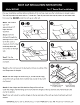
Key No. Part No. Description
1 97016971 Fan Switch – White (Includes Light Switch)
97016972 Fan Switch – Almond (Includes Light Switch)
97016970 Fan Switch – Black (Includes Light Switch)
97016973 Fan Switch – Biscuit (Includes Light Switch)
2 97016971 Light Switch – White (Includes Fan Switch)
97016972 Light Switch – Almond (Includes Fan Switch)
97016970 Light Switch – Black (Includes Fan Switch)
97016973 Light Switch – Biscuit (Includes Fan Switch)
3 R730088 Motor/Blade Assembly
4 R610045
Filter - Aluminum (use with ducted hoods only)
* R610050 Filter – Ductless
* R610051 Filter Pads – Ductless
5 R566088 Lampholder
6 99091020 Vent Cover - White
99091021 Vent Cover - Almond
99091022 Vent Cover - Black
99091027 Vent Cover - Biscuit
7 R6689601 Wiring Cover - White
R6689602 Wiring Cover - Almond
R6689604 Wiring Cover - Black
R6689605 Wiring Cover - Biscuit
REPLACEMENT PARTS
* Not shown. Purchase separately.
1
2
3
4
5
7
6
Replacement parts
can be ordered on our
website at
www.Broan.com
BROAN-NUTONE ONE YEAR LIMITED WARRANTY
Broan-NuTone warrants to the original consumer purchaser of its products that such products will be free from defects in
materials or workmanship for a period of one year from the date of original purchase. THERE ARE NO OTHER WARRANTIES,
EXPRESS OR IMPLIED, INCLUDING, BUT NOT LIMITED TO, IMPLIED WARRANTIES OF MERCHANTABILITY OR FITNESS
FOR A PARTICULAR PURPOSE.
During this one-year period, Broan-NuTone will, at its option, repair or replace, without charge, any product or part which is
found to be defective under normal use and service.
THIS WARRANTY DOES NOT EXTEND TO FLUORESCENT LAMP STARTERS, TUBES, HALOGEN AND INCANDESCENT
BULBS, FUSES, FILTERS, DUCTS, ROOF CAPS, WALL CAPS AND OTHER ACCESSORIES FOR DUCTING. This warranty does
not cover (a) normal maintenance and service or (b) any products or parts which have been subject to misuse, negligence,
accident, improper maintenance or repair (other than by Broan-NuTone), faulty installation or installation contrary to
recommended installation instructions.
The duration of any implied warranty is limited to the one-year period as specified for the express warranty. Some states do not
allow limitation on how long an implied warranty lasts, so the above limitation may not apply to you.
BROAN-NUTONE’S OBLIGATION TO REPAIR OR REPLACE, AT BROAN-NUTONE’S OPTION, SHALL BE THE PURCHASER’S
SOLE AND EXCLUSIVE REMEDY UNDER THIS WARRANTY. BROAN-NUTONE SHALL NOT BE LIABLE FOR INCIDENTAL,
CONSEQUENTIAL OR SPECIAL DAMAGES ARISING OUT OF OR IN CONNECTION WITH PRODUCT USE OR PERFORMANCE.
Some states do not allow the exclusion or limitation of incidental or consequential damages, so the above limitation or
exclusion may not apply to you.
This warranty gives you specific legal rights, and you may also have other rights, which vary from state to state. This warranty
supersedes all prior warranties.
To qualify for warranty service, you must (a) notify Broan-NuTone at the address or telephone number below, (b) give the model
number and part identification and (c) describe the nature of any defect in the product or part. At the time of requesting warranty
service, you must present evidence of the original purchase date.
Broan-NuTone LLC, 926 W. State Street, Hartford, Wisconsin 53027 www.broan.com 800-558-1711
  • Page 1 1
  • Page 2 2
  • Page 3 3
  • Page 4 4
  • Page 5 5
  • Page 6 6
  • Page 7 7
  • Page 8 8

Broan 433004 User manual

Category
Cooker hoods
Type
User manual

Ask a question and I''ll find the answer in the document

Finding information in a document is now easier with AI

in other languages