2 3 4
6 7 85
- Adern auf dem kürzesten Weg in die Klemmleiste ein-
führen, zulässiger Adernquerschnitt beachten.
- Zulässiges Drehmoment der Schraubklemme 0,4 Nm/M 2,6.
- Überkreuzungen der Datenleitungen mit den Leitungen
der Betriebsspannung muss vermieden werden.
Anzugsdrehmoment
Klemmleiste/Schraubklemme max. 0,4 Nm
(empfohlenes Anzugsdrehmoment 0,3 Nm)
Verschraubung Bushaube max. 1,9 Nm
Kupplungsfederbefestigung max. 1,2 Nm
Klemmringbefestigung max. 1,2 Nm
Aderquerschnitt
Eindrahtig (starr) Max. 1,5 mm
2
Feindrahtig (exibel) Max. 1,0 mm
2
Feindrahtig (exibel) Isolierte Aderendhülse
max. 0,75 mm
2
Kabeldurchmesser
Kabelverschraubung 1, 2 8...10 mm (-40...+85 °C)
5...9 mm (-25...+85 °C)
Kabelverschraubung 3 4,5...6 mm
Anschlussbelegung
CAN_L CAN Bus Signal (dominant Low)
CAN_H CAN Bus Signal (dominant High)
UB Betriebsspannung 10...30 VDC
GND Masseanschluss bezogen auf UB
Klemmen mit gleicher Bezeichnung sind intern verbun-
den und funktionsidentisch. Diese internen Klemmverbin-
dungen UB-UB und GND-GND dürfen mit max. je 1 A be-
lastet werden.
- Bushaube vorsichtig auf den D-SUB Stecker vom Basis-
geber aufstecken, dann über den Dichtgummi drücken
und nicht verkanten. Bushaube muss vollständig am
Basisgeber anliegen.
- Befestigungsschrauben gleichsinnig fest anziehen.
- Drehgebergehäuse und Schirmgeecht des Anschluss-
kabels sind nur dann optimal verbunden, wenn die
Bushaube vollständig auf dem Basisgeber auiegt
(Formschluss).
Ader
Schirmfolie
Dichteinsatz
Schirmgeflecht KabelHutmutter
Gefahr
Warnung bei möglichen Gefahren.
Hinweis
Info für bestimmungsgerechte Produkthandhabung.
Allgemeiner Hinweis
Zusätzliche Informationen
Die Montageanleitung ist eine Ergänzung zu weiteren
Dokumentationen (z. B. Katalog, Datenblatt, Handbuch).
Anleitung unbedingt vor Inbetriebnahme lesen.
Bestimmungsgemässer Gebrauch
- Der Drehgeber ist ein Präzisionsmessgerät. Er dient zur
Erfassung von Winkelpositionen und Umdrehungen,
Aufbereitung und Bereitstellung von Messwerten als
elektrische Ausgangssignale für das Folgegerät. Dreh-
geber nur zu diesem Zweck verwenden.
Inbetriebnahme
- Einbau und Montage des Drehgebers darf ausschliess-
lich durch eine Fachkraft erfolgen.
- Betriebsanleitung des Maschinenherstellers beachten.
Sicherheitshinweise
- Vor Inbetriebnahme der Anlage alle elektrischen Verbin-
dungen überprüfen.
- Wenn Montage, elektrischer Anschluss oder sonstige
Arbeiten am Drehgeber und an der Anlage nicht fachge-
recht ausgeführt werden, kann es zu Fehlfunktion oder
Ausfall des Drehgebers führen.
- Eine Gefährdung von Personen, eine Beschädigung
der Anlage und eine Beschädigung von Betriebseinrich-
tungen durch den Ausfall oder Fehlfunktion des Dreh-
gebers muss durch geeignete Sicherheitsmassnahmen
ausgeschlossen werden.
- Drehgeber nicht ausserhalb der Grenzwerte betreiben,
welche im Datenblatt angegeben sind.
Bei Nichtbeachtung der Sicherheitshinweise kann es zu
Fehlfunktionen, Sach- und Personenschäden kommen.
Entsorgung
Bestandteile nach länderspezischen Vorschriften entsorgen.
Transport und Lagerung
- Ausschliesslich in Originalverpackung.
- Drehgeber nicht fallen lassen oder grösseren Erschütte-
rungen aussetzen.
Montage
- Vor Montage des Drehgebers, Klemmring vollständig
öffnen.
- Schläge oder Schocks auf Gehäuse und Welle vermeiden.
- Gehäuse nicht verspannen.
- Drehgeber nicht öffnen oder mechanisch verändern.
- Federarme der Kupplungsfeder müssen frei beweglich sein.
Hohlwelle, Kugellager, Glasscheibe oder elektro-
nische Teile können beschädigt werden. Die si-
chere Funktion ist dann nicht mehr gewährleistet.
Hohlwellen-Befestigung
Klemmringbefestigung
Drehgeber auf die Antriebswelle (ISO-Passung f7) voll-
ständig aufstecken und den Klemmring fest anziehen. Die
Antriebswelle muss mindestens 35 mm in die Hohlwelle
des Drehgebers eintauchen.
Mechanischer Anbau
Drehgeber über die Antriebswelle schieben und Drehmo-
mentstift in das kundenseitige Justierteil einführen oder in
das kundenseitig montierte Justierteil (mit Gummifedere-
lement) einführen.
Kupplungsfeder
Kupplungsfeder mit den Schrauben an den Befestigungslöchern des Gehäuses
montieren. Drehgeber über die Antriebswelle schieben. Kupplungsfeder an der Anla-
geäche befestigen.
(23.5)
(9.5)
15
ø4 fg6
Drehmomentstift
Alle beweglichen Justierelemente müssen in axialer und
radialer Richtung Spiel haben, um Verschiebungen durch
Temperatur und mechanisches Spiel auszugleichen. Be-
festigungsschrauben bzw. Schrauben des Klemmrings
fest anziehen.
Elektrische Inbetriebnahme
- Drehgeber elektrisch nicht verändern und keine Ver-
drahtungsarbeiten unter Spannung vornehmen.
- Der elektrische Anschluss darf unter Spannung nicht
aufgesteckt oder abgenommen werden.
- Bei Verbrauchern mit hohen Störpegeln separate Span-
nungsversorgung für den Drehgeber bereitstellen.
- Die gesamte Anlage EMV gerecht installieren.
Einbauumgebung und Verkabelung beeinussen die
EMV des Drehgebers. Drehgeber und Zuleitungen
räumlich getrennt oder in grossem Abstand zu Lei-
tungen mit hohem Störpegel (Frequenzumrichter, Schüt-
ze usw.) verlegen.
- Gebergehäuse und die Anschlusskabel vollständig
schirmen.
- Drehgeber an Schutzerde (PE) anschliessen. Ge-
schirmte Kabel verwenden. Schirmgeecht muss mit der
Kabelverschraubung oder Stecker verbunden sein. An-
zustreben ist ein beidseitiger Anschluss an Schutzerde
(PE). Gehäuse über den mechanischen Anbau erden,
bei elektrisch isoliertem Anbau zusätzliche Verbindung
herstellen.
- Kabelschirm über die nachfolgenden angeschlossenen
Geräte erden. Bei Problemen mit Erdschleifen minde-
stens eine einseitige Erdung.
Bei Nichtbeachtung kann es zu Fehlfunktionen, Sach-
und Personenschäden kommen.
Elektrischer Anschluss
Bushaube ausschliesslich im ESD Beutel lagern und
transportieren. Bushaube muss vollständig am Gehäuse
anliegen und fest verschraubt sein.
- Beide Befestigungsschrauben der Bushaube lösen
- Beide Bushaubenteile vorsichtig lockern und axial ab-
ziehen.
- Teilnehmeradresse an beiden dezimalen Drehschaltern
einstellen. Teilnehmeradresse zum Beispiel 23.
- Abschlusswiderstände müssen beim letzten Teilnehmer
mit dem 2-poligen DIP Schalter auf „ON“ geschaltet
werden (Werkseinstellung Off).
Schalter 1:
ON = Letzter Teilnehmer / OFF = Teilnehmer X
Schalter 2: ohne Funktion
Baudrate Einstellung Dip-Schalter
1 2 3
10 kBit/s OFF OFF OFF
20 OFF OFF ON
50 OFF ON OFF
125 OFF ON ON
250 ON OFF OFF
500 ON OFF ON
800 kBit/s ON ON OFF
1 MBit/s ON ON ON
Bei Einstellung Teilnehmeradresse 00 kann die Baudrate über
den CAN-Bus programmiert werden.
Anschluss – Kabelverschraubung (Bushaube)
- Hutmutter der Kabelverschraubung lösen. Hutmutter
und Dichteinsatz auf den Kabelmantel schieben.
- Kabelmantel und Adern abisolieren, Schirmfolie, falls
vorhanden, kürzen (s. Bild).
- Schirmgeecht um ca. 90° umbiegen.
- Dichteinsatz bis an das Schirmgeecht schieben. Dicht-
einsatz und Kabel bündig in die Kabelverschraubung
einführen und Hutmutter fest verschrauben.
- Für die Betriebsspannung ausschliesslich Kabelver-
schraubung 3 verwenden. Für die Busleitungen können
frei wählbar Kabelverschraubung 1 oder 2 verwendet-
werden. Zulässige Kabelquerschnitte beachten.
- Isolierte Aderendhülsen verwenden.
Kabel
33
12
Antriebs-
welle
Klemmring
CAN_L
CAN_H
UB
GND
CAN_L
CAN_H
UB
GND
1 2
3
Printed in Germany · 07.15 · 178.51.180/8 · 81005077
Irrtum sowie Änderungen in Technik
und Design vorbehalten.
Subject to modication in technic and design.
Errors and omissions excepted.
Baumer IVO GmbH & Co. KG
Dauchinger Strasse 58-62
DE-78056 Villingen-Schwenningen
Phone +49 7720 942-0
Fax +49 7720 942-900
www.baumer.com
G0AMH, G0LMH, G0MMH
GBAMH, GBLMH, GBMMH
GEMMH
Absolute Drehgeber – CANopen 2-8
Absolute encoder – CANopen 9-16
Montageanleitung
Assembly Instructions
DE
GB
0.3
6.6
40.5
7.5
M3
(1.2 Nm)
35
10
15.1
19.1
7.6
7.6
M3 (1.2 Nm)
SW2.5
20
73
12
M3 (1.2 Nm)
SW2.5
±0.5
20
68
M3 (1.2 Nm)
SW2.5
12
11
4.5
10.5
53.5
63.75 20.5
95.75 20.5
30
7
0.3
12
Ader
43
Busleitung
Versorgungsleitung
ON
40.5
20.5
38
5
±0.5
1.25
Drehmomentstift
Justierteil
Gummifeder-
element
Justierteil mit
Drehmomentstift 9.5 mm
2.5
22
30°
25°
R37.25
R43.5
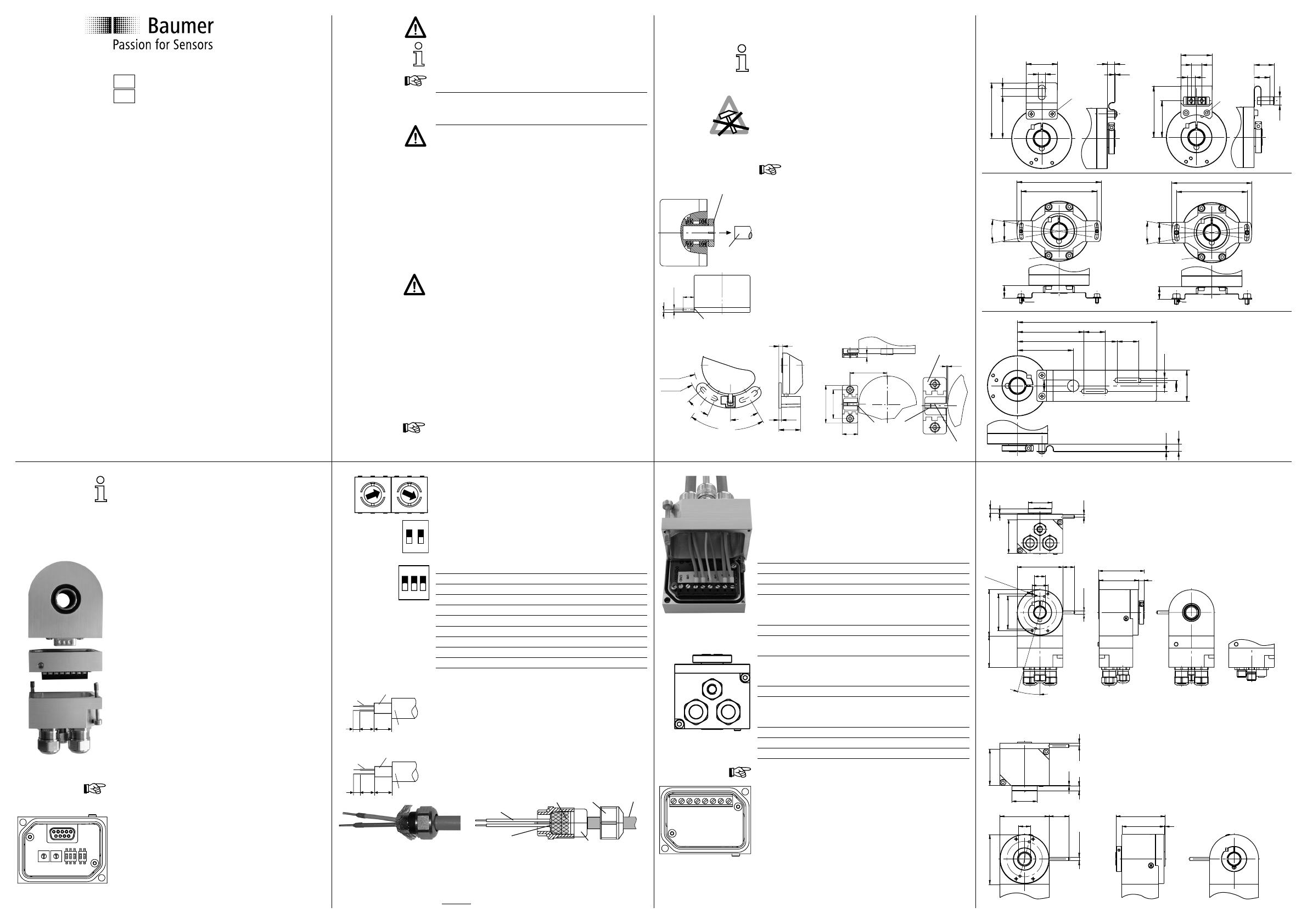
Abmessungen
Klemmring anschseitig
Klemmring gehäuseseitig
ø10-14 H7
ø4 fg6
50
43
1
58
59
58 15 (23.5)
ø30
0.5
6
3.5
ø10-14 H7
1
6
3.5ø4fg6
58 15
5940
7.5
50
58
43
47
42
20
15°
M3 x 6 (6x)

