Broan C3B(A,H)-0 Installation guide

Type
Installation guide
Installation Instructions
Split System Uncased Indoor Coils
These instructions are primarily intended to assist qualified individuals experienced in the proper installation
of this appliance. Some local and national codes require licensed installation/service personnel for this type
of equipment. Read all instructions carefully before starting the installation.
CAUTION:
Read the Installation Instructions supplied with furnace/air handler and observe all safety
requirements outlined in instructions and/or furnace/air handler markings before proceeding
with installation of the coil.
2
1. GENERAL INFORMATION
These series coils are designed for upflow and downflow
applications. They are equipped with brazing stub refrigerant
connections for easy installation. Horizontal conversion
kits are available. Refer to the Specifications Table below
for more information.
Read the installation manual supplied with the outdoor unit
for refrigerant line connection procedure, required line
sizes, and other information pertaining to the system
installation.
1. Make certain that the air delivery of the furnace/air
handler is adequate to handle the static pressure drop
of the coil, filter, and duct work.
2. Check the coil's orifice size and confirm that it is
suitable for application with the intended outdoor unit.
3. Where precise forming of the refrigerant lines is required,
a copper tubing bender designed for the size lines used
is recommended. Avoid sharp bends and contact of the
refrigerant lines with metal surfaces.
4. Refrigerant lines should be wrapped with pressure
sensitive neoprene or other suitable material where
they pass through the raw edges of holes.
5. Coil enclosure and suction line must be insulated.
6. Coil must be level for proper condensate drainage.
NOTE: Optional cooling/heating equipment must be properly
sized and installed in accordance with the furnace
manufacturer’s specifications and approved
recommendations. “Heating only” furnace air circulators
may have to be replaced with multi-speed “Heating/Cooling”
blowers to upgrade the air delivery (CFM) when an add-on
coil is installed. Refer to Coil Specifications for recommended
CFM and allow for pressure drop across the coil and filters.
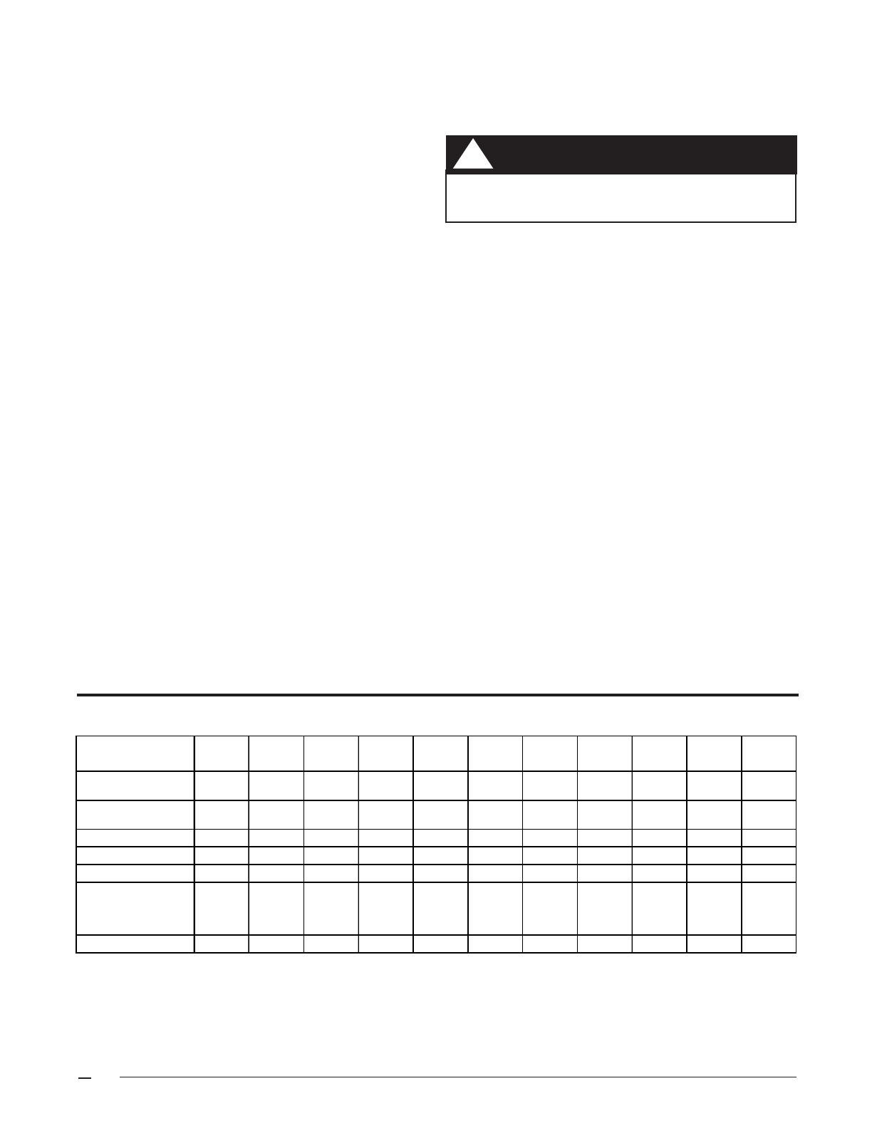
1.Refer to sales specification sheets for Listed/Certified combinations of equipment and required accessories.
2.Refer to the current ARI Directory for certified ratings of split systems.
3.Based on a nominal 0.3" w.c. pressure drop across the coil.
3. COIL INSTALLATION
Upflow Furnace:
1. Disconnect all electrical power to the furnace.
2. If needed, make a plate to adapt the coil to the furnace/
air handler air discharge opening.
3. Install the coil and level it as needed to allow proper
condensate drainage.
4. Make a plenum to enclose the coil or drop the duct
directly over it. Insulate as required. (See Figure 2)
5. Seal the enclosure as required to minimize air
leakage.
6. Connect the refrigerant lines as outlined in
the Refrigerant Lines section.
Downflow/Horizontal — These coils may be installed in
downflow or horizontal applications. Installation of the
coils in these applications only requires that the coil be
securely mounted and that the proper horizontal drain kit be
added. Refer to the Specifications section for the proper kit
numbers.
NOTE: If the coil is installed horizontally, a drain kit must
be used.
WARNING:
Electric furnaces may be connected to more
than one supply circuit.
!
2. COIL SPECIFICATIONS
Coil C3BA C3BA C3BA C3BA C3BA C3BA C3BM C3BA C3BA C3BA C3BA
Model (1) 024U-A 030U-A 036U-A 043U-A 030U-B 036U-B 036U-B 042U-B 048U-B 048U-C 060U-C
Nominal (2)
Ca
p
acit
y
BTUH
24,000 30,000 36,000 43,000 30,000 36,000 36,000 42,000 48,000 48,000 60,000
Nominal Airflow
CFM
(
3
)
900 1,125 1,200 1,400 1,100 1,350 1,350 1,500 1,500 1,600 1,800
Orifice Size (in.)
0.060 0.063 0.067 0.080 0.063 0.067 0.067 0.075 0.080 0.080 0.093
Width (in.) W
12 3/4 12 3/4 12 3/4 12 3/4 18 1/8 18 1/8 18 1/8 18 1/8 18 1/8 21 21
Height (in.) H
13 18 7/8 19 1/2 23 1/4 19 1/2 19 1/2 15 19 1/2 19 1/2 19 1/2 23 1/4
Connections
(
in.
)
Li
q
uid Line
3/8 3/8 3/8 3/8 3/8 3/8 3/8 3/8 3/8 3/8 3/8
Suction Line
3/4 3/4 3/4 3/4 3/4 3/4 3/4 3/4 3/4 3/4 7/8
Horiz. Drain Kit
914633 917492 917492 914634 914633 914633 914633 914633 914633 914633 914634
3
Figure 2
Figure 1. B & C Cabinet Coil
4. REFRIGERANT LINE CONNECTIONS
NOTE: Before proceeding with the connection of the
refrigerant lines, confirm that the orifice size meets the
requirements outlined in the outdoor unit installation manual.
Factory installed orifice sizes are listed in the
Specifications section. If the restrictor orifice must be
replaced, follow the steps below:
1. Loosen the orifice body halves by applying two
wrenches and squeezing them together as shown in
Figure 3, to turn the assembly nut counter- clockwise.
2. Continue to unscrew the assembly nut to separate it
from the distributor body.
3. Insert a light-gauge wire hook between the distributor
body and the restrictor orifice to lift the orifice out of
the body. (See Figure4) Carefully remove the restrictor
orifice being careful not to scratch either part.
4. Check the actual size of the new orifice. The size
is stamped on its side. Do not use pin gages to
measure the orifice diameter.
5. Insert the new orifice in the distributor body, rounded
end down. (See Figure 5)
6. After installing the orifice in the distributor body,
realign the assembly nut to the distributor body.
Mark a line along both bodies after hand tightening
and then tighten an additional 1/4 turn. Caution: Do
not overtighten! The misalignment of the two lines
will show how much the nut is tightened. If a torque
wrench is used, tighten to 10-12 ft. lbs. or 14-16
Nm.
7. Remove the protective caps from the coil and
refrigerant line set.
8. Cut the line set tubing to the proper length. Be sure
that the tubing has been sized in accord-ance with
the outdoor unit specifications.
9. Inspect both refrigerant lines. The ends of the lines
must be round, clean, and free of any burrs.
10. Insert the line set tubes into the coil tube stubs until
they bottom out.
11. Braze the individual connections with dry nitrogen
flowing through the joints to eliminate internal
oxidation and scaling.
12. Check the assembly for leaks with dry nitrogen.
5. COMPLETING THE INSTALLATION
The indoor coil must be checked to ensure a
level installation. Failure to do so may result in
improper condensate disposal, causing
structural damage, premature equipment
failure, or possible personal injury.
CAUTION:
!
Condensate Drain:
1. The coil condensate pan is furnished with 3/4" NPSC
drain connections. Use a PVC or similar material fitting
to attach the drain line to the pan. The fitting should be
only hand tightened.
Overtightening may crack the drain pan and create
a condensate leak.
2. Connect the drain line and run to a suitable drain
avoiding sharp bends and pinching of the line. Install a
condensate trap and prime with water.
3. During the system checkout, inspect the drain line and
connections to verify proper condensate disposal.
Air Filter — Air filters are not provided as an integral part
of this coil, however, a filter must be installed upstream of
the coil and inspected frequently. When the filter becomes
clogged with dust or lint, it should be replaced (disposable
type) or cleaned (washable type). The filter should be
inspected and replaced or cleaned at least twice during the
year, generally at the start of each heating and cooling
season.
Figure 5. Restrictor Insertion in Distributor Body
Figure 3. Wrenches on Distributor Body
and Assembly Nut
CERTIFICATION APPLIES ONLY
WHEN THE COMPLETE
SYSTEM IS LISTED
WITH ARI
7082330 (Replaces 707742C)
Specifications and illustrations subject to change
without notice and without incurring obligations.
Printed in U.S.A. (2/03)
Close-Off Plates and Panels — Install the necessary air
close-off plates around the refrigerant lines and drain line
where required. Reinstall all inner and outer panels of the
furnace/air handler that were previously removed to install
the indoor coil.
Refrigerant Charging — These indoor coils are not factory
charged with refrigerant.
It will be necessary to evacuate the indoor coil and line set
prior to charging. Refer to the outdoor unit installation
manual for detailed charging instructions.
6. MAINTENANCE AND SERVICE
CAUTION:
Do not operate the system without having a
suitable filter in place in the return air duct
system. Always replace the filter with the
same size and type.
!
WARNING:
Ensure that all electrical power to the furnace
and outdoor (condensing) unit is off before
performing any maintenance or service on the
system.
!
Figure 4. Removal of Orifice
To ensure optimum system performance and to minimize
the possibility of equipment failure, the following periodic
maintenance should be performed on the coil:
1. The air filter installed with the system should be checked
and cleaned or replaced twice per year.
2. Check the coil, drain pan, and condensate drain line for
cleanliness at the start of each heating and cooling
season. Clean and remove any debris as required.
INSTALLER: PLEASE LEAVE
THESE INSTALLATION
INSTRUCTIONS WITH THE
HOMEOWNER
¢708233«¤
7082330
®
A
S
C
O
M
P
L
Y
I
I
T
N
G
W
H
T
T
H
N
I
S
U
I
H
A
S
B
I
D
D
A
R
I
S
T
A
N
A
R
2
1
0
T
A
I
D
N
F
I
E
D
T
R
E
C
E
E
N
R
-
C
O
I
I
O
N
I
N
G
T
A
I
D
N
R
-
C
O
I
I
O
N
I
N
G
D
I
T
I
O
N
I
N
G
N
O
C
-
R
I
A
®
T
O
A
R
I
A
S
C
O
M
P
L
Y
I
I
T
N
G
W
H
T
T
M
A
A
N
U
F
C
U
R
E
R
E
E
D
R
C
F
I
I
D
D
A
R
I
S
T
A
N
A
R
2
4
0
T
A
R
Y
I
N
U
H
E
A
T
P
P
U
M
P
E
Q
U
I
M
E
N
T
  • Page 1 1
  • Page 2 2
  • Page 3 3
  • Page 4 4

Broan C3B(A,H)-0 Installation guide

Type
Installation guide

Ask a question and I''ll find the answer in the document

Finding information in a document is now easier with AI