Broan GP5RD User manual

Category
Fireplaces
Type
User manual
Single Package Cooling Unit or Heat Pump Unit
IMPORTANT! Please read all information in this manual thoroughly and become familiar with the capabilities and use
of your appliance before attempting to operate or maintain this unit. Pay attention to all safety warnings and any other
special notes highlighted in the manual. Safety markings are used frequently throughout this manual to designate
a degree or level of seriousness and should not be ignored. WARNING indicates a potentially hazardous situation
that if not avoided, could result in personal injury or death. CAUTION indicates a potentially hazardous situation that
if not avoided, may result in minor or moderate injury or property damage. Keep this literature where you have easy
access to it in the future. If a problem occurs, check the instructions and follow recommendations given. If these
suggestions don’t eliminate your problem, call your servicing contractor. Do not attempt to service this unit yourself!
 
           
          


 

          
           

 


WARNING:
!

2


WARNING:



     

  


WARNING:




• Toachieveoptimumperformanceandminimizeequipment
failure, it is recommended that periodic maintenance be
performed on this unit. The ability to properly perform
maintenance on this equipment requires certain mechanical
skills and tools.
• Theareaaroundtheunitandthevicinityofanyotherappliances
must be kept clear and free of combustible materials and
other flammable vapors and liquids. Some examples of these
chemicals are:
Gasoline / Kerosene
Permanent wave solutions
Chlorinated waxes and cleaners
Chlorine based swimming pool chemicals
Water softening chemicals
De-icing salts or chemicals
Carbon tetrachloride
Halogen type refrigerants
Cleaning solvents
Cements, glues, paint removers, varnishes, etc.
Hydrochloric acid
Masonry acid washing materials
• The top and sides of the unit must be open and clear of
obstructions for proper airflow. Do not place anything on top of
thefangrilleorwithin12inchesofall4sidesoftheunit.These
clearances must be maintained to achieve rated performance.
Do not use the area around the unit as a storage area.
• Donotusethisapplianceifanyparthasbeenunderwater.
Immediately call a qualified service technician to inspect the
unit and to replace any part of the electrical control system
that has been under water.
• Familiarizeyourselfwiththecontrolsthatshutofftheelectrical
power to the unit. If the unit is to be shut down for an extended
periodoftime,turnofftheelectricalpower.Foryoursafety
always turn off the electrical power before performing service
or maintenance.
• Donotblockorobstructairopeningsontheunitorairopenings
supplying the area where it is installed.
• Theductconnectionsmustbephysicallysoundandsealed
totheunit’scasing.Thereturnairandcirculatingairductwork
must not be connected to any other heat producing device
such as a fireplace insert, stove, etc. Improperly installed
ductwork may result in fire, explosion, personal injury, carbon
monoxide poisoning, or property damage.

BeforeyoucallaTechnician,checkthefollowing:
• Checkthethermostatsetting.Makesurethesystemmode
and temperature settings are correct.
• Checktheelectricalpanelfortrippedcircuitbreakers.
• Checktheltersfordustaccumulation.
• Checktheunitandmakesureitiscleanandnotcoveredwith
grass or leaves.
• Iftheitemsabovedon’tresolveyourproblems,thencallyour
installing dealer.

A warranty certificate with full details is included with the
equipment. Carefully review these responsibilities with your dealer
orservicecompany.Themanufacturerwillnotberesponsiblefor
any costs found necessary to correct problems due to improper
setup, improper installation, adjustments, improper operating
procedure on the part of the user. Some specific examples of
service calls which are not included in the limited warranty are:
• Correctingwiringproblemsintheelectricalcircuitsupplying
the equipment.
• Resettingcircuitbreakersorotherswitches.
• Adjustingorcalibratingofthermostat.
3

The single packaged electric cooling unit is a high efcient
self contained appliance that will cool your home and provide
energy saving comfort. Additional features and benefits of the
cooling include:
• Indoorandoutdoorcoilsaredesignedtooptimizeheattransfer,
minimize size and cost, and increase durability and reliability.
• EnvironmentallyfriendlyR-410ARefrigerant.

Thermostat styles vary. Some models may not include the
AUTO mode and others will have the AUTO in place of the
HEATandCOOL.Others mayinclude allthree.Please refer
to the thermostat manufacturer’s User manual for detailed
programming instructions.
Thethermostatshouldbemountedabout5feetabovetheoor
on an inside wall and not on an outside wall or other location
where its operation may be adversely affected by radiant heat
from fireplaces, sunlight, or lighting fixtures, and convective heat
from warm air registers or electrical appliances.
Cooling Operation - 1 or 2-Stage Operation
1. SetthethermostatsystemmodetoCOOLandthethermostat
fanmodetoAUTO.SeeFigure1.
2. Set the thermostat temperature selector to the desired
temperature level. The outdoor fan, compressor, and
indoor blower will all cycle on and off to maintain the indoor
temperature at the desired cooling level.

• Onsomeselectmodels,ifthecoolinglevelisnotsatisifed
by the thermostat in stage 1, the thermostat will initiate
to stage 2 and the indoor blower will ramp to a higher
speed.
• Ifthetemperaturelevelisre-adjusted,orthesystemmode
is reset, the fan and compressor in the outdoor unit may
notstart immediately.Theremaybeaprotectivetimer
circuit in the thermostat which holds the compressor and
theoutdoorfanoffforapproximately5minutesfollowinga
previous operation or the interruption of the main electrical
power.



Temperature
Selector



1. Set the thermostat system mode to Heat and the thermostat
fanmodetoAUTO.SeeFigure1.
2. Set the thermostat temperature selector to the desired
temperaturelevel.Theindoorblowerorelectricheatmodule
will cycle on and off to maintain the indoor temperature at
the desired heating level.

SetthethermostatsystemmodetoOFFandthethermostatfan
modetoAUTO.SeeFigure1.Thesystemwillnotoperate,
regardless of the thermostat temperature selector’s setting.

SetthethermostatfanmodetoON(orCONTonsomethermostat
models).SeeFigure1.
Theindoorblowerwillstartimmediately,andwillruncontinually
untilthefanmodeisresettoAUTO.
Thecontinuousindoorbloweroperationcanbeobtainedwith
thethermostatsystemmodesetinanyposition,includingOFF.
The continuous indoor blower operation is typically used to
circulate the indoor air to equalize a temperature imbalance due
to a solar load, cooking, or fireplace operation.

4


Your heat pump is a unique, all weather comfort-control appliance
that will heat and cool your building year round and provide
energy saving comfort. It’s an unknown fact that heat is always
in the air, even when the outside temperature is below freezing.
Theheatpumpusesbasiclawsofphysicstoprovideenergy
saving heat during the winter months.
In colder temperatures, the heat pump performs like an air
conditioner run in reverse. Available heat energy outside the
building is absorbed by the refrigerant and exhausted inside.
Thisefcientprocessmeansyouonlypayfor“moving”theheat
from the outdoors to the indoor area. You do not pay to generate
the heat, as is the case with more traditional furnace designs.
During summer, the heat pump reverses the flow of the heat-
absorbing refrigerant to become an energy-efficient, central air
conditioner.Excessheatenergyinsidethehomeisabsorbed
by the refrigerant and exhausted outside the building.

Thermostatstylesvary.SomemodelswillnotincludetheAUTO
mode and others will have the AUTO in place of the HEAT
andCOOL.Others mayinclude all three.Please referto the
thermostat manufacturer’s User Manual for detailed programming
instructions.
Thethermostatshouldbemountedabout5feetabovetheoor
on an inside wall and not on an outside wall or other location
where its operation may be adversely affected by radiant heat
from fireplaces, sunlight, or lighting fixtures, and convective heat
from warm air registers or electrical appliances.
 If the temperature level is re-adjusted, or the system mode
is reset, the fan and compressor in the outdoor unit may not
start immediately. A protective timer circuit holds the compressor
andtheoutdoorfanoffforapproximately5minutesfollowinga
previous operation or the interruption of the main electrical power.
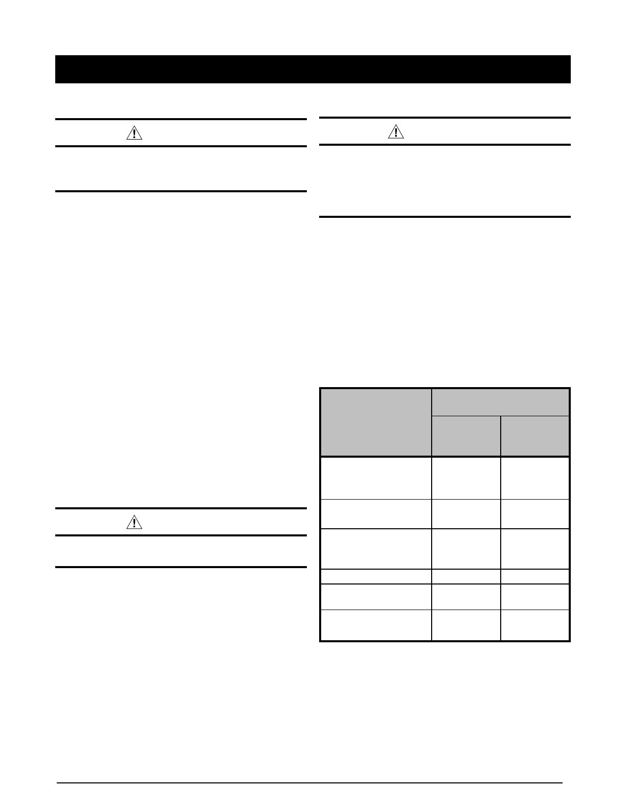
Cooling Operation (1 or 2 Stage Operation)
1. SetthethermostatsystemmodetoCOOLandthethermostat
fanmodetoAUTO.SeeFigure1.
2. Set the thermostat temperature selector to the desired
temperature level. The outdoor fan, compressor, and
indoor blower will all cycle on and off to maintain the indoor
temperature at the desired cooling level.
Onsomeselectmodels,ifthecoolinglevelisnot
satisifed by the thermostat in stage 1, the thermostat will
initiate to stage 2 and the indoor blower will ramp to a higher
speed.

1. Setthethermostat’ssystemmodetoHEATorAUTOand
changethefanmodetoAUTO.SeeFigure1(pg3).
2. Set the temperature selector to the desired temperature
level.Thecompressor,outdoorfan,andblowermotorwill
cycle on and off to maintain the indoor temperature at the
desired heating level.

• Iftheheatinglevelisnotsatisifedbythethermostatin
stage 1, the thermostat will initiate to stage 2 and the
indoor blower will ramp to a higher speed.
• Onsomethermostats,iftheheatingloadontheconditioned
space is not met in a normal period of time or the difference
between the thermostat set point and room temperature
is large, the heat pump will automatically shut off and the
electric heat will operate until the thermostat demand for
heat is met.

HeatpumpthermostatsincludeasystemmodecalledEMHT
orAUXHT,etc.Thisisaback-upheatingmodethatshouldonly
beusedifaproblemissuspected.WiththemodesettoEM
HT,etc.,thecompressorandoutdoorfanwillbelockedoffand
electric heat will be used as a source of heat. Sustained use of
electric heat in place of the heat pump will result in an increase
inthisutilitycost.Refertothethermostatmanualformoreinfo.

During cold weather heating operation, the outdoor unit will
developacoatingofsnowandiceontheheattransfercoil.This
isnormalandtheunitwilldefrostitself.Thisunitwillmonitor
ambient and coil temperatures to regulate the defrost function
accordingly.
At the beginning of the defrost cycle, both the outdoor condenser
fanandcompressorwillturnoff.Afterapproximately30seconds,
the compressor will turn on and begin to heat the outdoor coil
causing the ice and snow to melt.
During the defrost period, the electric heat will energize and
produce warm air to offset the heat pump operation while in its
reverse cycle. Initially the air out of the supply registers may
be slightly cooler since the heat pump has reversed its cycle
and is now in the cooling mode to aide in the defrosting of the
outdoorcoil.Theairwillriseintemperatureastheelectricheat
continues to operate.
 While the ice and snow is melting, some steam may
rise from the outdoor unit as the warm coil causes the melting
frost to evaporate. When defrost is completed, the outdoor
fan motor will start, and the compressor will turn off again. In
approximately30secondsthecompressorwillstartupagain
andcontinuenormaloperation.Theelectricheatwillshutdown
at the end of the defrost cycle.

1. SetthethermostatsystemmodetoAUTOandthethermostat
fanmodetoAUTO.SeeFigure1(page3).
2. Set the thermostat’s temperature selector to the desired
heatingandcoolingtemperaturelevel(s).Theoutdoorunit
and the indoor blower will then cycle on and off in either
the heating or cooling mode of operation as required to
automatically maintain the indoor temperature within the
desired limits.

The continuous indoor blower operation is typically used to
circulate the indoor air to equalize a temperature imbalance
due to a solar load, cooking, or fireplace operation. Set the
thermostat fan mode (Figure 1) to ON (or CONT on some
thermostatmodels).Theindoorblowerwillstartimmediately,
andwillruncontinuallyuntil thefanmodeisreset to AUTO.
Thecontinuousindoorbloweroperationcanbeobtainedwith
thethermostatsystemmodesetinanyposition,includingOFF.

Set the thermostat systemmode (Figure1) toOFF andthe
thermostatfanmodetoAUTO.Thesystemwillnotoperate,
regardless of the thermostat temperature selector’s setting.
5


CAUTION:


maintenance.
Thissinglepackagecooling/heatpumpappliancehasbeen
testedforcapacityandefciencyinaccordancewithA.H.R.I.
Standards and will provide many years of safe and dependable
comfort, providing it is properly installed and maintained. With
regular maintenance, this unit will operate satisfactorily year after
year. Abuse, improper use, and/or improper maintenance can
shorten the life of the appliance and create unsafe hazards. A
regular service and maintenance schedule should be established
to ensure efficient and safe operation of the unit.
Proper maintenance is most important to achieve the best
performance from the appliance and should be performed by
aqualiedservicetechnicianatleastonceayear.Followthe
maintenance schedule and the instructions below for years of
safe, trouble free operation.
• Annuallyinspectthephysicalsupportoftheunittoensure
that it is physically sound without sagging, cracks, gaps, etc.,
around the base so as to provide a seal between the support
and the base.
• Annuallyinspectthereturn-airconnectionto ensurethatit
is physically sound and is still sealed to the casing of the
unit. Also inspect the unit and ductwork for signs of physical
deterioration.
• Alwaysreplacethedoorsontheunitafterservicing.Donot
operate the unit without all doors and covers in place. Avoid
operating the unit when windows and doors are open.
• Refer to the Maintenance Schedule for recommended
maintenance information.
Regular Cleaning
CAUTION:


• Removeanyleavesandgrassclippingsfromtheoutdoorcoil.
.
Check for and remove any obstructions such as twigs, sticks,
etc.

WARNING:
        
  
 
     

Thisunitisnotsuppliedwithairlter(s)andhasnomeansfor
accommodatinginternalairlter(s).Theinstallerisresponsible
for installing a filtration system into the return air duct of this
system.Thelter(s)ofthissystemshouldbecheckedmonthly.
Itisveryimportanttoreplaceorcleanthelter(s)installedinthe
return air duct of this system. A clogged filter will cause airflow
related problems and reduce the overall efficiency of your unit.
Depending upon which type of filter was installed with your unit,
clean(permanent)orreplace(disposable)lter(s)ofyoursystem
at the beginning of every heating season, the beginning of every
cooling season, and when an accumulation of dust and dirt are
visible on the filter. IMPORTANT:Replacedisposablelter(s)
installed in your system only with the same size dimensional
lters that are being replaced. Clean permanent lter(s) as
described by the manufacturer.








Verify area around
the unit is free of
combustible materials
X X
Verify ventilation air is
not restricted
X X
Verify no signs of
physical deterioration
of the equipment
X X
Inspect unit support
X
Inspect return air
connections
X
Clean or replace
lter(s)
X

6
7
7092550
IMPORTANT-Thisproducthasbeendesignedandmanufacturedto
meet ENERGY STAR criteria for energy efciency. However, proper
refrigerant charge and proper air flow are critical to achieve rated capacity
and efficiency. Installation of this product should follow the manufacturer’s
refrigerantchargingandairowinstructions.Failuretoconrmproper
charge and airflow may reduce energy efficiency and shorten equipment
life. 
Specications&illustrationssubjecttochangewithoutnoticeorincurringobligations(05/15).
O’Fallon,MO,©NortekGlobalHVACLLC2015.AllRightsReserved.
1 / 1

Broan GP5RD User manual

Category
Fireplaces
Type
User manual

Ask a question and I''ll find the answer in the document

Finding information in a document is now easier with AI

Ask the document