Page is loading ...

Outdoor Sensor - PSSENS01
1
Sensor Enclosure
(
2) Plastic Anchors
S
eal Gasket
Front Cover
(2) Mounting
Screws
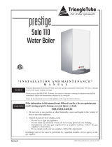
Fig. 1: Sensor Enclosure and Components
Mounting the Outdoor Sensor
1. Remove the front cover and mounting screws /
anchors from the sensor enclosure.
2. When mounting the enclosure, the exterior wall
selected should represent the heat load of the
building. Typically a northern or northeastern
wall will suit most buildings. A southern facing
wall for those buildings, which may have large
glass walls or windows on the southern face.
3. Ensure the sensor enclosure is shielded from
direct sunlight or the effects of heat or cold
from other sources (exhaust fans, appliance
vents...) to prevent false temperature sensing.
4. Mount the sensor enclosure at an elevation on
the exterior wall to prevent accidental damage
or tampering.
5. Avoid mounting the enclosure in areas subject-
ed to excessive moisture.
6. Once an area on the exterior wall has been
determined, to affix the enclosure use the enclo-
sure as a template to mark the location of the
mounting screws.
7. Using a 3/16” drill bit, drill 2 pilot holes on the
marked locations.
8. Tap the enclosed plastic anchors into the pilot
holes. Use care not to damage the anchors.
9. Mount the sensor enclosure using the screws
provided.
Wiring the Sensor
1. Remove the sealing nut and sealing gasket from
the sensor enclosure.
2. Route 18 AWG 2-wire cable or similar wire
cable through the sealing nut and gasket.
Connect the wire ends to the sensor terminals 1
and 2.
2a. Cut a small slit in the seal gasket and route 18
AWG 2-wire cable or similar wire cable
through the seal gasket into the enclosure.
3. Re-insert the sealing gasket and tighten the seal-
ing nut to the sensor enclosure.
4. Route the sensor cable back to the appliance,
ensuring the cable is not route parallel to tele-
phone or power cables.
If the sensor cable is located in an area with
sources of potential electromagnetic interfer-
ence (EMI) the sensor cable should be shield-
ed or the wires should be routed in a ground-
ed metal conduit. If using shielded cable the
shield wire should be connected to the com-
mon ground of the unit.
5. Connect the sensor cable to the outdoor sensor
terminals on the 24V terminal strip located
inside the appliance enclosure (see appliance
wiring diagram).
NOTICE

Outdoor Sensor - PSSENS01
2
The following section applies to PRESTIGE using the Honeywell Type 5 MCBA Control.
This Control is identified as Honeywell MCBA 54201.
NOTICE

Outdoor Sensor - PSSENS01
3
Summer / Winter Switch
If required the CH (Central Heating) system can be
turned off at the appliance, similar to manual sum-
mer / winter switch by press/hold the “+” button
while in
the “StbY” mode, the display will show
“cOFF”. Press/hold the “+” button to turn the CH
system back on, the display will show “c” followed
by CH set point temperature (Parameter 4) or CH
target temperature.
Adjusting Outdoor Reset Curve
Parameters 4, 10, 11, & 12 define the settings of the
outdoor reset curve. See Graph 1 and Table 1, page
5 for an example of modifying the outdoor reset
curve.
CH Maximum Operating Setpoint
(Parameter 4)
If an outdoor temperature sensor is not connected to
the appliance, the appliance setpoint for a heating
call will be set to the CH Maximum Operating
Setpoint. If an outdoor temperature sensor is con-
nected, the CH Maximum Operating Setpoint
becomes the appliance setpoint on the CH Reset
Curve Coldest Day. The outdoor temperature can
be monitored on the appliance display via item 4 of
the INFO menu.
CH Minimum Operating Setpoint
(Parameter 10)
This parameter is not applicable if an outdoor sen-
sor is not connected to the appliance. When an out-
door temperature sensor is connected, the CH
Minimum Operating Setpoint becomes the appli-
ance setpoint on the CH Reset Curve Warmest Day.
CH Reset Curve Coldest Day
(Parameter 11)
This parameter is not applicable if an outdoor sen-
sor is not connected to the appliance. When an out-
door temperature sensor is connected, the CH Reset
Curve Coldest Day is the coldest design tempera-
ture of the heating system.
CH Reset Curve Warmest Day
(Parameter 12)
This parameter is not applicable if an outdoor sen-
sor is not connected to the appliance. When an out-
door temperature sensor is connected, the CH Reset
Curve Warmest Day is the warmest design temper-
ature of the heating system.

Outdoor Sensor - PSSENS01
Entering MCBA Access Code
The installer must enter the MCBA Access Code to
adjust the advanced parameter settings of the
MCBA. The Access Code can be entered as follows:
1. Press the MODE button until the display shows
STbY.
2. Press and hold the MODE and STEP buttons
together for 2 to 3 seconds until the display
shows CODE.
3. Press the STEP button once and the display will
show
C_
XX
where
XX
represents a random
number.
4. Press the “+” or “–“ buttons to change the num-
ber displayed to read C_54.. Press and hold the
“+” or “–“ button to rapidly change the number.
5. When the display reads
C_54, press the STORE
button to save the Access Code. The display
should flash to indicate that the Access Code
was saved.
After the Access Code has been entered, the
advanced parameters can be accessed by pressing
the MODE button until the display shows
PARA.
Once the display shows
PARA, press the STEP but-
ton to reach the appropriate parameter. The display
should follow the following sequence:
Press STEP once-
1140
Press STEP x2 - 2_01
Press STEP x3 - 3_01
Press STEP x4 - 4186
Press STEP x5 - P_10
Press STEP x6 - P_11 Etc......
After Parameter 4, the display will show P followed
by the parameter number. Once a particular para-
meter is reached, the display will change to show
the current setting of that parameter.
The actual parameter values displayed on the
display may vary depending on the application,
but the sequence will always occur in the order
shown.
Changing a Parameter Setting
1. Use the “+” or “–“ button to change the para-
meter setting.
2. Press the STORE button to save the change.
The display should flash to indicate that the
change was saved.
3. Press the RESET button to leave the Access
Code mode.
Parameter 4 is adjustable from 86ºF to
194ºF. The factory setting is 186ºF. Adjusting
this parameter may affect the performance
of the appliance.
• Once Parameter 4 is displayed, use the + or -
button to modify the parameter setting.
• Once the desired parameter setting is reached
press STORE to save the value. The display
will flash once to confirm the data has been
saved.
• To activate the stored parameter value, press
MODE twice to return to the STBY mode.
NOTICE
NOTICE
4

Outdoor Sensor - PSSENS01
5
90
20
60
100
140
180
70
64
50
30
10 0
-10
86
CH (Central Heating) Temperature ( F)
Outdoor Air Temperature ( F)
Parameter 4 Set Point
Parameter 10
Set Point
Parameter 12 Setting
Parameter 11 Setting
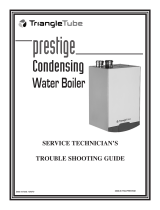
Table 1: Outdoor Air Temperature Reset (Example)
Graph 1: Outdoor Air Temperature Reset Curve (Example)
Graph 1 illustrates Parameter 4 adjusted to 140ºF target temperature at 0ºF outdoor air temperature.
Note: Factory setting of Parameter 4 is 186ºF.

Outdoor Sensor - PSSENS01
6
The following section applies to the CHALLENGER condensing boiler and It’s internal
control module.
NOTICE

Outdoor Sensor - PSSENS01
7
Adjusting Outdoor Reset Curve
The appliance CH set point along with Parameters
5, 6 & 7 define the settings of the outdoor reset
curve. See Graph 2 and Table 2, page 8 for an
example of modifying the outdoor reset curve.
CH (Maximum Operating Temperature)
If an outdoor temperature sensor is not connected to
the appliance, the appliance setpoint for a heating
call will be set to the CH Setpoint. If an outdoor
temperature sensor is connected, the CH Maximum
Appliance Operating Setpoint becomes the appli-
ance setpoint on the CH Reset Curve Coldest Day.
CH Minimum Boiler Operating Setpoint
(Parameter 5)
This parameter is not applicable if an outdoor sen-
sor is not connected to the appliance. When an out-
door temperature sensor is connected, the CH
Minimum Appliance Operating Setpoint becomes
the appliance setpoint on the CH Reset Curve
Warmest Day.
CH Reset Curve Coldest Day
(Parameter 6)
This parameter is not applicable if an outdoor sen-
sor is not connected to the appliance. When an out-
door temperature sensor is connected, the CH Reset
Curve Coldest Day is the coldest design tempera-
ture of the heating system.
CH Reset Curve Warmest Day
(Parameter 7)
This parameter is not applicable if an outdoor sen-
sor is not connected to the appliance. When an out-
door temperature sensor is connected, the CH Reset
Curve Warmest Day is the warmest design temper-
ature of the heating system.
Changing Outdoor Reset Parameters
1. Press the service button until the appropriate
parameter number or or appears in the
operating display.
2. Press the or buttons to set the desired para-
meter value on the main display.
3. Once the desired parameter value has been
entered press reset until a appears on the
operating display.
The appliance control module has now been repro-
grammed with the desired parameter values.
Pressing the ON/OFF button will exit the
parameter setting mode without stroing the
parameter changes.
Pressing the service button for a period
exceeding 5 seconds will reset the parameter
settings to the factory default. The main and
service display will show when this
occurs.
P
NOTICE
F
-
S
E
T
Factory Setting
Minimum
Setting
Maximum
Setting
186ºF 86ºF 194ºF
Factory Setting
M
inimum
Setting
M
aximum
Setting
64ºF 60ºF 78ºF
Factory Setting
Minimum
Setting
Maximum
Setting
00ºF -22ºF 50ºF
Factory Setting
Minimum
Setting
Maximum
Setting
86ºF 60ºF 140ºF

Outdoor Sensor - PSSENS01
8
Revised 7/29/10
2010-21-Prestige Outdoor Sensor
90
20
60
80
100
140
70
64
50
30
10 0
-10
7
7
CH (Central Heating) Temperature ( F)
Outdoor Air Temperature ( F)
CH Set Point
Parameter 5
Set Point
Parameter 7 Setting
Parameter 6 Setting
Graph 2: Outdoor Air Temperature Reset Curve (Example)
Table 2: Outdoor Air Temperature Reset (Example)
Graph 2 illustrates CH Setpoint adjusted to 140ºF target temperature at 0ºF outdoor air temperature.
Note: Factory setting of CH set point is 186ºF
Outdoor CH target Temp.
10ºF or Lower 140ºF
30ºF 117ºF
50ºF 93ºF
64ºF or Higher 77ºF
/