
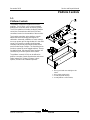
Service and Repair Manual
Serial Number Range
Z
®
-60/37 DC
from Z6016N-101 to
Z6016N-
599
from Z60N-
600
This manual includes:
Repair procedures
Fault Codes
Electrical and
Hydraulic Schematics
Z
®
-60/37 FE
For detailed maintenance
procedures, refer to the
appropriate Maintenance
Manual for your machine.
Part No. 1271125GT
Rev A6
December 2018

Service and Repair Manual December 2018
Introduction
ii Z®-60/37 DC • Z®-60/37 FE Part No. 1271125GT
Intr oducti o n Intr oducti o n
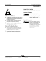
Important
Read, understand and obey the safety rules and
operating instructions in the appropriate Operator's
Manual on your machine before attempting any
procedure.
This manual provides troubleshooting and repair
procedures for qualified service professionals.
Basic mechanical, hydraulic and electrical skills are
required to perform most procedures. However,
several procedures require specialized skills, tools,
lifting equipment and a suitable workshop. In these
instances, we strongly recommend that
maintenance and repair be performed at an
authorized Genie dealer service center.
Compliance
Machine Classification
Group B/Type 3 as defined by ISO 16368
Machine Design Life
Unrestricted with proper operation, inspection and
scheduled maintenance.
Technical Publications
Genie has endeavored to deliver the highest
degree of accuracy possible. However, continuous
improvement of our products is a Genie policy.
Therefore, product specifications are subject to
change without notice.
Readers are encouraged to notify Genie of errors
and send in suggestions for improvement. All
communications will be carefully considered for
future printings of this and all other manuals.
Contact Us:
Internet: www.genielift.com
E-mail: awp.techpub@terex.com
Find a Manual for this Model
Go to http://www.genielift.com
Use the links to locate Service Manuals,
Maintenance Manuals, Service and Repair
Manuals, Parts Manuals and Operator's Manuals.
Copyright © 2016 by Terex Corporation
1271125GT Rev A, April 2016
First Edition, First Printing
Genie and “Z” are registered trademarks of Terex South Dakota,
Inc. in the U.S.A. and many other countries.

December 2018 Service and Repair Manual
Introduction
Part No. 1271125GT Z®-60/37 DC • Z®-60/37 FE iii
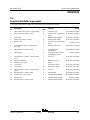
Revision History
Revision
Date
Section
Procedure / Page / Description
A 3/2016
Initial Release
A1 6/2016 Repair Procedures How to Adjust Proportional Relief Valve and Hydraulic
Pressure Sensor / Updated
A2 9/2016 Introduction Serial number Legend
A3 12/2016 Schematic Power Cable Wiring Diagram
A4 11/2017 Specifications Machine Specifications
A5 5/2018 Schematic Corrected Options Schematic
A6 12/2018 Specifications Rotate hub torque value
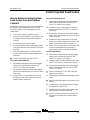
Reference Examples:
Electronic Version
Click on any content o
r procedure in the Table of Contents to view
the update.
Section – Repair Procedure, 4-2
Section – Fault Codes, All charts
Section – Schematics, Legends and schematics

Service and Repair Manual December 2018
Introduction
iv Z®-60/37 DC • Z®-60/37 FE Part No. 1271125GT
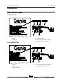
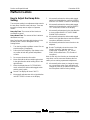
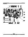
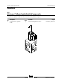
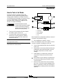
Serial Number Legend
To August 31, 2016
1 Model
2 Model year
3 Facility code
4 Sequence number
5 Serial number (stamped on chassis)
6 Serial label (located under cover)
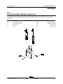
From September 1, 2016
1 Model
2 Facility code
3 Sequence number
4 Serial number (stamped on chassis)
5 Serial label (located under cover)

December 2018 Service and Repair Manual
Safety Rules
Part No. 1271125GT Z®-60/37 DC • Z®-60/37 FE v
Section 1 Safet y R ules
Danger
Failure to obey the instructions and safety rules in
this manual and the appropriate Operator's Manual
on your machine will result in death or serious
injury.
Many of the hazards identified in the operator's
manual are also safety hazards when maintenance
and repair procedures are performed.
Do Not Perform Maintenance
Unless:
R You are trained and qualified to perform
maintenance on this machine.
R You read, understand and obey:
• manufacturer's instructions and safety rules
• employer's safety rules and worksite
regulations
• applicable governmental regulations
R You have the appropriate tools, lifting
equipment and a suitable workshop.

Service and Repair Manual December 2018
Safety Rules
vi Z®-60/37 DC • Z®-60/37 FE Part No. 1271125GT
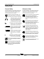
Personal Safety
Any person working on or around a machine must
be aware of all known safety hazards. Personal
safety and the continued safe operation of the
machine should be your top priority.
Read each procedure thoroughly. This
manual and the decals on the machine,
use signal words to identify the following:
Safety alert symbol
—
used to alert
personnel to potential per
sonal
injury hazards. Obey all safety
messages that follow this symbol
to avoid possible injury or death.
Indicates a imminently hazardous
situation which, if not avoided, will
result in death or serious injury.
Indicates a potentially hazardous
situ
ation which, if not avoided,
could result in death or serious
injury.
Indicates a potentially hazardous
situation which, if not avoided,
may cause minor or moderate
injury.
Indicates a potentially hazardous
situation which, if not avoided,
may result
in property damage.
Be sure to wear protective eye wear and
other protective clothing if the situation
warrants it.
Be aware of potential crushing hazards
such as moving parts, free swinging or
unsecured components when lifting or
placing loads. Alw
ays wear approved
steel
-toed shoes.
Workplace Safety
Any person working on or around a machine must
be aware of all known safety hazards. Personal
safety and the continued safe operation of the
machine should be your top priority.
Be sure to keep sparks, flames and lighted
tobacco away from flammable and
combustible materials like battery gases
and engine fuels. Always have an
approved fire extinguisher within easy
reach.
Be sure that all tools and working areas
are properly maintained and ready for
use. Keep work surfaces clean and free of
debris that could get into machine
components and cause damage.
Be sure any forklift, overhead crane or
other lifting or supporting device is fully
capable of supporting and stabilizing the
weight to be lifted.
Use only chains or
straps that are in good condition and of
ample capacity.
Be sure that fasteners intended for one
time use (i.e., cotter pins and self
-locking
nuts) are not reused. These components
may fail if they are used a second time.
Be sure t
o properly dispose of old oil or
other fluids. Use an approved container.
Please be environmentally safe.
Be sure that your workshop or work area
is properly ventilated and well lit.

December 2018
Table of Contents
Part No. 1271125GT Z®-60/37 DC • Z®-60/37 FE vii
Introduction Introduction ........................................................................................................... ii
Important Information ............................................................................................. ii
Find a Manual for this Model .................................................................................. ii
Serial Number Legend .......................................................................................... iv
Section 1 Safety Rules .......................................................................................................... v
General Safety Rules ............................................................................................. v
Section 2 Specifications ....................................................................................................... 1
Machine Specifications ........................................................................................... 1
Performance Specifications .................................................................................... 2
Hydraulic Specification ........................................................................................... 2
Hydraulic Component Specifications...................................................................... 5
Manifold Component Specifications ....................................................................... 6
Kubota D1105 Engine Specifications ..................................................................... 7
Machine Torque Specifications .............................................................................. 8
Machine Component Weights ................................................................................ 8
Hydraulic Hose and Fitting Torque Specifications ................................................. 9
Torque Procedure ................................................................................................ 10

December 2018
Table of Contents
viii Z®-60/37 DC • Z®-60/37 FE Part No. 1271125GT
Section 3 Repair Procedures ............................................................................................. 12
Introduction .......................................................................................................... 12
Cailbration Process Steps .................................................................................... 14
Platform Controls ............................................................................................... 15
1-1 Platform Controls ........................................................................................... 15
How to Adjust the Joystick Threshold Setting ................................................ 16
How to Adjust the Joystick Max-out Setting ................................................... 17
How to Adjust the Joystick Ramp Rate Setting .............................................. 20
1-2 How to Calibrate Booms Angle Sensors ....................................................... 21
1-3 How to Clear the Fault History ....................................................................... 22
Platform Components ....................................................................................... 22
2-1 Platform Leveling Slave Cylinder ................................................................... 22
2-2 Platform Rotator ............................................................................................. 24
2-3 Platform Overload System ............................................................................. 25
2-4 How to Reset Overload Recovery Message .................................................. 27
Jib Boom Components ...................................................................................... 28
3-1 Jib Boom ........................................................................................................ 28
3-2 Jib Boom Lift Cylinder .................................................................................... 29
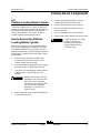
Primary Boom Components ............................................................................. 30
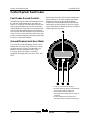
4-1 Cable Track.................................................................................................... 30
How to Repair the Cable Track....................................................................... 31
4-2 Primary Boom ................................................................................................ 31
How to Disassemble the Primary Boom ......................................................... 32
4-3 Primary Boom Lift Cylinder ............................................................................ 33
4-4 Primary Boom Extension Cylinder ................................................................. 34
4-5 Platform Leveling Master Cylinder ................................................................. 35

December 2018
Table of Contents
Part No. 1271125GT Z®-60/37 DC • Z®-60/37 FE ix
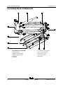
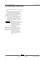
Secondary Boom Components ......................................................................... 36
5-1 Secondary Boom Lift Cylinder ........................................................................ 37
Engines ................................................................................................................ 39
6-1 RPM Adjustment ............................................................................................ 39
How to Replace the Motor Tach Sensor ......................................................... 39
Hydraulic Pumps ................................................................................................ 40
7-1 Function Pump ............................................................................................... 40
How to Check the Function Pump Calibration ................................................ 41
Manifolds ............................................................................................................. 42
8-1 Function Manifold Components ..................................................................... 42
8-2 Valve Adjustments - Function Manifold .......................................................... 47
How to Adjust the Proportional Relief Valve and Hydraulic Pressure Sensor 47
How to Adjust the Platform Level Up Relief Valve .......................................... 48
How to Adjust the Primary Boom Extend Relief Valve.................................... 49
8-3 Jib Boom / Platform Rotate Manifold Components ........................................ 50
8-4 Turntable Rotation Manifold Components ..................................................... 51
8-5 Oscillate Directional Valve Manifold Components ......................................... 52
8-6 How to Set Up the Oscillate Directional Valve ............................................... 53
How to Adjust the Oscillate Reducing Valve ................................................... 53
How to Test a Coil Diode ................................................................................ 55
Turntable Rotation Components ...................................................................... 56
9-1 Turntable Rotation Assembly ......................................................................... 56
9-2 How to Replace the Universal Tilt Sensor ..................................................... 58
How to Calibrate the Universal Tilt Sensor ..................................................... 59
Axle Components ............................................................................................... 60
10-1 Oscillating Axle Cylinders ............................................................................. 60
10-2 How to Remove the Steer Cylinder .............................................................. 61
How to Calibrate the Steer Angle Sensor ....................................................... 61

December 2018
Table of Contents
x Z®-60/37 DC • Z®-60/37 FE Part No. 1271125GT
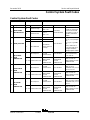
Section 4 Fault Codes ......................................................................................................... 63
Introduction .......................................................................................................... 63
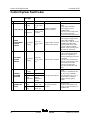
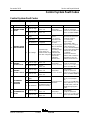
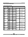
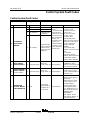
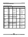
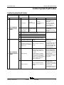
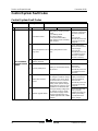
Control System Fault Codes ............................................................................. 64
Fault Codes Ground Controls .............................................................................. 64
How to Retrieve Control System Fault Codes - Platform Controls ...................... 65
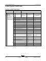
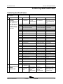
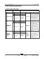
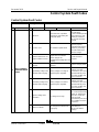
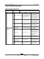
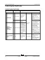
Control System Fault Codes ................................................................................ 66
Section 5 Navigation Menus .............................................................................................. 81
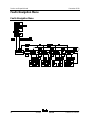
Faults Navigation Menu ....................................................................................... 82
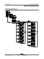
Options Navigation Menu ..................................................................................... 83
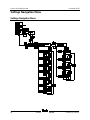
Settings Navigation Menu .................................................................................... 84
Section 6 Schematics ......................................................................................................... 85
Introduction .......................................................................................................... 85
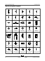
Electrical Symbol Legend .................................................................................... 86
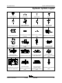
Hydraulic Symbols Legend .................................................................................. 87
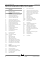
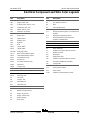
Electrical Component and Wire Color Legends ................................................... 88
Kubota Engine Fuse and Relay Module .............................................................. 91
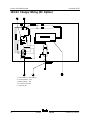
12V DC Charger Wiring (DC Option) ................................................................... 92
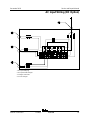
AC Input Wiring (DC Option) ................................................................................ 93
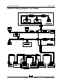
CAN BUS Wiring Diagram - DC Models .............................................................. 94
Limit Switch/Angle Sensor Legend ...................................................................... 95
Electrical Schematics – Options ...................................................................... 97
Wiring Diagram - Options .................................................................................... 98
Schematics - Options, 4WD, DC, and FE Models ............................................... 99
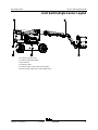
Power Cable Wiring Diagram ............................................................................. 102
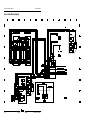
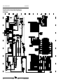
Hydraulic Schematics ...................................................................................... 103
Hydraulic Schematic - DC and FE Models ........................................................ 104
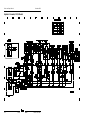
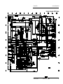
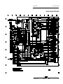
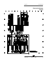
Electrical Schematics ...................................................................................... 105
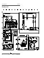
Electrical Schematics, DC/FE Models ............................................................... 106
Ground Control Box Terminal Strip Wiring Diagram .......................................... 112
Platform Control Box Wiring Diagram ................................................................ 113

December 2018 Service and Repair Manual
Specifications
Part No. 1271125GT Z®-60/37 DC • Z®-60/37 FE 1
Section 2 Speci fic ations
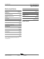
Machine Specifications
Tires and wheels
Rough terrain
Tire size
(Rough terrain)
355/55D625
Tire weight, foam
-filled
(minimum) (Rough terrain)
426 l
bs
193 k
g
Tire weight, foam
-filled
(minimum) (Rou
gh terrain non
marking)
426 l
bs
193 k
g
Tire ply rating
14
Wheel lugs
9 @ 5/8 -
18
Lug nut torque, dry
240 ft-
lbs
325 Nm
Lug nut torque, lubricated
180 ft-
lbs
244 Nm
Overall tire diameter
(Rough terrain, low profile tires)
36.9 i
n
93.7 c
m
Fluid capacities
Fuel tank
17 g
allons
64.4 liters
Hydraulic tank
18 g
allons
68 l
iters
Hydraulic system
(including tank)
21 g
allons
80 l
iters
Drive hubs
24 f
l oz
710 c
c
Turntable rotation drive hub
43
fl oz
1262
cc
Drive hub oil type:
SAE 9
0 multipurpose hypoid gear oil API service
classification GL5
Batteries
Type
L16G-
AC lead acid
AGM dry cell
Group
903-
L16
Quantity
8
Capacity (lead acid)
(dry cell)
390 AH
415 AH
Reserve capacity @ 25A rate
789 m
inutes
885 m
inutes
Weight
Refer to
Machine
Compone
nt Weights
For operational specifications, refer to the
Operator's Manual.

Service and Repair Manual December 2018
Specifications
2 Z®-60/37 DC • Z®-60/37 FE Part No. 1271125GT
Performance Specifications
Drive speed, maximum
stowed position
2WD/4WD models Stowed
4.0 m
ph
6.44 k
m/h
40 ft / 6.8 s
ec
12.2 m / 6.8 s
ec
Elevated
0.7 m
ph
1.0 k
m/h
40 ft / 40 s
ec
12.2 m / 40 s
ec
Gradeability
See Operator's Manual
Braking distance
High range on paved surface
3 to 6 f
eet
0.9 to 1.8
m
Function speeds, maximum from platform controls
Jib boom up
13 to 17 s
econds
Jib boom down
13 to 17 s
econds
Primary boom up
54 to 66 s
econds
Primary boom down
54 to 66 s
econds
Primary boom extend
40 to 50 s
econds
Primary boom retract
31 to 39 s
econds
Secondary boom up
31 to 39 s
econds
Secondary boom down
31 to 39 s
econds
Turntable rotate, per 9
0°
Stowed
21 to 27 s
econds
Turntable rotate, per 90°
Not stowed
35 to 42 s
econds
For operational specifications, refer to the
Operator's Manual.
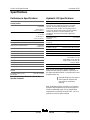
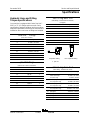
Hydraulic Oil Specifications
Hydraulic Fluid Specifications
Genie specifications re
quire hydraulic oils which are
designed to give maximum protection to hydraulic
systems, have the ability to perform over a wide
temperature range, and the viscosity index should
exceed 140. They should provide excellent antiwear,
oxidation prevention, cor
rosion inhibition, seal
conditioning, and foam and aeration suppression
properties.
Cleanliness level,
minimum
ISO 15/13
Water content,
maximum
250 p
pm
Recommended Hydraulic Fluid
Hydraulic oil type
Chevron Rando HD Premium
Viscosity grade
32
Viscosi
ty index
200
Optional Hydraulic Fluids
Mineral based
Shell Tellus S2 V 32
Shell Tellus S2 V 46
Shell Tellus S4 VX 32 Shell
Shell Donax TG (Dexron III)
Chevron 5606A
Biodegradable
Petro Canada Environ MV
46
Fire resistant
UCON Hydrolube HP-
5046
Note: Genie specifications require additional
equipment and special installation instructions for
the approved optional fluids. Consult Genie Product
Support before use.
Optional fluids may not have the
same hydraulic lifespan and
may result in component
damag
e.
Note: Extended machine operation can cause the
hydraulic fluid temperature to increase beyond it's
maximum allowable range. If the hydraulic fluid
temperature consistently exceeds 200°F / 90°C an
optional oil cooler may be required.

December 2018 Service and Repair Manual
Specifications
Part No. 1271125GT Z®-60/37 DC • Z®-60/37 FE 3
Do not top off with incompatible
hydraulic fluids. Hydraulic fluids
may be incompatible due to the
differences in base additive
chemistry. When incompatible
fluids are mixed, insoluble
materials may form and deposit
in the hydraulic system,
plugging hydraulic lines, filte
rs,
control valves and may result in
component damage.
Note: Do not operate the machine when the
ambient air temperature is consistently above
120°F / 49°C.
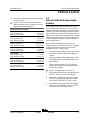
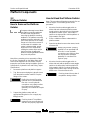
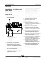
Hydraulic Fluid Temperature
Range
Ambient air temperature
1 Chevron hydraulic oil 5606A
2 Petro-Canada Environ MV 46
3 UCON Hydrolube HP-5046D
4 Chevron Rando HD premium oil MV
Chevron Rando HD Premium Oil
MV Fluid Properties
ISO Grade
32
Viscosity index
200
Kinematic Viscosity
cSt @ 200°F / 100°C
cSt @ 104°F / 40°C
7.5
33.5
Brookfield Viscosity
cP @
-4°F / -20°C
cP @
-22°F / -30°C
1040
3310
Flash point
375°F / 190°C
Pour point
-58°F / -
50°C
Maximum continuous operating
temperature
171°F / 77°C
Note: A hydraulic oil heating system is
recommended when the ambient temperature is
consistently below 0°F / -18°C.
Note: Do not operate the machine when the
ambient temperature is below -20°F / -29°C with
Rando HD Premium MV.

Service and Repair Manual December 2018
Specifications
4 Z®-60/37 DC • Z®-60/37 FE Part No. 1271125GT
Chevron 5606A Hydraulic Oil
Fluid Properties
ISO Grade
15
Viscosity index
300
Kinematic Viscosity
cSt @ 200°F / 100°C
cSt @ 104°
F / 40°C
cSt @
-40°F / -40°C
5.5
15.0
510
Flash point
180°F / 82°C
Pour point
-81°F / -
63°C
Maximum continuous operating
temperature
124°F / 51°C
Note: Use of Chevron 5606A hydraulic fluid, or
equivalent, is required when ambient temperatures
are consistently below 0°F / -17°C unless an oil
heating system is used.
Continued use of Chevron
5606A hydraulic fluid, or
equivalent, when ambient
temperatures are consistently
above 32°F / 0°C may result in
component damage
Petro-Canada Environ MV 46
Fluid Properties
ISO Grade
46
Viscosity index
154
Kinematic Viscosity
cSt @ 200°F / 100°C
cSt @ 104°F / 40°C
8.0
44.4
Flash point
482°F / 250°C
Pour point
-49°F / -
45°C
Maximum continuous operating
temperature
180°F / 82°C
Shell Tellus S4 VX Fluid
Properties
ISO Grade
32
Viscosity index
300
Kinematic Viscosity
cSt @ 200°F / 100°C
cSt @ 104°F / 40°C
9
33.8
Brookfield Viscosity
cSt @
-4°F / -20°C
cSt @
-13°F / -25°C
cSt @
-40°F / -40°C
481
702.4
2624
Flash point
>100
Pour point
-76°F / -
60°C
Maxi
mum continuous operating
temperature
103°F / 75°C

December 2018 Service and Repair Manual
Specifications
Part No. 1271125GT Z®-60/37 DC • Z®-60/37 FE 5
UCON Hydrolube HP-5046 Fluid
Properties
ISO Grade
46
Viscosity index
192
Kinematic Viscosity
cSt @ 149°F / 65°C
cSt @ 104°F / 40°C
cSt @ 0°F /
-18°C
22
46
1300
Flash point
None
Pour point
-81°F / -
63°C
Maximum continuous operating
temperature
189°F / 87°C
Hydraulic Component
Specifications
Function pump
Type
2
s
ection tandem gear
pump
Displacement per revolution
(inner pump)
(outer pump)
.40 cu in / 6.6 c
c
.20 cu in / 3.3 c
c
Max flow rate
L/min(inner pump)
L/min(outer pump)
6.8 g
pm / 25.74
3.4 g
pm / 12.87
Auxiliary Pump
Type
Fixed displacement
gear pump
Displacement per revolution
1.7 g
pm
6.44 L/min
Function manifold
Proportional relief valve pressure,
variable
50 to 3000 p
si
3.4 to 207 b
ar
Platform level relief valve
pressure
2800 p
si
193 b
ar
Primary boom extend relief valve
pressure
1250 p
si
86 b
ar
Oscillate reducing valve pressure
400 p
si
28 b
ar
Platform level flow regulator
Variable
1 to 1.5 g
pm
3.8 t
o 5.7 L/min
Hydraulic Filters
High pressure filter:
Beta 5 ˆ 1000
Hydraulic tank return filter
Beta 10 ˆ 200

Service and Repair Manual December 2018
Specifications
6 Z®-60/37 DC • Z®-60/37 FE Part No. 1271125GT
Manifold Component
Specifications
Plug torque
SAE No. 4
13 ft-
lbs / 18 Nm
SAE No. 6
18 ft-
lbs / 24 Nm
SAE No. 8
50 ft-
lbs / 68 Nm
SAE No.10
55 ft-
lbs / 75 Nm
SAE No. 12
56 ft-
lbs / 75.9 Nm
Valve Coil Resistance
Note: The following coil resistance specifications are at
an ambient temperature of 68°F / 20°C. As valve coil
resistance is sensitive to changes in air temperature, the
coil resistance will typically increase or decrease by 4%
for each 18°F / 10°C that your air temperature increases
or decreases from 68°F / 20°C.
Description
Specification
Proportional solenoid relief valve, 24V D
C
(schematic item AA)
22
Ω
Proportional solenoid valve,
3 position
4
way, 20V DC (schematic items B, G,
and S
19
Ω
Proportional solenoid valve,
3 position
4
way, 20V DC (schematic items AE, E, I,
O, R, and Z)
24
Ω
Solenoid valve,
2 position 3way, 12V DC
(schematic item JA)
9
Ω

December 2018 Service and Repair Manual
Specifications
Part No. 1271125GT Z®-60/37 DC • Z®-60/37 FE 7
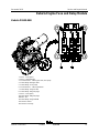
Kubota D1105 Engine
Displacement
68.53 c
u in
1.123 liters
Number of cylinders
3
Bore and Stroke
3.07 x 3.09 i
nches
78 x 78.4 m
m
Horsepower, gross
intermittent
24.8 @ 3000 r
pm
18.5 kW @ 3000 r
pm
Combustion system
Indirect injection
Firing order
1 - 2 -
3
Low idle
2150 r
pm
208 Hz
High idle
3000 r
pm
500 Hz
Compression ratio
24:1
Compression pressure
412 to 469 p
si
28.4 to 32.3 b
ar
Governor
mechanical
Valve Clearance, cold
0.0014 to 0.0025 i
n
0.145 to 0.185 m
m
Lubrication system
Oil pressure
28 to 64 p
si
1.9 to 4.4 b
ar
Oil capacity
(including filter)
5.4 q
uarts
5.1 liters
Oil viscosity requirements
Below
-10°C (14° F) SAE 10W-
30
-
10 to 25° C (14° to 77° F) SAE 10W-
30/
SAE 15W-
40
Above 25° C (77° F)
SAE30, SAE10W
-
30/
SAE15W-
40
Unit ships with 15W
-40. Extreme operating
temperatures may require the use of alternative engine
oils. For oil requirements, refer to the Engine Operator
Manual for your engine.
Engine coolant
Capacity
3.3 q
uarts
3.1 liters
Fuel injection system
Injection pump make
Bosch MD
Injection pump pressure,
maximum
1991 p
si
137 b
ar
Injection timing
18° BTDC
Fuel requirement
For fuel requirements, refer to the engine Operator
Manual for your engine.
St
arter motor
Cranking speed
200 -
300 RPM
Current draw, normal load
155A
Battery
Type
12V DC
Group
70
Quantity
1
Ampere hour
75AH
Cold cranking ampere
450A
Reserve capacity @ 25A rate
70 m
inutes
Alternator output
40A @ 12V DC
Fan belt deflection
1/4 to 3/8 i
nch
7 to 9 m
m
Electric clutch
1.6A @ 48 V DC
29.22 Ω +/-
5%

Service and Repair Manual December 2018
Specifications
8 Z®-60/37 DC • Z®-60/37 FE Part No. 1271125GT
Machine Torque Specifications
Platform rotator
1
-8 center bolt, GR 5
Lubricated
480 ft-
lbs
650 Nm
Dry
640 ft-
lbs
867 Nm
3/8
-16 bolts, GR 8
Lubricated
33 ft-
lbs
45 Nm
Dry
44 ft-
lbs
60 Nm
Turntable rotate
assembly
Rotate bearing mounting bolts, lubricated
160 ft-
lbs
217 Nm
Rotate
drive hub mounting bolts, lubricated
80 ft-
lbs
108.4 Nm
Drive motor and hubs
Drive hub mounting bolts, dry
93 ft-
lbs
126 Nm
Drive motor leads square nuts (requires
1
2 point socket)
9 f
t lbs
12 Nm
Machine Component Weights
Tire and wheel assembly
429 l
bs
195 k
g
Drive motor and hub
160 l
bs
73 k
g
Engine assembly
724 l
bs
328 k
g
Primary boom
1277 l
bs
579 k
g
Primary boom cylinder
272 l
bs
123 k
g
Primary boom extend cylinder
234 l
bs
106 k
g
Secondary boom linkage 3017 l
bs
1368 k
g
Secondary boom cylinder
180 l
bs
82 k
g
Jib boom assembly
247lbs
112kg
Jib boom cylinder
47 l
bs
22 k
g
Oscillate cy
linder 50 l
bs
23 k
g
6
ft / 1.8 m platform 275 l
bs
125 k
g
8
ft / 2.4 m platform 315 l
bs
143 k
g
Battery box assembly with counterweight
(without batteries)
612 l
bs
278 k
g
Battery 6volt (wet)
106 l
bs
48 k
g
Battery
6 volt (maintenance free) 123 l
bs
56 k
g

December 2018 Service and Repair Manual
Specifications
Part No. 1271125GT Z®-60/37 DC • Z®-60/37 FE 9
Hydraulic Hose and Fitting
Torque Specifications
Your machine is equipped with Parker Seal-Lok™
ORFS or 37° JIC fittings and hose ends. Genie
specifications require that fittings and hose ends be
torqued to specification when they are removed and
installed or when new hoses or fittings are installed.
Seal-Lok™ Fittings
(hose end - ORFS)
SAE Dash Size Torque
-4 10 ft-lbs / 13.6 Nm
-6 30 ft-lbs / 40.7 Nm
-8 40 ft-lbs / 54.2 Nm
-10 60 ft-lbs / 81.3 Nm
-12 85 ft-lbs / 115 Nm
-16 110 ft-lbs / 150 Nm
-20 140 ft-lbs / 190 Nm
-24 180 ft-lbs / 245 Nm
JIC 37° Fittings
(swivel nut or hose connection)
SAE Dash Size Thread Size Flats
-4 7/16-20 2
-6 9/16-18 1 ¼
-8 3/4-16 1
-10 7/8-14 1
-12 1 1/16-12 1
-16 1 5/16-12 1
-20 1 5/8-12 1
-24 1 7/8-12 1
SAE O-ring Boss Port
(tube fitting - installed into Aluminum)
(all types)
SAE Dash Size Torque
-4 14 ft-lbs / 19 Nm
-6 23 ft-lbs / 31.2 Nm
-8 36 ft-lbs / 54.2 Nm
-10 62 ft-lbs / 84 Nm
-12 84 ft-lbs / 114 Nm
-16 125 ft-lbs / 169.5 Nm
-20 151 ft-lbs / 204.7 Nm
-24 184 ft-lbs / 249.5 Nm
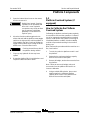
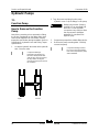
Adjustable Fitting Non-adjustable fitting
1 jam nut
SAE O-ring Boss Port
(tube fitting - installed into Steel)
SAE Dash Size
Torque
-4 ORFS / 37° (Adj)
ORFS (Non-adj)
37° (Non-adj)
15 ft-lbs / 20.3 Nm
26 ft-lbs / 35.3 Nm
22 ft-lbs / 30 Nm
-6 ORFS (Adj / Non-adj)
37° (Adj / Non-adj)
35 ft-lbs / 47.5 Nm
29 ft-lbs / 39.3 Nm
-8 ORFS (Adj / Non-adj)
37° (Adj / Non-adj)
60 ft-lbs / 81.3 Nm
52 ft-lbs / 70.5 Nm
-10 ORFS (Adj / Non-adj)
37° (Adj / Non-adj)
100 ft-lbs / 135.6 Nm
85 ft-lbs / 115.3 Nm
-12 (All types) 135 ft-lbs / 183 Nm
-16 (All types) 200 ft-lbs / 271.2 Nm
-20 (All types) 250 ft-lbs / 339 Nm
-24 (All types) 305 ft-lbs / 413.5 Nm

Service and Repair Manual December 2018
Specifications
10 Z®-60/37 DC • Z®-60/37 FE Part No. 1271125GT
Torque Procedure
Seal-Lok™ fittings
1 Replace the O-ring. The O-ring must be
replaced anytime the seal has been broken.
The O-ring cannot be re-used if the fitting or
hose end has been tightened beyond finger
tight.
Note: The O-ring in Parker Seal Lok™ fittings and
hose end are custom-size O-rings. They are not
standard size O-rings. They are available in the
O-ring field service kit (Genie part number 49612).
2 Lubricate the O-ring before installation.
3 Be sure the O-ring face seal is seated and
retained properly.
4 Position the tube and nut squarely on the face
seal end of the fitting, and tighten the nut finger
tight.
5 Tighten the nut or fitting to the appropriate
torque. Refer to the appropriate torque chart in
this section.
6 Operate all machine functions and inspect the
hose, fittings and related components to
confirm there are no leaks.
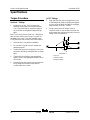
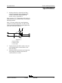
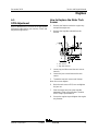
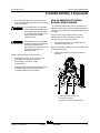
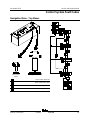
JIC 37° fittings
1 Align the tube flare (hex nut) against the nose
of the fitting body (body hex fitting) and tighten
the hex nut to the body hex fitting to hand tight,
approximately 30 in-lbs / 3.4 Nm.
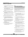
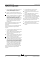
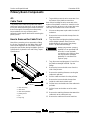
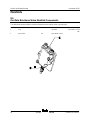
2 Using a permanent ink marker, make a
reference mark on one the flats of the hex nut
and continue the mark onto the body of the hex
fitting. Refer to Illustration 1.
Illustration 1
1 hex nut
2 reference mark
3 body hex fitting
Page is loading ...
Page is loading ...
Page is loading ...
Page is loading ...
Page is loading ...
Page is loading ...
Page is loading ...
Page is loading ...
Page is loading ...
Page is loading ...
Page is loading ...
Page is loading ...
Page is loading ...
Page is loading ...
Page is loading ...
Page is loading ...
Page is loading ...
Page is loading ...
Page is loading ...
Page is loading ...
Page is loading ...
Page is loading ...
Page is loading ...
Page is loading ...
Page is loading ...
Page is loading ...
Page is loading ...
Page is loading ...
Page is loading ...
Page is loading ...
Page is loading ...
Page is loading ...
Page is loading ...
Page is loading ...
Page is loading ...
Page is loading ...
Page is loading ...
Page is loading ...
Page is loading ...
Page is loading ...
Page is loading ...
Page is loading ...
Page is loading ...
Page is loading ...
Page is loading ...
Page is loading ...
Page is loading ...
Page is loading ...
Page is loading ...
Page is loading ...
Page is loading ...
Page is loading ...
Page is loading ...
Page is loading ...
Page is loading ...
Page is loading ...
Page is loading ...
Page is loading ...
Page is loading ...
Page is loading ...
Page is loading ...
Page is loading ...
Page is loading ...
Page is loading ...
Page is loading ...
Page is loading ...
Page is loading ...
Page is loading ...
Page is loading ...
Page is loading ...
Page is loading ...
Page is loading ...
Page is loading ...
Page is loading ...
Page is loading ...
Page is loading ...
Page is loading ...
Page is loading ...
Page is loading ...
Page is loading ...
Page is loading ...
Page is loading ...
Page is loading ...
Page is loading ...
Page is loading ...
Page is loading ...
Page is loading ...
Page is loading ...
Page is loading ...
Page is loading ...
Page is loading ...
Page is loading ...
Page is loading ...
Page is loading ...
Page is loading ...
Page is loading ...
Page is loading ...
Page is loading ...
Page is loading ...
Page is loading ...
Page is loading ...
Page is loading ...
Page is loading ...
Page is loading ...
Page is loading ...
-
 1
1
-
 2
2
-
 3
3
-
 4
4
-
 5
5
-
 6
6
-
 7
7
-
 8
8
-
 9
9
-
 10
10
-
 11
11
-
 12
12
-
 13
13
-
 14
14
-
 15
15
-
 16
16
-
 17
17
-
 18
18
-
 19
19
-
 20
20
-
 21
21
-
 22
22
-
 23
23
-
 24
24
-
 25
25
-
 26
26
-
 27
27
-
 28
28
-
 29
29
-
 30
30
-
 31
31
-
 32
32
-
 33
33
-
 34
34
-
 35
35
-
 36
36
-
 37
37
-
 38
38
-
 39
39
-
 40
40
-
 41
41
-
 42
42
-
 43
43
-
 44
44
-
 45
45
-
 46
46
-
 47
47
-
 48
48
-
 49
49
-
 50
50
-
 51
51
-
 52
52
-
 53
53
-
 54
54
-
 55
55
-
 56
56
-
 57
57
-
 58
58
-
 59
59
-
 60
60
-
 61
61
-
 62
62
-
 63
63
-
 64
64
-
 65
65
-
 66
66
-
 67
67
-
 68
68
-
 69
69
-
 70
70
-
 71
71
-
 72
72
-
 73
73
-
 74
74
-
 75
75
-
 76
76
-
 77
77
-
 78
78
-
 79
79
-
 80
80
-
 81
81
-
 82
82
-
 83
83
-
 84
84
-
 85
85
-
 86
86
-
 87
87
-
 88
88
-
 89
89
-
 90
90
-
 91
91
-
 92
92
-
 93
93
-
 94
94
-
 95
95
-
 96
96
-
 97
97
-
 98
98
-
 99
99
-
 100
100
-
 101
101
-
 102
102
-
 103
103
-
 104
104
-
 105
105
-
 106
106
-
 107
107
-
 108
108
-
 109
109
-
 110
110
-
 111
111
-
 112
112
-
 113
113
-
 114
114
-
 115
115
-
 116
116
-
 117
117
-
 118
118
-
 119
119
-
 120
120
-
 121
121
-
 122
122
-
 123
123
-
 124
124
-
 125
125


Terex Genie Z-60/37 DC Service and Repair Manual
- Type
- Service and Repair Manual
- This manual is also suitable for
Ask a question and I''ll find the answer in the document
Finding information in a document is now easier with AI
Related papers
-
Terex Genie Z-33/18 Service and Repair Manual
-
-
-
-
-
-
-
-
-
Other documents
-
Genie Z45/25J Bi-Energy Service and Repair Manual
-
-
Victron energy Blue Power 12/6 ; 12/15 ; 24/3 ; 24/8 Owner's manual
-
-
-
Vestil EHN-60-T Owner's manual
-
-
-
Genie S-40 TRAX User manual
-