12
Chapter 4: Dashboard TabEdgeRouter
™
Lite User Guide
Ubiquiti Networks, Inc.
A table displays the following information about each
interface. Click a column heading to sort by that heading.
Description The keywords you entered to describe the
interface are displayed.
Interface The name of the interface is displayed.
Type The type of interface is displayed.
IP Addr The IP address of the interface is displayed.
MTU The MTU (Maximum Transmission Unit) value of the
interface is displayed. This is the maximum packet size (in
bytes) that the interface can transmit.
TX The transmit speed of the interface is displayed.
RX The receive speed of the interface is displayed.
Status The connection status of the interface is displayed.
Actions Click the Actions button to access the following
options:
• Config To configure the interface, click Config. Go to
the Configure the Interface section.
• Disable Disable the interface while keeping its
configuration.
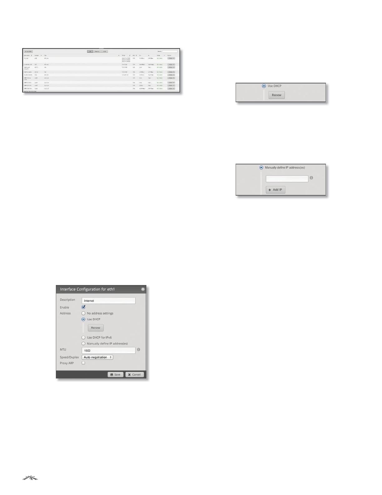
Configure the Interface
After you click Config, the Interface Configuration screen
appears.
Make changes as needed.
• Description Enter keywords to describe this interface.
• Enable Check the box to enable the interface. All of
the interfaces are saved in the system configuration file;
however, only the enabled interfaces are active on the
device.
• Address Select one of the following:
- No address settings The interface uses no address
settings. (In most cases, an address is needed.)
- Use DHCP The interface acquires network settings
from a DHCPv4 server. Click the Renew button to
acquire fresh network settings.
- Use DHCP for IPv6 The interface acquires network
settings from a DHCPv6 server.
- Manually define IP address(es) Enter the
static IP address (example: 192.0.2.1/24 for IPv4
or 2001:db8::1/32 for IPv6). Click Add IP to enter
additional IP addresses.
• MTU Enter the MTU (Maximum Transmission Unit)
value, which is the maximum packet size (in bytes) that a
network interface can transmit. The default is 1500.
• Speed/Duplex The default is Auto negotiation. The
EdgeRouter automatically negotiates transmission
parameters, such as speed and duplex, with its
counterpart. In this process, the networked devices
first share their capabilities and then choose the fastest
transmission mode they both supoprt.
To manually specify the transmission link speed and
duplex mode, select one of the following options:
100/full, 100/half, 10/full, or 10/half.
Full-duplex mode allows communication in both
directions simultaneously. Half-duplex mode
allows communication in both directions, but not
simultaneously and only in one direction at a time.
• Proxy ARP Enable the EdgeRouter to answer a source
host’s ARP (Address Resolution Protocol) requests for
the IP address of a destination host that is not located
on the source host’s network. ARP allows hosts on the
same network to discover each other’s IP address via a
layer 2 broadcast to all MAC addresses. If they are not on
the same network, the layer 2 broadcast will not reach
its destination; however, the EdgeRouter can serve as
the go-between if Proxy ARP is enabled.
Click Save to apply your changes, or click Cancel.


