Page is loading ...

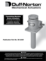
This manual contains important information for the correct installation, operation and maintenance of the equipment
described herein. All persons involved in such installation, operation, and maintenance should be thoroughly familiar with
the contents. To safeguard against the possibility of personal injury or property damage, follow the recommendations and
instructions of this manual and keep it for further reference.
CAUTION!
WARNING!
The equipment shown in this manual is intended for industrial use only and should not be used to lift, support, or otherwise
transport people.

SECTION I
SECTION II
SECTION III
SECTION IV
SECTION V
INTRODUCTION
1-1. General 3
1-2. Applications 3
1-3. Important Precautions 3
1-4. Warranty and Warranty Repair 3
INSTALLATION
2-1. Inspection 4
2-2. Trunnion Mounting 4
2-3. Clevis Pins 4
2-4. Orientation 4
2-5. Vent Plugs 4
2-6. Wiring 5
2-7. Limit Switch Adjustment 5
LUBRICATION
3-1. Screw and Load Bearings 6
3-2. Gearbox Lubrication 6
3-3. Motor Bearings 6
3-4. Clevis and Trunnion Pins 6
MAINTENANCE
4-1. Disassembly 7
4-2. Screw and Tube Disassembly 7
4-3. Screw Removal 7
4-4. Screw and Nut Inspection 7
4-5. Ball Nut Removal 7
4-6. Cleaning 8
4-7. Inspection 8
4-8. Assembly 8
ILLUSTRATED PARTS LIST
5-1. Part Identification 9
FIGURE 5-1. Exploded Parts Illustration 9
TABLE OF CONTENTS
PAGE

1-4. Warranty and Warranty Repair
Subject to the conditions stated herein, Duff-
Norton will repair or replace, without charge, any
parts proven to Duff-Norton’s satisfaction to have
been defective in material or workmanship. Claims
must be made within one year after date of
shipment. Duff-Norton will not repair or replace any
parts that become inoperative because of improper
maintenance, eccentric loading, overloading,
chemical or abrasive action, excessive wear, or
other abuse.
Equipment and accessories not of Duff-Norton's
manufacture are warranted only to the extent that
they are warranted by the manufacturer, and only if
the claimed defect arose during normal use,
applications and service. Equipment which has
been altered or modified by anyone without Duff-
Norton's authorization is not warranted by Duff-
Norton. EXCEPT AS STATED HEREIN, DUFF-
NORTON MAKES NO OTHER WARRANTIES,
EXPRESS OR IMPLIED, INCLUDING WARRANTIES
OF MERCHANTABILITY AND FITNESS FOR A
PARTICULAR PURPOSE.
If you have any questions concerning warranty
repair, please contact Duff-Norton.
Authorization for return must be received from
Duff-Norton before returning any equipment for
inspection or warranty repair.
1-1. General
This manual contains installation and maintenance
instructions for Duff-Norton SCN Series
SuperCylinders. It may be supplemented by
individual instructions for the motor, brake, or gear
reducer used as part of the SuperCylinder. To
ensure satisfactory service, read and understand
the information in this and any accompanying
literature.
1-2. Applications
1-3. Important Precautions
In order to ensure that Duff-Norton acutators
provide good service over a period of years the
following precautions should be taken:
SECTION I
INTRODUCTION
3
(Industrial Use Only) The linear actuators
described and illustrated in this manual are
intended for industrial use only and should
not be used to lift, support or otherwise
transport people unless you have a written
statement from Duff-Norton which
authorizes the specific actuator unit, as
used in your application, as suitable for
moving people.
Do not use actuators with standard motors
in areas containing flammable vapors,
liquids, gases or combustible dusts or
fibers. Refer to Article 500 of The National
Electric Code. Do not use in highly
corrosive or wet environments. Do not use
in applications involving extended exposure
to temperatures below -20˚F or above
140˚F.
The actuator rod clevis must be restrained
from rotating. The amount of restraining
torque is a function of screw geometry and
load. Consult Duff-Norton for expected
values.
1.
2.
3.
jamming. In applications where
overloading is a possibility, appropriate
electronic or mechanical devices should
be incorporated to prevent operation of the
actuator if overloaded.
Do not install an electric motor on a
SuperCylinder with horsepower rating
greater than that shown in the
SuperCylinder catalog.
SuperCylinders are normally supplied
without controls. The installer must
provide adequate electrical controls that
provide motor thermal protection and
incorporate limit switches to ensure that
the actuator is not jammed against internal
or external stops.
SuperCylinders do not incorporate any
protection against mechanical overloading,
either externally applied or through internal
1.
3.
2.
Do not allow actuator to go
beyond specified (catalog) closed
height, or serious damage to
internal mechanism may result.
CAUTION

The Duff-Norton SuperCylinder can be used in an
unlimited number of positions and applications.
Consequently, installation procedures will vary
depending on the environment.
2-1. Inspection
Check the SuperCylinder for any shipping damage.
Be sure that motor fan does not rub fan shroud.
Look for any attached hardware or instructions.
2-2. Trunnion Mounting
Actuator trunnion pins are designed to fit standard
dimension radial spherical plain bearings
(Torrington type SF, or SKF type GEZ, for example).
It is strongly recommended that trunnion pins be
supported by some type of self-aligning bearing, as
perfect alignment of trunnion support bearings is
difficult to achieve. Standard pillow blocks are not
recommended, as their maximum static load rating
is usually less than that of the SuperCylinder. In
addition, most pillow blocks use cast gray iron
frames which are subject to fracture under heavy
loads. Duff-Norton offers Trunnion Blocks to
facilitate the installation of SCN Series
SuperCylinders. These blocks are solid steel and
house a properly sized spherical plain bearing. The
blocks are drilled for mounting either as a
conventional pillow block or as a flange unit. Heat
treated fasteners should be used for all
attachments.
Order mounting blocks per the following chart:
2-3. Clevis Pins
The SuperCylinder should be attached with a steel
clevis pin that is a close fit in the clevis hole. Duff-
Norton recommends the use of pins with hardness
of at least Rockwell C-28. Socket head cap screws
or SAE grade 8 screws may be used, if their length
is such that the threaded portion is not placed in
shear. Use of an anti-seize compound or extreme
pressure grease on the clevis pin will reduce wear
and possible noise. For extreme service, mount
the clevis pin on outboard bearings.
2-4. Orientation
SECTION II
INSTALLATION
4
NZ03, NL03, NU03 Part No. NZ03-510
NZ06, NL06, NU06 Part No. NZ06-510
NZ12, NL12, NU12 Part No. NZ12-510
NZ25, NL25, NU25 Part No. NZ25-510
SuperCylinder series Mounting Blocks (2 req’d)
The application will usually dictate the
orientation of the SuperCylinder. In
applications exposed to dripping water or
dirt, pointing the tube down to reduce the
entry of foreign material is preferred.
The SuperCylinder motor can be rotated
90˚ to change the terminal box location. On
actuators with close coupled motors, the
gasketed face of the motor retains gearbox
oil. Support the actuator with the motor
pointing straight up before loosening close
coupled motors, to avoid loss of gearbox
oil.
Several different limit switch mountings are
utilized, depending on model. If optional
flange holes are apparent, the limit switch
may be repositioned by rotating.
Factory orientation of the outer tube grease
fitting and vent plug is random (tube is
screwed down tight). Plugs may be moved
to an alternate set of holes at 90˚ if
required.
1.
1.
2.
3.
2.
3.
4.
Gearbox venting: The gearbox has three
pipe plugs at various locations. (Note:
models NZ03, NL03, and NL06 use
unvented gearboxes). Two plugs are solid.
The third plug is brass colored and
contains a spring loaded pressure relief
valve for venting built-up pressure. The
pressure relief plug must always be the
highest plug on the gearbox. If this plug is
not the highest, swap it with another plug
to make it the highest. Position the
gearbox while doing this to avoid loss of
gearbox oil. Failure to properly locate the
vent plug will lead to loss of oil and
premature gearbox failure.
SuperCylinder tube venting: The pumping
action of the tube extension and retraction,
as well as temperature changes, require
that the SuperCylinder tube be vented to
atmosphere. This vent is critical in
preventing blown out seals and/or water
entry into the actuator. Depending on the
orientation of the SuperCylinder and the
relubrication schedule, excess grease may
occasionally be pumped out of this vent.
This is normal and necessary.
Replumbing of vent in wet locations: If
SuperCylinder is subject to wet conditions,
tube vent should be repositioned to
2-5. Vent Plugs

5
prevent water entry. The exact technique
will depend on orientation and degree of
moisture. The tube vent has a hood;
however, if any water is collecting on this
vent, the high volume of air passing
through the vent can suck water into the
actuator. A street elbow can be used to
reorient the vent. Another option is to
replace the vent with a hose barb fitting
and attach several inches of vinyl tubing -
secured in a downward position. Use a
tubing large enough to avoid capillary
suction in the tube.
2-6. Wiring
Wiring of motor, brake, and/or limit switch should
be done according to the wiring diagrams supplied
with those components. Limit switches are not
internally connected and must be wired into motor
contactor control circuits. All wiring should be
according to local and national electrical codes.
Motor controls should be properly sized to provide
adequate motor overload protection. See motor
nameplate as to any internal motor protection.
Particular note should be given to the brake wiring
connections. The brake on "Nord" brand motors
can be wired directly to the motor windings
(diagram 1 from motor instructions) or wired
through an auxiliary contact on the motor contactor
(diagram 2 or 3). Use of the auxiliary contact will
provide faster brake engagement.
Three phase motors must be trial connected to
check for proper phasing relative to controls and
limit switches. Wiring connections to the
SuperCylinder must be made with flexible conduit
or cable to allow for movement of the actuator
during its operation.
2-7. Limit Switch Adjustment
Limit switches (if fitted) are not factory set and
must be adjusted to prevent jamming and damage
to the actuator and/or mating equipment. Before
setting limit switches, the installer should make
certain that the actuator has sufficient travel in both
directions to produce the range of travel required
by the installation. If there is any question about
this, the rod end clevis pin should be disconnected
and the rod rotated by hand, in each direction, to
its internal stops. The length of extended rod can
be measured in these two extremes and the
measurements used for reference while setting limit
switches.
Two types of limit switches are used. NZ and NL
models use a traveling nut switch. NU models use
a geared cam switch. Refer to the appropriate
setting instructions:
1.
2.
3.
4.
5.
6.
7.
Traveling nut adjustment (NZ, NL models):
Do not touch any internal parts
of limit switch unless power has
been disconnected.
WARNING
Remove limit switch cover.
Run actuator or rotate tube to desired
retracted position. Be careful not to jam
actuator. Turn off power.
Lift nut guide just enough to turn nuts, and
turn brass nut toward switch until the switch
clicks. Turn 3 notches farther. Drop nut guide
into notch.
Restore power. Run actuator out a little, and
run back in until the switch stops it. Do not let
tube rotate. Check the stopping point.
If more adjustment is necessary, turn off power
and adjust a few notches. Each notch is
approx. 1/16". Turning nut toward switch
makes the actuator stop sooner; turning nut
away from switch makes the actuator travel
farther.
Repeat steps 4 and 5 until desired setting is
obtained.
Run actuator to the desired extended position,
being careful not to jam. Turn off power.
Repeat steps 3 through 6 for the silver nut, to
set the extend limit.
The following instructions are based on the
lower switch controlling the extend circuit, and
the upper switch controlling the retract circuit.
Run actuator or rotate tube to desired
retracted position. Be careful not to jam
actuator. Turn off power and remove limit
switch cover.
Loosen the visible setscrew (1/16" hex key)
and rotate the top cam clockwise until the
switch just clicks. Tighten screw.
Restore power. Run actuator out an inch or
two and run back in until switch stops it. Do
not let tube rotate. Check stopping point.
If setting needs further adjustment, turn off
power and tweak cam setting until proper
stopping point is achieved.
Run actuator to the desired extended position,
being careful not to jam. Turn off power.
Loosen the setscrew that is recessed in the
hole on the cam hub. Rotate the lower cam
counter-clockwise until the switch clicks.
Tighten screw.
Repeat step 4 for the lower cam.
Geared cam adjustment (NU models)
1.
2.
3.
4.
5.
6.
7.
8.

SECTION III
LUBRICATION
The SuperCylinder screw and load bearings are
grease lubricated. The gearbox is oil-filled. Each
section has its own lubrication requirements.
3-1. Screw and Load Bearings
The screw and load bearings are factory lubricated
with Shell‚ Albida LC EP #2. This grease has been
thoroughly evaluated by Duff-Norton and has
demonstrated superior lubricating properties. If
this grease is not available in your area, please
contact your local supplier for their recommended
replacement.
3-2. Gearbox Lubrication
Unless loss of oil is apparent, the gearbox will not
normally require relubrication.
3-3. Motor Bearings
All standard motors for this product should have
permanently sealed and lubricated bearings that do
not require maintenance.
3-4. Clevis and Trunnion Pins
Clevis pins are subject to wear and can be a
source of creaking or popping noises. Pins should
be lightly greased at installation. SuperCylinders
use a high performance, PTFE fiber bushing in the
clevis. This bushing can be replaced if worn or
damaged.
The use of the recommended trunnion bearing (see
2-2) will minimize the need for trunnion
maintenance. One light shot of grease at standard
maintenance intervals should be sufficient, except
in corrosive environments.
6
Lubrication Points - The SuperCylinder
has two grease fittings, one in the trunnion
housing and one at the tube guide
bushing. Shell Albida LC EP #2 is
recommended for both.
Frequency - The lubrication schedule will
vary depending on the severity of use.
Lubrication every 100 hours of actual
operation is suggested as a guideline.
Quantity – Depending on the orientation of
the actuator, there may be migration of
grease away from the outer tube guide
bushing, and possibly some loss through
the tube wiper seal. The actual quantity of
grease needed to replenish this grease
cannot readily be determined. Using a
standard hand-pumped grease gun, a
rough rule of thumb is to inject into each
grease fitting one pump of grease for
every 1000 pounds of actuator capacity.
Over lubrication will not cause damage,
but may increase grease loss.
Grease Loss - Over time, spent grease will
accumulate inside the tube. A
considerable volume of grease can exist
there without noticeable effects.
Depending on the orientation of the
actuator, it may eventually begin to ooze
grease from the tube vent or from the
wiper seal. This is not an indication of a
problem, but evidence of internal lubricant
circulation. If these grease emissions are
objectionable, the outer tube may be
removed and surplus grease cleaned out.
1.
2.
3.
4.
Recommended lubricant- For normal
operating temperatures (20˚F to 104˚F) an
ISO 220 viscosity grade is recommended.
Higher or lower viscosity oils may be
recommended for extreme temperatures.
All gearboxes with fill plugs use Mobilgear
630 mineral oil. Smaller gearboxes,
without fill plugs, use Mobil‚ SHC630
synthetic oil. Synthetic oil may be used in
any gearbox to extend operating
temperature limits.
Quantity – Gearboxes should be
approximately half full of oil. There should
be a pipe plug at approximately the
horizontal centerline of the gearbox
(except models NZ03, NL03, NL06). Fill
with oil up to this plug level. Smaller
gearboxes, without plugs, use
approximately one pint (500ml) of oil.
These boxes will require removal of the
motor or the bottom plate to add oil.
1.
2.

4-5. Ball Nut Removal
backlash. Push back and forth on the nut,
without rotation. Movement should be no
more than shown in Table 1. Use a dial
indicator if available.
It is not uncommon for nuts to exhibit wear
before any damage to the screw. If this is
the case, a new nut can be fitted without
screw replacement.
Other than the lubrication described in the previous
section, regular maintenance should not be
required. If disassembly is required to repair
damage or a failure, the following procedure may
be followed.
4-1. Disassembly (Refer to Figure 5-1)
4-2. Screw & Tube Disassembly
4-3. Screw Removal
4-4. Screw and Nut Inspection
SECTION IV
MAINTENANCE
7
Do not disassemble ball nut from
tube unless ball nut inspection or
repair is necessary.
Note
Remove SuperCylinder from installation
and move to a work area.
Remove limit switch (if fitted).
Loosen two setscrews on outer tube.
Unscrew tube and pull off. Clean excess
grease from screw and tube.
Remove the metric socket head screws
holding the trunnion housing to the
gearbox, and separate the housings.
1.
2.
3.
4.
Spread and remove nylon nut guide from
inner end of translating tube.
Loosen two setscrews holding lifting nut.
These are installed with thread locking
adhesive and may require heating.
Clamp lifting nut in vise. Insert bar in clevis
hole and unscrew translating tube.
1.
2.
3.
1.
2.
3.
1.
2.
Remove the two pipe plugs from the
trunnion housing.
Use a long pin punch to drive grooved pin
out of the screw (note direction of groove
taper). Support screw to avoid bearing
damage.
Remove slotted nut and withdraw screw.
Clean excess grease from the screw and
nut. Inspect the screw thread areas for any
wear, pitting, gouges, spalling, brinelling,
or corrosion. Any deterioration of the
thread contact surfaces is cause for
replacement.
If screw is undamaged, clamp it in a vise
with soft jaws and check the nut for
3.
1.0” .008”
1.17-2.50” .025”
3.0” .050”
Max
Screw O.D Backlash
Table 1
Removal of a ball nut from the screw
is not recommended unless there is a
reason to do so.
Note
Clamp screw in vise with soft jaws and use
an impact wrench to loosen the stop
washer bolt in the end of the screw. This
bolt is installed with high strength locking
adhesive. The use of heat is
recommended.
Ball screw nuts, if already determined to
need replacement, can be screwed off,
with balls being lost as it comes off the
screw.
If ball nuts are to be reused, it is
recommended that an arbor be made for
capturing balls. This will eliminate the need
to reload balls. The arbor can be made
from any stiff material and should be about
2" longer than the ball nut. A piece of
tubular material is easier to secure inside
the nut, but a solid bar can be used. Arbor
diameters are given in Table 2.
Hold arbor tight against and centered with
the end of the screw (a pilot to engage in
the screw hole is helpful). Turn the nut
down the screw and continue running it
over the arbor until it is completely off the
screw.
Use wire, tape, cable ties, or similar to
prevent the arbor from falling through the
nut.
1.
2.
3.
4.
5.
1.17” .88”
1.5” 1.156”
2.25” 1.88”
3.0” 2.50”
Arbor
Screw O.D Dia.
Table 2

Use degreasing solvent to remove grease
or oil from all parts.
Use clean hot water or a soap solution for
general cleaning of painted surfaces.
Dry parts thoroughly after cleaning.
4-6. Cleaning
Clean all parts and inspect for wear or damage.
4-7. Inspection
Inspect bearings for damaged race surfaces.
Inspect seals for cut or brittle lips. Replace any
defective parts, using only Duff-Norton supplied or
approved parts
4-8. Assembly (Refer to Figure 5-1)
8
Remove grease from unit and do not
reuse old grease.
Before installing new parts, remove
any rust preventive, protection
grease, etc.
Note
1.
2.
3.
1.
2.
3.
4.
5.
6.
7.
8.
9.
10.
11.
12.
13.
If new nut is being used, spot drill the nut
threads
for the setscrews. Setscrews must not
protrude above the surface of the tube, to
avoid interference with nylon nut guide.
Pump grease into the trunnion housing until it
oozes around bearing.
Be sure nylon nut guide is in place.
Be sure guide bushing and wiper seal are in
outer tube. Slide outer tube over translating
tube and screw all the way onto trunnion
housing. Tighten outer tube setscrews.
Pump several ounces of grease into the guide
bushing grease fitting.
Coat drive key(s) with anti-seize compound or
moly-sulphide grease. Reinstall any keys,
bushings, or retaining rings used on drive end
of screw.
Slide trunnion housing and gearbox together,
with adapter flange, if used. Install metric
screws.
Reinstall limit switch. Be sure to readjust limit
switch after installation.
Install ball nut on screw. Hold ball nut arbor
against screw and twist on nut, being careful
not to lose balls.
Install stop washer and bolt. Use high strength
thread locking adhesive on bolt.
Pack load bearings with grease and install in
trunnion housing. Insert journal bushings into
bearings. Slide screw through bushings.
Install slotted nut on screw. On models with
ball bearings, tighten nut finger tight. On
models with tapered roller bearings, tighten nut
enough to provide some preload, but not so
much as to make the screw hard to turn by
hand.
Install pin through slotted nut. If pin is not
secure in hole it must be replaced. Install two
pipe plugs in trunnion housing.
Fill translating tube about half full of grease
(see 3-1). Screw translating tube onto ballnut.
It is critical that these setscrews be
spot-drilled, tightened, and secured
with thread locking adhesive.
Note
WARNING
Provide adequate ventilation during
the use of cleaning agents; avoid
prolonged breathing of fumes and
contact with skin. Read & follow
manufacturer’s instructions.

1
2
3
4
5
6
7
8
9
10
11
12
13
14
15
16
17
18
19
20
21
22
23
24
25
26
27
28
29
30
5-1. Part Ientification
The following exploded parts view
shows the components of the Duff-
Norton SuperCylinder. Due to the
wide range of models and
configurations, exact part numbers
are not shown. Some models may
contain additional bushings, rings,
etc. not illustrated in Fig. 5-1. To
order parts, contact Duff-Norton
with the SuperCylinder model
number (example: NZ03-0949-123)
and the item number from the
following illustration. For any motor,
brake, or gearbox part, also include
the serial number from the
nameplate on the gearbox.
SECTION V
ILLUSTRATED PARTS LIST
9
1 Gearbox*
2Trunnion housing
3 Flange adapter or spacer
4 Load bearing
5 Bearing journal
6 Oil seal or o-ring
7 Slotted hex nut
8Grooved pin
9 Square key
10 Roll pin
11 Trunnion pin
12 Ball screw
13 Stop washer
14 Stop washer screw
15 Self-lube bushing
Index
No. Part Name
* - Provide gearbox serial number for brake, motor, or gearbox parts.
16 Translating tube
17 Setscrew
18 Nut guide
19 Spiral ring
20 Ball Nut
21 Outer tube
22 Guide bushing
23 Retaining ring
24 Wiper seal
25 Grease fitting
26 Air vent
27 Setscrew
28 Metric cap screw
29 Limit switch flange
30 Limit switch assembly
Index
No. Part Name
Figure 5-1. Exploded Parts Illustration
WARNING
Use only replacement parts supplied
by or approved by Duff-Norton.
Non-authorized parts may be
inadequate, resulting in serios injury
or death n event of failure.

NOTES

Rotary Unions
Mechanical Jacks
Mechanical Actuators
Electromagnetic Actuators
DUFF-NORTON ALSO MANUFACTURES
The equipment shown in this catalog is intended for industrial use only and
should not be used to lift, support, or otherwise transport people unless you
have a written statement from the Duff-Norton Company which authorizes the
specific actuator unit as used in your applications suitable for moving people.
WARNING

© Yale Industrial Products, Inc., Duff-Norton Division, 2005
All rights reserved by Yale Industrial Products, Inc., Duff-Norton Division.
May not be copied in whole or in part.
Printed in the USA
P.O. Box 7010 • Charlotte, NC 28241-7010
Phone: (800) 477-5002 • (704) 588-4610
Fax: (704) 588-1994
Email: [email protected]
www.duffnorton.com
NZ100
200/1205
ECO 98875
/


