Page is loading ...

GAS WATER HEATER
INSTALLATION MANUAL
Andrews. Built to perform.
Please read and understand these instructions before commencing installation and leave this manual with the customer for future reference.
WHiX49, LWHiX49, WHiCX56, LWHiCX56 (External)


Potential dangers from accidents during installation and use are divided into the following three
categories. Closely observe these warnings, they are critical to your safety.
Prohibited
Disconnect
Power
Earth
Be sure to do
• Failures and damage caused by erroneous work or work not as instructed in this manual are not
covered by the warranty.
• Check that the installation was done properly in accordance with this Installation Manual upon
completion.
• After completion of installation, be sure to hand the Operation Manual to the customer upon fi lling
in all of the required items.
Requests to Installers
• In order to use the water heater safely, read this installation manual carefully,
and follow the installation instructions.
Caution
WARNING:
If the information in this manual is not followed exactly, a fi re or explosion may result
causing property damage, personal injury or death.
Installation Manual
GAS WATER HEATER
WHiX49, LWHiX49
(External)
WHiCX56, LWHiCX56
(External)
Warning
Caution
Danger
Danger of serious injury or even death as well as danger of fi re when the
product is misused by ignoring this symbol.
Possibility of serious injury or even death as well as possibility of fi re when
the product is misused by ignoring this symbol.
Possibility of bodily injury or damage to property when the product is misused
by ignoring this symbol.
• The appliance must be installed in accordance with the Gas Safety (Installation and Use) Regulations
and the rules in force in the country of installation.
• The manufacturer's instructions supplied.
• The Gas Safety (Installation and Use) Regulations.
• The appropriate Buildings Regulations either The Building Regulations, The Building Regulations
(Scotland), The Building Regulations (Northern lreland).
• In IE, the installation must be carried out by a competent person and installed in accordance with the
current edition of I.S.813 "Domestic Gas Installations", the current Building Regulations and reference
should be made to the current ETCI rules for Electrical Installation.
AGENT :
ANDREWS WATER HEATERS
Innovation House 3 Oaklands
Business Centre Oaklands Park
Wokingham Berkshire RG41 2FD, UK
5, Minamifutami, Futami-cho,
Akashi, Hyogo, Japan
NORITZ CORPORATION
PRODUCT :

2
2.
Optional Accessories
The accessories listed below are not
included with the units, but may be necessary
for installation.
Part Shape
Q’ty
1.
Included Accessories
The following accessories are included with the unit.
Check for any missing items before starting installation.
8.4mbar6.9mbar10.0mbar6.5mbar
3.7mbar3.2mbar3.6mbar3.1mbar
56kW56kW49kW49kW
4.0kW4.2kW3.6kW3.84kW
54.5kW53.5kW53.5kW53.5kW
4.35kW
GB&IEGB&IE
IP24D
GB&IEGB&IE
4.35kW4.35kW4.35kW
10.0bar10.0bar10.0bar10.0bar
1.0bar1.0bar1.0bar1.0bar
WHiX49
75.9W 75.9W 75.9W 75.9W
LWHiX49 WHiCX56
Specification
A
3
LWHiCX56
Q’ty
ShapePart
1
Part Shape
Q’ty
Owner's Guide,
Installation Manual
(this document)
5Anchoring Screw
Part Shape
Q’ty
Quick Connect Cord-2
(2m)
1
1
1
Main Controller
(RC-9018C)
System Controller
(SC-401-6M)
for 1-6 units
compatible with
WHiCX56 series
1
System Controller
(SCU-401-12M)
for 1-6 units
compatible with
WHiX49 series

3
Make this distance as short
as possible.
* The hot water temperature
will become unstable as the
pipe length increases.
Union
Quick Connect
cord-2
Union
Union
Hot Water
Cold Water
Size the piping to allow for the
maximum flow rates of the units.
To drain outlet
Leave enough clearance around the plumbing to
apply insulation. It will be necessary to add
bends to the piping to ensure that this clearance
is available.
To drain outlet
Gas Valve
Shutoff
Valve
Shutoff Valve
Shutoff Valve
The backflow preventer is
put up before it diverges.
Distance at center:
515 - 922mm (WHiCX56)
401 - 808mm (WHiX49)
Distance on sides
50 - 457mm
G
Quick Connect
Cord-2
Remote Controller Cord
Gas Supply Piping
Cold Water Supply
Hot Water
Remote Controller
Terminal Block
Cord
Connector
Cord
Connector
3.
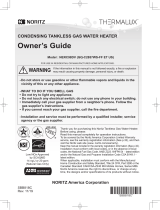
Quick Connect Multi System Installation
• The Quick Connect Multi System allows the installation of two units together utilizing only the Quick
Connect Cord-2.
Typical Plumbing
The Quick Connect Cord-2 is 2m long. Install the units 50 - 457mm apart from each other to
ensure the cord will be able to reach between the units. (See Typical Plumbing diagram).
(If the distance between the two units is too great, not only will the cord not be able to reach,
but the water temperature may also become unstable because of the difference in pipe length
between the two units).
* When connecting 2 devices, use only a
single remote controller.
Note: Connect the remote
controller to only one
of the devices.
System Diagram
• Insulate the hot water piping to prevent heat loss. Insulate and apply heating materials to the
cold water supply piping to prevent heat loss and freezing of pipes when exposed to excessively
cold temperatures.

4
Check the Gas
• Check that the rating plate indicates the correct type of gas.
Check that the gas supply line is sized
for 54.0 kW for this unit.
Check the Power
• The power supply required is 220 - 240V AC, at 50Hz.
Using the incorrect voltage
may result in fi re or electric shock.
Do Not Use Equipment for Purposes Other Than Those Specifi ed
• Do not use for purposes other than increasing the temperature of the water supply, as unexpected
accidents may occur as a result.
Check Water Supply Quality
• If the water supply is hard, acidic or otherwise impure, treat the water with approved methods in
order to ensure full warranty coverage.
Use Extreme Caution if Using With A Solar Pre-Heater
• Using this unit with a solar pre-heater can lead to unpredictable output temperatures and possibly
scalding. If absolutely necessary, use mixing valves to ensure output temperatures do not get to
scalding levels. Do not use a solar pre-heater with the quick-connect multi-system.
Checkup
• Check the fi xing brackets yearly for damage or wear. Replace if necessary.
4.
Before Installation
Caution

5
Caution
• The water heater is designed for external installation only.
Never install it indoors or in a bathroom.
• Consult with the customer concerning the location of installation.
•
Avoid places where fi res are common, such as those where gasoline,
benzene and adhesives are handled, or places in which corrosive
gases (ammonia, chlorine, sulfur, ethylene compounds, acids) are
present.
This may cause incomplete combustion or failures.
• Locate the water heater so that there are no obstacles around the
termination and so that exhaust can't accumulate. Do not enclose the
termination with corrugated metal or other materials.
• Install the water heater in an area that allows for the proper clearances
to combustible and noncombustible construction.
Consult the rating plate on the appliance for proper clearances.
• Do not install the water heater in a place where it may be threatened
by falling objects, such as under shelves.
• Do not install the water heater where the exhaust will blow on outer
walls or material not resistant to heat. Also consider the surrounding
trees and animals.
The heat and moisture from the water heater may cause discoloration
of walls and resinous materials, or corrosion of aluminum materials.
• Avoid installation in places where dust or debris will accumulate.
Dust may block the air-supply opening, causing the performance of
the fan motor to drop and incomplete combustion to occur as a result.
• Install in a location where the exhaust gas fl ow will not be affected by
fans or range hoods.
• Take care that noise and exhaust gas will not affect neighbors.
• Avoid installation in places where special chemical agents
(e.g., hair spray or spray detergent) are used.
Ignition failures and malfunction may occur as a result.
5.
Choosing Installation Site
* Locate the appliance in an area where leakage from the unit or connections will not result in damage
to the area adjacent to the appliance or to the lower fl oors of the structure. When such locations cannot
be avoided, it is recommended that a suitable drain pan, adequately drained, be installed under the
appliance. The pan must not restrict combustion air fl ow.
Internal
installation

6
6.
Installation Clearances
Item
Distance from combustibles
• Maintain the following clearances
from both combustible and
non-combustible materials.
• There must be a clearance of 600mm or
more in front of the exhaust terminal.
• This restriction will not be applied to an
area where an effective shield makes a
clearance of 600mm or more in front of
the exhaust outlet.
Check Illustration
Caution
Clearances to Opening
into Any Building
Combustibles
300 mm or
more
Combustibles
Combustibles
Combustibles
Combustibles
150 mm
or more
150 mm or more
600 mm
or more
10 mm or
more
There must be no
building opening
within this area.
150 mm
or more
150 mm
or more
150 mm
or more
300 mm
or more
Before installing, check for the following:
Install in accordance with relevant building and mechanical codes, as well as any local, state
or national regulations.

7
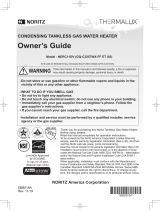
FLUE REQUIREMENTS
Symbol Terminal Position
Dimension
A
Directly below an opening, air brick, opening windows, ect.
300mm
B
Above an opening, air brick, opening window, ect.
300mm
C
Horizontaly to an opening, air brick, opening window, ect.
300mm
D
Below plastic gutters, soil pipes, drain pipes, ect.
75mm
E
Below eaves
200mm
F
Below balconies or car port roof
200mm
G
From vertical drain pipe or soil pipe
150mm
H
From and internal or external corner
300mm
I
Above ground, roof or balcony level
300mm
J
From surface facing the terminal
600mm
K
From terminal facing terminal
1200mm
L
From opening in the car port (eg door, window ect) into the dwelling
1200mm
M
Vertically from terminal on the same wall
1500mm
N
Horizontally from terminal on the same wall
300mm
O
From the wall on which the terminal is mounted
0
P
From a vertical structure on the roof
N/A
Q
Above intersection with the roof
300mm
K
O
O
O
O
M
M
N
N
H
H
C
B
A
G
L
F
I
P
D&E
J

8
Illustration
7.
Installation
Check
4. Drill holes for the remaining four screws.
5. Hang the unit again by the fi rst screw, and then
insert and tighten the remaining four screws.
6. Take waterproofi ng measures so that water does
not enter the building from screws mounting the
device.
• Make sure the unit is installed securely so that it will
not fall or move due to vibrations or earth-quakes.
Securing to the wall
Mounting Bracket
(upper)
Tapping Screw
Location of Screw Hole
1. Drill a single screw hole, making sure to hit a stud.
2. Insert and tighten the screw and hang the unit by
the upper wall mounting bracket.
3. Determine the positions for the remaining four screws
(two for the top bracket and two for the bottom), and
remove the unit.
•
The weight of the device will be applied to the wall. If the strength of the wall is not suffi cient,
reinforcement must be done to prevent the transfer of vibration.
• Do not drop or apply unnecessary force to the device when installing. Internal parts may be
damaged and may become highly dangerous.
• Install the unit on a vertical wall and ensure that it is level.
Locating Screw Holes
Locating Screw Holes
Mounting
Structure
Caution
• When installing with bare hands,
take caution to not infl ict injury.
• Be careful not to hit electrical
wiring, gas, or water piping while
drilling holes.
Item
Installations at Elevations
Above 610m.
• Adjust the dip switches as illustrated in the table to
the right if this water heater is installed at an altitude
of 610m or higher.
• Disconnect power to the water heater before changing
the dip switches. Failure to perform this step will
result in a "73" code displayed on the operation panel
and a cease in operation. If this occurs, disconnect,
then reconnect power to the water heater to reset the
system.
* Do not change any other dipswitches.
* High elevation adjustment.
1
611 - 1,220m
0 - 610m
ON= OFF=

9
Part number:E528, Stainless Mesh Guard
Manufacturer Details: KDS Engineering Limited
Unit 7, Moor Street Industrial Estate
Moor Street
Brierley Hill
West Midlands
England
DY5 3ST
Terminal Guards
A terminal guard is required if persons could come into contact with the terminal or the terminal could
be subject to damage.
If a terminal guard is required, it must be positioned to provide minimum of 50 mm clearance from
any part of the terminal and be central over the terminal.

10
Measuring Gas Pressure
In order to check the gas supply pressure to the unit, a
tap is provided on the gas inlet. Remove the hex head
philips screw from the tap, and connect a manometer
using a silicon tube.
Follow the instructions from the gas supplier.
8.
Gas Piping
The appliance and its individual shutoff valve must be disconnected from the gas supply piping system
during any pressure testing of that system at test pressures in excess of 35 mbar.
The Appliance must be isolated from the gas supply piping system by closing its individual manual shutoff
valve during any pressure testing of the gas supply piping system at test pressures equal to or less than
35 mbar.
The appliance and its gas connections must be leak tested before placing the appliance in operation.
The inlet gas pressure must be within the range specifi ed. This is for the purposes of input adjustment.

11
9.
Water Piping
This appliance is suitable for potable water. Do not use this appliance if any part has been underwater. Immediately
call a qualifi ed service technician to inspect the appliance and replace any part of the control system and gas control
which has been under water.
If the water heater is installed in a closed water supply system, such as one having a backfl ow preventer in the cold
water supply line, means shall be provided to control thermal expansion. Contact ANDREWS WATER HEATERS
TECHNICAL DEPARTMENT FOR ADVICE.
Piping and components connected to the water heater shall be suitable for use with potable water.
Toxic chemicals, such as those used for boiler treatment, shall not be introduced into the potable water.
A water heater used to supply potable water may not be connected to any heating system or components previously
used with a nonpotable water heating appliance.
When water is required in one part of the system at a higher temperature than in the rest of the system, means
such as a mixing valve shall be installed to temper the water to reduce the scalding hazard.
• Flush water through the pipe to clean out metal powder, sand and dirt before connecting it.
• Take appropriate heat insulation measures (e.g., wrapping with heat insulation materials, using electric heaters)
according to the climate of the region to prevent the pipe from freezing.
•
Use a union coupling or fl exible pipe for connecting the pipes to reduce the force applied to the piping.
• Do not use piping with a diameter smaller than the coupling.
• When feed water pressure is too high, insert a depressurizing valve, or take water hammer prevention measures.
• Avoid using joints as much as possible to keep the piping simple.
• Avoid piping in which an air holdup can occur.
• Use approved piping materials.
• If installing the unit on a roof:
If the unit is installed on a roof to supply water to the levels below,
make sure that the water pressure supplied to the unit does not
drop below 2000 mbar. It may be necessary to install a pump system
to ensure that the water pressure is maintained at this level.
Check the pressure before putting the unit into operation.
Failing to supply the proper pressure to the unit may result in
noisy operation, shorter lifetime of the unit, and may cause the
unit to shut down frequently.
Supply water piping
• Do not use PVC piping.
• Mount a check valve and a shut off valve (near
the inlet).
• In order for the client to use the water heater
comfortably, 1000 mbar to 5000 mbar of pressure
is needed from the water supply.
Be sure to check the water pressure. If the
water pressure is low, the water heater cannot
perform to its full capability, and may become a
source of trouble for the client.
Drain piping
• Expansion water may drop from the pressure
prevention device and wet the fl oor. If necessary,
provide drain piping or use a drain hose to
remove the water.
Hot water piping
• Do not use lead or PVC piping.
• The longer the piping, the greater the heat loss.
Try to make the piping as short as possible.
• Use a mixing valve with a low water resistance.
Use shower heads with low pressure loss.
• If necessary, use a pump or other means to
ensure that the supply water pressure to the
inlet of the heater does not fall below
2000
mbar
when the maximum amount of water is
being demanded. Also install a pressure meter
on the inlet. If this is not done, local boiling will
occur inside the water heater causing abnormal
sounds and decreasing the durability of the heat
exchanger.
Ask a qualifi ed plumber to perform the installation
of the plumbing. Observe all applicable codes.
WATER QUARITY
If the heater is in a hard water area a suitable water conditioning device must be installed to prevent the build up of limescale
within the heat exchanger. Heat exchangers damaged by scaling are not covered by the manufacturer’s warranty.
Description pH
Total
Dissolved solids
(TDS)
Total
Hardness
Chlorides Magnesium Calcium Sodium Iron
Maximum
Recommended Levels
6.5 - 9.0
500
mg/liter
150
mg/liter
250
mg/liter
10
mg/liter
20
mg/liter
180
mg/liter
1
mg/liter
Completely insulate
the water inlet and
outlet fittings.
Insulate the water
supply valve completely.
Do not cover the water
drain plug with insulation
so that water in the pipe
can be drained.

12
Do not connect electrical power to the unit until all electrical wiring has been completed.
Consult a qualifi ed electrician
for the electrical work.
10.
Electrical Wiring
Do not turn on the power until the electrical wiring is fi nished.
This may cause electrical shock or damage to the equipment to occur.
Caution
• The electrical supply required by the water
heater is 220 -240V AC at 50 Hz.
The power consumption may be up to 135W.
Use an appropriate circuit.
• Do not disconnect the power supply when not
in use. When the power is off, the freeze pre-
vention in the water heater will not activate,
resulting in possible freezing damage.
•
Do not let the power cord contact the gas piping.
Tie the redundant power cord outside the
water heater. Putting the redundant length
of cord inside the water heater may cause
electrical interference and faulty operation.
Ground
• To prevent an electric shock, always plug pow-
er lead into an earth powerpoint.
i) "A means of disconnection from the supply mains having a contact separation in all poles must be
provided to allow for full disconnection".
ii) Under voltage Cat III conditions should be incorporated in the fi xed wiring in accordance with the wir-
ing regulations.
iii) "If the supply cord is damaged, it must be replaced by the manufacturer or its service agent".
This appliance must be electrically grounded in accordance with Electrical Authority Regulations.
External wiring must be correctly earthed, polarised and in accordance with the relevant standards.
In GB this is BS 6891.
In IE this is the current edition of I.S.813 "Domestic Gas Installations".
The boiler must be connected to a permanent 220 - 240 V ac, 50Hz supply.
Connection of the whole electrical system of the boiler, including any heating controls, to the electrical
supply must be through one common isolator and must be fused 10 Amp maximum.
Isolation should be by a double pole switched fused spur box, with a minimum gap of 3 mm for both
poles. The fused spur box should be readily accessible and preferably adjacent to the appliance. It
should be identifi ed as to its use.
Caution: Label all wires prior to disconnection when servicing controls. Wiring errors can cause improp-
er and dangerous operation.
Verify proper operation after servicing.
Field wiring to be performed at time of appliance installation.
THE APPLIANCE MUST BE EARTHED

13
Remote controller cord
• Use Remote controller cord for any extensions.
• Install according to the National Electrical Code and all applicable local codes.
Connecting Remote Controller Cord to Unit
• Keep the remote controller cord away from the freeze prevention heaters in the unit.
• Tie the redundant cord outside the water heater. Do not put the extra length inside the equipment.
• The remote controller cord can be extended up to 100m with Remote controller cord.
• Use a Y type terminal with a resin sleeve. (Without the sleeve, the copper wire may corrode and
cause problems).
• Be sure to hand tighten when screwing to the terminal block. Power tools may cause damage to
the terminal block.
• Applicable Model
Remote Controller
Remote controller
RC-9018M
WHiX49, LWHiX49, WHiCX56, LWHiCX56
Main
•
The remote controller must be installed in accordance with the installation manual enclosed in the
package.
1. Disconnect electrical power to the water heater.
2. Leave enough slack so that the remote controller cord will not be damaged if the unit is removed
from the wall.
3. Remove the front cover of the heater (4 screws).
4. Pass the remote controller cord through the wiring throughway and into the unit.
5. Connect the Y terminals at the end of the remote controller cord to the terminal block.
6. Secure the remote controller cord with a clamp.
7. Replace the front cover.
WHiCX56 series WHiX49 series
Remote Controller Terminal Remote Controller Terminal
Clamp
Clamp

14
Connecting Quick Connect Cord-2
Connecting the Quick Connect Cord-2 to the two units.
1. Turn off the power.
2. Remove the front cover of the heater (4 screws).
3. Pass the Quick Connect Cord-2 through the wiring
throughway and into the unit.
4. Plug the connector on the Quick Connect Cord-2
to the receptacle inside the unit.
5.
Attach the ground wire of the Quick Connect Cord-2
to the terminal block fi xing plate.
(If the ground wire is not attached, electrical noise
may cause problems).
6. Secure the Quick Connect Cord-2 with a clamp.
7. Replace the front cover.
Wiring Throughway
Coupling Cord
Clamp
Ground wire Connector
(Use one of the vacant holes)
Connector
Caution
For Quick Connect Multi System Installation use part
Quick Connect Cord-2
only. (sold separately).
Quick Connect
Cord-2
"Quick Connect Cord-2" tag
AB
1.Red
2.Black
3.White
4.Green
5.Blue
6.Blue
1.Red
2.Black
3.White
4.Green
5.Blue
6.Blue
1.Red
2.Black
3.White
4.Green
5.Blue
6.Blue
1.White
2.Green
3.Red
4.Black
5.Blue
6.Blue
The wire coloring on the Quick Connect Cord-2 will
not be the same as the wire coloring of the
connection plug inside the unit.
* The remote controller can be connected to
either unit A or B. Do not connect a remote
controller to both units.
* Disconnect the remote controller from either
unit A or B prior to installing the Quick Connect
Cord-2.

15
Note
•
Cutting too large of a hole on the wall may result in failure to properly secure the remote controller.
• Never fasten or loosen unnecessary screws in order to complete the remote controller installation.
• Be sure to check the positions of wall studs or other obstructions when determining the installation
location for the remote controller.
• Secure the remote controller cable with approriate anchors, ties, etc.
• Wire the remote controller cable in an area where it will not be directly affected by heat.
• To embed the remote controller cable in concrete, brick, etc., enclose it in conduit in order to prevent
the remote controller cable from becoming damaged.
• When penetrating a wall containing metal lath, prevent the lath from coming into contact with any
metallic conduit used in order to prevent electrical interference.
• Wiring shall be provided so that the remote controller cable length is 100m or shorter.
• Connect the remote controller cable to the terminal block of the water heater (see Installation
Manual provided with the water heater).
In order to use this product safely, read this installation manual carefully and follow the installation
instructions.
● Potential dangers from accidents during installation and use are described below.
Closely observe these warnings, they are critical to your safety.
CAUTION indicates a potentially hazardous situation which, if not
avoided, may result in minor or moderate injury.
CAUTION
• Do not connect power to the system unit until the remote controller installation is complete.
• Be sure to fasten the mounting screws tightly by hand so that the remote controller will be secure.
* Do not use electric drivers, impact drivers and so forth. Tightening with excessive force may
cause the mounting bracket to be damaged and lead to failures.
• Install the remote controller on an even wall surface.
*
Installing it on an uneven wall surface may cause the bracket to be damaged and lead to failures.
• This remote controller has a built-in speaker which can be damaged by metal shavings resulting
in sound cracking.
Keep the remote controller in a safe location prior to mounting it on the wall to prevent metal
shavings from entering the remote controller.
CAUTION
Requests to Installers
● In order to use the water heater safely, read
this installation guide carefully, and follow the
installation instructions.
● Failures and damage caused by erroneous work
or work not as instructed in this manual are not
covered by the warranty.
● Refer to the Installation Manual provided with
the water heater for complete installation details.
Remote Controller
Installation Guide
The remote controller is not water resistant.
Keep it dry.
CAUTION

16
Post-installation Checks
(1) Check if the remote controller is installed securely.
(2) Verify remote controller operation (see OPERATING
INSTRUCTIONS).
* Press the Power On/Off button approximately 5 seconds
after connecting power to the system.
* Check if the temperature setting on the remote controller
is appropriate.
Explanation to the Customer
Explain the “Important Safety
Information”, “Operation Procedures”
and “Follow-up Service” according
to the Owner's Guide supplied
with the water heater.
Confirmation before the setting
■ Introduction
• Make sure that the power is not turned on (the breaker is “OFF” or the power plug of equipment
is disconnected).
• Check the included parts list.
■ Confirmation before the setting
• Choose a place that is easy to use in consultation with our customers (It is necessary to get the
approval of the visitor).
• Do not be attached to the following place;
1. The place where the temperature becomes higher (near a gas stove)
2. The place where direct rays hit (near a window etc.)
3. The place which requires steam (near a gas stove and a rice cooker etc.)
4. The place which requires a spray (near a hot water tap etc.)
5. The place which requires oil (near a gas stove)
6.The place which uses chemical specialities (Benzine, Oils and fats system detergent etc.)
(1)
(2)
(2)
(2)
(2)
(1)
Included Parts List
(The value in ( ) indicates the quantity.)
Remote Controller
Mounting
bracket
Raised countersunk
head wood screw
Wall anchor
Raised countersunk
head screw
(For junction box
installation)
Machine
screw
■ Confirmation of the remote-control cord
The remote controller cord can be extened up to 100m.Please use the thing of required length
according to the conditions of the spot.
By splicing the cord and using 18 gauge wire to extend the cord to
the appropriate length.For using it, please be sure to attach Y-shaped
terminal with a resin sleeve.
Be careful for a mustache not to come out.
When a mustache comes out, please be sure to reattach Y-shaped terminal.
A mustache contacts other parts and causes failure of apparatus.
Y-shaped terminal
with a resin sleeve
mustache

17
Installation
1. Attach the mounting bracket to the wall.
The parts to be used vary depending on
the attachment method.
*
Never use electric drivers, impact drivers and so forth.
Tightening with excessive force may result in
deformation of the mounting bracket and/or failures.
<When attaching to a junction box>
•
Use the raised countersunk head screws to
attach the mounting bracket to the junction box.
(In this case, the wall anchor and round
countersunk head wood screws are not used.)
<When attaching to a wood surface>
•
Use the raised countersunk head wood screws
to attach the mounting bracket.
(In this case, the wall anchor and raised
countersunk head screws are not used.)
<When attaching to a concrete wall surface>
•
Drill a φ6mm hole, approx. 25mm~30mm
in depth, and hammer in the wall anchor.
Attach the mounting bracket using the raised
countersunk head wood screws.
(In this case, raised countersunk head screws
are not used.)
2. Remove the decorative frame from
the remote controller.
(The remote controller is inserted in
the decorative frame.)
Remove the remote
controller while pulling
the decorative frame
forward.
Decorative frame
Main remote
controller body
3. Connect a Y-shaped terminal of the remote
control cord to a terminal stand of the
remote control in back side.
Push down only section A (
) of an
attach Y-shaped terminal from an insulated
cover (clear) top side.
* Do not remove the insulating cover (clear).
* Be careful about the installation direction
of the Y-shaped terminal.
* Do use an electric driver, the impact
screwdriver absolutely.
*
The position of a terminal stand changes with
kinds of remote control.
Remote controller cords
(Be careful about the
installation direction of
the Y-shaped terminal.)
* Check the terminal is
covered with Section A
( )
of the insulating
cover
(clear, see Fig. 1).
* If the Y-shaped terminal is not covered, the
exposed section may come into contact with the
mounting bracket resulting in improper operation
or failure.
THIS SIDE UP
For exposed wiring, use
scissors or shears to
carefully cut “the wires inlet tab”
of the decorative frame to create
slot for wires before attaching to
wall mount.
Wires inlet tab
Decorative frame
Top
Bottom
Mounting bracket
(accessory part)
Confirm the
orientation of the
mounting bracket.
Raised countersunk
head wood screw
(accessory part)
Top
Bottom
Junction box
Mounting bracket
(accessory part)
Confirm the orientation of the
mounting bracket is correct.
Raised countersunk
head screw
(accessory part)
Top
Bottom
Mounting bracket
(accessory part)
Wall anchor
(accessory part)
Raised countersunk
head wood screw
(accessory part)
Confirm the orientation
of the mounting bracket.
insulated cover (clear) to the front, and

18
Rear side of the remote controller
Fig. 1
Winding around the notches
Pass the remote
controller cords
through the notch.
Section A
Insulating cover
(Do not remove
the cover.)
Mounting bracket
Remote controller cords
4. Secure the remote controller cords by winding
them around the notches as shown in Fig. 1.
For wiring inside the wall
For exposed wiring
5.
Attach the remote controller to the mounting bracket.
Insert the bottom of the remote contoller into
the groove at the bottom of the bracket and
push in the 2 hooks on top of the remote
controller completely.
* If it is dificult to attach, do not try to force it as it
may result in broken hooks. Check for proper
alignment in the groove or for loose wires obstructing
the remote controller.
* Do not install on the
bracket by force, the
hooks may break.
Hooks
Groove
Mounting
bracket
Main remote
controller body
6. Secure the remote using the machine screws.
7. Attach the decorative frame which was removed
in the second step.
Push the 4 corners of the decorative frame until
there is a click.
* Incomplete installation may result in failures
such as switch operation failure.
Note: To remove the decorative frame after
installation of the remote controller and
the frame, pull the entire decorative frame
forward while pressing the sections
indicated (where the ngers are) in the
gure below.
* If it does not come off, insert a flat head
driver into the notch at the bottom of the
decorative frame and slightly twist it to
remove (due caution is required not to
scratch the remote controller, decorative
frame or the wall in doing so).
Click
ClickClick
Put fingers into this gap.
Main remote
controller body
Machine screw
(accessory part)
Click
/