Page is loading ...

www.3Com.com
User Guide
3Com Outdoor 11a Building to Building Bridge and
11bg Access Point
3CRWEASYA73 / WL-575
Part Number 10015232 Rev. AA
Published August, 2006

3Com Corporation
350 Campus Drive
Marlborough, MA
01752-3064
Copyright © 2006 3Com Corporation. All rights reserved. No part of this documentation may be reproduced in any form or by any
means or used to make any derivative work (such as translation, transformation, or adaptation) without written permission from
3Com Corporation.
3Com Corporation reserves the right to revise this documentation and to make changes in content from time to time without
obligation on the part of 3Com Corporation to provide notification of such revision or change.
3Com Corporation provides this documentation without warranty, term, or condition of any kind, either implied or expressed,
including, but not limited to, the implied warranties, terms or conditions of merchantability, satisfactory quality, and fitness for a
particular purpose. 3Com may make improvements or changes in the product(s) and/or the program(s) described in this
documentation at any time.
If there is any software on removable media described in this documentation, it is furnished under a license agreement included with
the product as a separate document, in the hard copy documentation, or on the removable media in a directory file named
LICENSE.TXT or !LICENSE.TXT. If you are unable to locate a copy, please contact 3Com and a copy will be provided to you.
UNITED STATES GOVERNMENT LEGEND
If you are a United States government agency, then this documentation and the software described herein are provided to you
subject to the following:
All technical data and computer software are commercial in nature and developed solely at private expense. Software is delivered as
“Commercial Computer Software” as defined in DFARS 252.227-7014 (June 1995) or as a “commercial item” as defined in
FAR
2.101(a) and as such is provided with only such rights as are provided in 3Com’s standard commercial license for the Software.
Technical data is provided with limited rights only as provided in DFAR 252.227-7015 (November
1995) or FAR 52.227-14 (June
1987), whichever is applicable. You agree not to remove or deface any portion of any legend provided on any licensed program or
documentation contained in, or delivered to you in conjunction with, this User Guide.
Unless otherwise indicated, 3Com registered trademarks are registered in the United States and may or may not be registered in
other countries.
3Com, the 3Com logo, and SuperStack are registered trademarks of 3Com Corporation.
Wi-Fi is a trademark of the Wireless Ethernet Compatibility Alliance.
All other company and product names may be trademarks of the respective companies with which they are associated.
EXPORT RESTRICTIONS: This product contains Encryption and may require US and/or Local Government authorization prior to
export or import to another country.

iii
Contents
1 Introduction
Product Features 1-1
Radio Characteristics 1-2
APPROVED CHANNELS 1-2
Package Checklist 1-3
Hardware Description 1-4
Integrated High-Gain Antenna 1-4
External Antenna Options 1-4
Ethernet Port 1-5
Power Injector Module 1-5
Grounding Point 1-6
Water Tight Test Point 1-6
Wall- and Pole-Mounting Bracket Kit 1-7
System Configuration 1-7
Operating Modes 1-7
Point-to-Point Configuration 1-8
Point-to-Multipoint Configuration 1-8
2 Bridge Link Planning
Data Rates 2-2
Radio Path Planning 2-3
Antenna Height 2-4
Antenna Position and Orientation 2-6
Radio Interference 2-7
Weather Conditions 2-7
Ethernet Cabling 2-8
Grounding 2-8
3 Hardware Installation
Testing Basic Link Operation 3-2
Mount the Unit 3-2

iv
Using the Pole-Mounting Bracket 3-2
Using the Wall-Mounting Bracket 3-4
Connect External Antennas 3-6
Connect Cables to the Unit 3-7
Connect the Power Injector 3-7
Check the LED Indicators 3-9
Align Antennas 3-10
4 Initial Configuration
Networks with a DHCP Server 4-1
Networks without a DHCP Server 4-1
Using the 3Com Installation CD 4-2
Launch the 3COM Wireless Infrastructure Device Manager (Widman)
utility 4-2
Launching the 3com Wireless Interface Device Manager 4-2
First Time Only 4-4
Using the Setup Wizard 4-4
5 System Configuration
Advanced Setup 5-2
System Identification 5-4
TCP / IP Settings 5-5
RADIUS 5-8
Authentication 5-10
Filter Control 5-15
VLAN 5-17
SNMP 5-19
Configuring SNMP and Trap Message Parameters 5-19
Configuring SNMPv3 Users 5-22
Administration 5-23
Changing the Password 5-23
Telnet and SSH Settings 5-24
Upgrading Firmware 5-25
WDS and Spanning Tree Settings 5-28
System Log 5-33
Enabling System Logging 5-33
Configuring SNTP 5-34

v
RSSI 5-35
Radio Interface 5-37
802.11a Interface 5-38
Configuring Radio Settings 5-38
Configuring Common Radio Settings 5-39
802.11b/g Interface 5-43
Configuring Wi-Fi Multimedia 5-45
Security 5-50
Wired Equivalent Privacy (WEP) 5-53
Wi-Fi Protected Access (WPA) 5-57
6 Command Line Interface
Using the Command Line Interface 6-1
Accessing the CLI 6-1
Console Connection 6-1
Telnet Connection 6-2
Entering Commands 6-3
Keywords and Arguments 6-3
Minimum Abbreviation 6-3
Command Completion 6-3
Getting Help on Commands 6-3
Showing Commands 6-4
Partial Keyword Lookup 6-4
Negating the Effect of Commands 6-5
Using Command History 6-5
Understanding Command Modes 6-5
Exec Commands 6-5
Configuration Commands 6-6
Command Line Processing 6-6
Command Groups 6-7
A Troubleshooting
B Cables and Pinouts
Twisted-Pair Cable Assignments B-1
10/100BASE-TX Pin Assignments B-2


vii
TERMINOLOGY
Access Point—An internet working device that seamlessly connects
wired and wireless networks.
Ad Hoc—An ad hoc wireless LAN is a group of computers, each with
wireless adapters, connected as an independent wireless LAN.
Backbone—The core infrastructure of a network. The portion of the
network that transports information from one central location to another
central location where it is unloaded onto a local system.
Base Station—In mobile telecommunications, a base station is the
central radio transmitter/receiver that maintains communications with the
mobile radiotelephone sets within its range. In cellular and personal
communications applications, each cell or micro-cell has its own base
station; each base station in turn is interconnected with other cells’ bases.
BSS—Basic Service Set. It is an access point and all the LAN PCs that are
associated with it.
CSMA/CA—Carrier Sense Multiple Access with Collision Avoidance.
EAP—Extensible Authentication Protocol, which provides a generalized
framework for several different authentication methods.
ESS—Extended Service Set. More than one BSS is configured to become
an ESS. LAN mobile users can roam between different BSSs in an ESS
(ESS-ID, SSID).
Ethernet—A popular local area data communications network, which
accepts transmission from computers and terminals.
Infrastructure—An integrated wireless and wired LAN is called an
infrastructure
configuration.
RADIUS—Remote Access Dial-In User Server is an authentication method
used in conjunction with EAP for 802.1x authentication and session
based keys.
Roaming—A wireless LAN mobile user moves around an ESS and
maintains a continuous connection to the infrastructure network.

viii
RTS Threshold—Transmitters contending for the medium may not be
aware of each other (they are “hidden nodes”). The RTS/CTS mechanism
can solve this problem. If the packet size is smaller than the preset RTS
Threshold size, the RTS/CTS mechanism will not be enabled.
VAP—Virtual Access Point. An access point radio capable of operating as
four separate access points.
VLAN—Virtual Local Area Network. A LAN consisting of groups of hosts
that are on physically different segments but that communicate as
though they were on the same segment.
WEP—Wired Equivalent Privacy is based on the use of security keys and
the popular RC4 encryption algorithm. Wireless devices without a valid
WEP key will be excluded from network traffic.
WDS—Wireless Distribution System.
WPA—Wi-Fi Protected Access.

1-1
1 INTRODUCTION
The 3Com Outdoor 11a Building to Building Bridge and 11bg Access Point system
provides point-to-point or point-to-multipoint bridge links between remote
Ethernet LANs, and wireless access point services for clients in the local LAN area.
It includes an integrated high-gain antenna for the 802.11a radio and can
operate as a “Slave” or “Master” bridge in point-to-multipoint configurations, or
provide a high-speed point-to-point wireless link between two sites that can be
up to 15.4 km (9.6 miles) apart. As a “Master” bridge in point-to-multipoint
configurations it can support connections to as many as six “Slave” units. The
802.11b/g radio requires an external antenna option.
The unit is housed in a weatherproof enclosure for mounting outdoors and
includes its own bracket for attaching to a wall, pole, radio mast, or tower
structure. The unit is powered through its Ethernet cable connection from a
power injector module that is installed indoors.
The wireless bridge system offers a fast, reliable, and cost-effective solution for
connectivity between remote Ethernet wired LANs or to provide Internet access to
an isolated site. The system is also easy to install and operate, ideal for situations
where a wired link may be difficult or expensive to deploy. The wireless bridge
connection provides data rates of up to 108 Mbps.
In addition, both wireless bridge models offer full network management
capabilities through an easy-to-use web interface, a command-line interface, and
support for Simple Network Management Protocol (SNMP) tools.
PRODUCT FEATURES
Supports a 5 GHz point-to-point wireless link up 15.4 km (at 6 Mbps data
rate) using the integrated high-gain 17 dBi antenna
Supports 2.4 GHz or 5 GHz point-to-multipoint links using various external
antenna options

1-2
Provides access point services for the 5 GHz and 2.4 GHz radios using various
external antenna options
Maximum data rate up to 108 Mbps on the 802.11a (5 GHz) radio
Outdoor weatherproof design
IEEE 802.11a and 802.11b/g compliant
Local network connection via 10/100 Mbps Ethernet port
Powered through its Ethernet cable connection to the power injector module
Brackets for wall- or pole-mount options
Security through 64/128/152-bit Wired Equivalent Protection (WEP) or 128-bit
Advanced Encryption Standard (AES) encryption
Scans all available channels and selects the best channel and data rate based
on the signal-to-noise ratio
Manageable through an easy-to-use web-browser interface, command line, or
SNMP network management tools
RADIO CHARACTERISTICS
The IEEE 802.11a and 802.11g standards use a radio modulation technique
known as Orthogonal Frequency Division Multiplexing (OFDM), and a shared
collision domain (CSMA/CA). The 802.11a standard operates in the 5 GHz
Unlicensed National Information Infrastructure (UNII) band, and the 802.11g
standard in the 2.4 GHz band.
IEEE 802.11g includes backward compatibility with the IEEE 802.11b standard.
IEEE 802.11b also operates at 2.4 GHz, but uses Direct Sequence Spread
Spectrum (DSSS) and Complementary Code Keying (CCK) modulation technology
to achieve a communication rate of up to 11 Mbps.
The wireless bridge provides a 54 Mbps half-duplex connection for each active
channel (up to 108 Mbps in turbo mode on the 802.11a interface).
APPROVED CHANNELS
Use of this product is only authorized for the channels approved by each country.
For proper installation, select your country from the country selection list.
To conform to FCC and other country restrictions your product may be limited in
the channels that are available. If other channels are permitted in your country
please visit the 3Com website for the latest software version.

1-3
PACKAGE CHECKLIST
The 3Com Outdoor 11a Building to Building Bridge and 11bg Access Point
package includes:
One 3Com Outdoor 11a Building to Building Bridge and 11bg Access Point
Mounting bracket and hardware
One Weatherproof Category 5 network cable
One Weatherproof Console to RS232 cable
PoE power injector/ Ethernet connector and AC power cord
One grounding screw, not attached
One Quick Start Guide
One CD-ROM containing the Setup Wizard software and User’s Manual
One Warranty Flyer
Optional: One N-type RF coaxial cable
Inform your dealer if there are any incorrect, missing or damaged parts. If
possible, retain the carton, including the original packing materials. Use them
again to repack the product in case there is a need to return it.

1-4
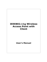
HARDWARE DESCRIPTION
INTEGRATED HIGH-GAIN ANTENNA
The WL-575 bridge includes an integrated high-gain (17 dBi) flat-panel antenna
for 5 GHz operation. With this antenna, in a direct line-of-sight link using a
point-to-point deployment, the range can be as long as 15 km (9.3 miles), with a
6 Mbps data rate.
EXTERNAL ANTENNA OPTIONS
The WL-575 bridge also provides various external antenna options for both 5 GHz
and 2.4 GHz operation. In a point-to-multipoint configuration, an external
high-gain omnidirectional, sector, or high-gain panel antenna can be attached to
communicate with bridges spread over a wide area. The bridge requires a
2.4
GHz external antenna for 802.11b/g operation. The following table
summarizes the external antenna options:
Console Port with
Protective Cap
Ethernet/PoE
Connector
Grounding
Point
Integrated Antenna
Bottom
Top View
N-Type External Antenna
Connector (2.4 GHz)
N-Type External Antenna
Connector (5 GHz)
Console Port
Cap Attachment
Water Tight Test Point
(DO NOT REMOVE)

1-5
External antennas connect to the N-type RF connectors on the wireless bridge
using the optional RF coaxial cables.
Using the external antennas in a point-to-multipoint deployment, the maximum
range for bridge links are:
802.11b,g: 2.2 km
802.11a: 3 km
ETHERNET PORT
The wireless bridge has one 10BASE-T/100BASE-TX 8-pin DIN port that connects
to the power injector module using the included Ethernet cable. The Ethernet
port connection provides power to the wireless bridge as well as a data link to the
local network.
The wireless bridge appears as an Ethernet node and performs a bridging
function by moving packets from the wired LAN to the remote end of the wireless
bridge link.
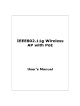
POWER INJECTOR MODULE
The wireless bridge receives power through its network cable connection using
power-over-Ethernet technology. A power injector module is included in the
wireless bridge package and provides two RJ-45 Ethernet ports, one for
connecting to the wireless bridge (Output), and the other for connecting to a
local LAN switch (Input).
The Input port uses an MDI (i.e., internal straight-through) pin configuration. You
can therefore use straight-through twisted-pair cable to connect this port to most
Item Antenna Type Gain (dBi) Horizontal
HPBW*
(Degrees)
Vertical
HPBW*
(Degrees)
2.4 GHz 5.0 GHz
3CWE591 3Com 6/8 dBi Dual-Band Omni 6 8 360 5GHz: 20
2.4GHz: 30
3CWE596
3Com 18/20 dBi Dual-Band Panel
18 20 18 19
3CWE598
3Com 8/10 dBi Dual-Band Panel
8 10 60 60
* Half-power beam width
NOTE: The power injector module does not support Power over Ethernet (PoE)
based on the IEEE 802.3af standard. The wireless bridge unit must always be
powered on by being connected to the power injector module.

1-6
network interconnection devices such as a switch or router that provide MDI-X
ports. However, when connecting the access point to a workstation or other
device that does not have MDI-X ports, you must use crossover twisted-pair cable.
The wireless bridge does not have a power switch. It is powered on when its
Ethernet port is connected to the power injector module, and the power injector
module is connected to an AC power source. The power injector includes one
LED indicator that turns on when AC power is applied.
The power injector module automatically adjusts to any AC voltage between
100-240 volts at 50 or 60 Hz. No voltage range settings are required.
GROUNDING POINT
Even though the wireless bridge includes its own built-in lightning protection, it is
important that the unit is properly connected to ground. A grounding screw is
provided for attaching a ground wire to the unit.
WATER TIGHT TEST POINT
Input Output
Ethernet and Power
to Wireless Bridge
LED Indicator
AC Power Socket
(Hidden)
Ethernet from Local
Network
WARNING: The power injector module is designed for indoor use only. Never mount
the power injector outside with the wireless bridge unit.
!
CAUTION: Do not remove or loosen this screw. Doing so could lead to damage
of the unit.

1-7
WALL- AND POLE-MOUNTING BRACKET KIT
The wireless bridge includes a bracket kit that can be used to mount the bridge to
a wall, pole, radio mast, or part of a tower structure.
SYSTEM CONFIGURATION
At each location where a unit is installed, it must be connected to the local
network using the power injector module. The following figure illustrates the
system component connections.
OPERATING MODES
The 3Com Outdoor 11a Building to Building Bridge and 11bg Access Point system
provides access point or bridging services through either the 5 GHz or 2.4 GHz
radio interfaces.
The unit supports both point-to-point and point-to-multipoint bridge modes.
Wireless bridge units can be used as regular 802.11a/b/g access points connected
to a local wired LAN, providing connectivity and roaming services for wireless
clients in an outdoor area. Units can also be used purely as bridges connecting
remote LANs. Alternatively, you can employ both access point and bridging
functions together, offering a flexible and convenient wireless solution for many
applications.
Indoor Outdoor
LAN Switch
AC Power
Power
Injector
Wireless Bridge Unit
Ground Wire
Ethernet Cable
Ethernet
Cable
External Antenna
RF Coaxial Cable
Lightning
Arrestor

1-8
The wireless bridge modes connect two or more wired networks, for example
networks in different buildings with no wired connections. You will need a 3Com
Outdoor 11a Building to Building Bridge and 11bg Access Point unit on both
sides of the connection. The wireless bridge can connect up to six remote
networks.
When using bridge mode on a radio band, only wireless bridge units can
associate to each other. Wireless clients can only associate with the unit using a
radio band set to access point mode.
POINT-TO-POINT CONFIGURATION
Two bridges can form a wireless point-to-point link using their 5 GHz (802.11a)
integrated antennas. A point-to-point configuration can provide a limited data
rate (6 Mbps) link over a long range (up to 15.4 km), or a high data rate (108
Mbps) over a short range (1.3 km).
POINT-TO-MULTIPOINT CONFIGURATION
A wireless bridge set to “Master” mode can use an omnidirectional antenna to
connect to as many as six bridges in a point-to-multipoint configuration. There
can only be one “Master” unit in the wireless bridge network, all other bridges
must be set as “Slave” units.
The following figure shows a point-to-multipoint “star” configuration with one
bridge set to “Master” and using an omnidirectional antenna.

1-9
The following figure shows a point-to-multipoint “in-line” configuration with one
bridge set to “Master” and using a directional panel antenna.
19° Beam
Angle

1-10

2-1
2 BRIDGE LINK PLANNING
The 3Com Outdoor 11a Building to Building Bridge and 11bg Access Point
supports fixed point-to-point or point-to-multipoint wireless links. A single link
between two points can be used to connect a remote site to larger core network.
Multiple bridge links can provide a way to connect widespread Ethernet LANs.
For each link in a wireless bridge network to be reliable and provide optimum
performance, some careful site planning is required. This chapter provides
guidance and information for planning your wireless bridge links.
NOTE: The planning and installation of the wireless bridge requires professional
personnel that are trained in the installation of radio transmitting equipment.
The user is responsible for compliance with local regulations concerning items
such as antenna power, use of lightning arrestors, grounding, and radio mast or
tower construction. Therefore, it is recommended to consult a professional
contractor knowledgeable in local radio regulations prior to equipment
installation.

2-2
DATA RATES
Using the 5.0 GHz integrated antenna, two WL-575 bridges can operate over a
range of up to 15.4 km (9.6 miles) or provide a high-speed connection of
54
Mbps (108 Mbps in turbo mode). However, the maximum data rate for a link
decreases as the operating range increases. A 15.4 km link can only operate up to
6 Mbps, whereas a 108 Mbps connection is limited to a range of 1.3 km.
When you are planning each wireless bridge link, take into account the maximum
distance and data rates for the various antenna options. A summary for 5.0 GHz
(802.11a) antennas is provided in the following table.
.
Distances Achieved Using 17 dBi Integrated Antennas
Data Rate Distance
6 Mbps 15.4 km
9 Mbps 14.7 km
12 Mbps 14 km
18 Mbps 12.8 km
24 Mbps 11.1 km
36 Mbps 6.5 km
48 Mbps 2.9 km
54 Mbps 1.8 km
12 Mbps Turbo 13.4 km
18 Mbps Turbo 12.8 km
24 Mbps Turbo 12.2 km
36 Mbps Turbo 11.1 km
48 Mbps Turbo 8.2 km
72 Mbps Turbo 4.6 km
96 Mbps Turbo 2.1 km
108 Mbps Turbo 1.3 km
Distances provided in this table are an estimate for a typical
deployment and may be reduced by local regulatory limits.
For accurate distances, you need to calculate the power link
budget for your specific environment.
/