01
Déballage du réfrigérateur
Uʪϑϑʪθθʪі̷ʪϑ
ɵͱЇ̷ͱ͝ϑ
đՑуՌՋՌՋΧ̈ʽʀʪϑ
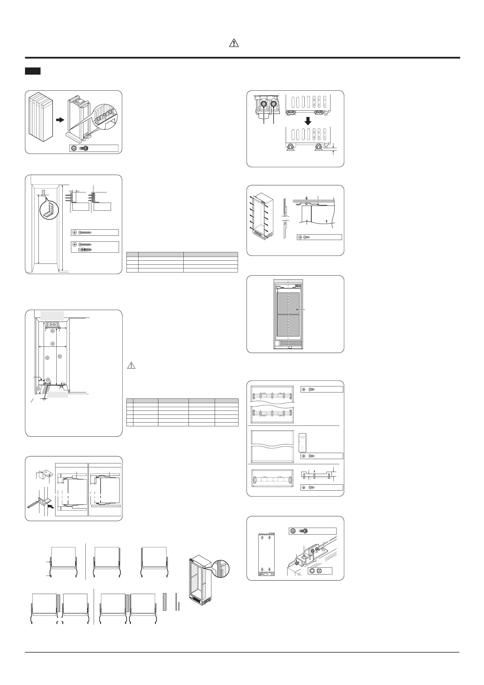
• Retirez les deux xations de la palette en
dévissant les boulons (six par attache).
02
Fixation du support antibasculement
Hauteur de
l'armoire
- Pour les modèles de 18", 24" et 30" :
3 pièces
- Pour les modèles de 36" : 6 pièces
- 3 vis/verrous de soutien par support
đՏуՎՐՎΧ̈ʽʀʪϑ
Mur en bois
Mur en béton
đՏуՎՐՎΧ̈ʽʀʪϑ
ՑуՎՋ ՎΧ̈ʽʀʪϑ
ՍٓطՐՋظ
Aɇ̷ʪʒʪϑΧɇʀʪ͔ʪ͝ϩطɵͱ̈ϑظ
ΧΧɇθʪ̷̈ ΧΧɇθʪ̷̈
• La hauteur du support est mesurée à partir
du sol et dépend de la hauteur de l’armoire.
• Fixez les supports antibasculement. Assurez-
vous que les vis serrent fermement le
support.
• Les supports antibasculement doivent
s’allonger au moins de 2” (50 mm) sur
l’appareil pour le sécuriser. Si cette longueur
minimale ne peut pas être respectée pour
des raisons liées à la structure, l’alternative
consiste à xer une cale d’espacement (en
bois) derrière l’angle antibasculement.
Hauteur de l’armoire A
1 83 1/2”(2121 mm) 79 1/2”(2019 mm)
2 83 3/4”(2127 mm) 79 5/8”(2023 mm)
3 84”(2134 mm) 79 7/8”(2030 mm)
4 84 1/4”(2140 mm) 80 1/8”(2036 mm)
Pour les modèles de 36”, placez 2 supports antibasculement à intervalles
réguliers. Pour les autres modèles, utilisez un seul support antibasculement.
03
Conditions spéciques à l’armoire
5”
(127)
D
A
C
E
F
B
Emplacement de
l'alimentation
électrique
6”
(154)
ø1/4”(6.5)
1”
(25.4)
Emplacement
de l'arrivée d'eau
A : Largeur de l’armoire
B : Profondeur de l’armoire
C : Hauteur de l’armoire
D : Emplacement de la
largeur de l’alimentation
électrique
E : Emplacement
de la hauteur de
l’alimentation électrique
F : Emplacement de la prise
d’alimentation en eau
*B : inclut une épaisseur de panneau de porte
standard avec 3/4”.
*Une installation à l’intérieur d’une armoire
de cette largeur permet à l’habillage du
réfrigérateur d’être directement xé aux
armoires autour du produit.
• Branchez le cordon d’alimentation du
réfrigérateur à une prise correctement
mise à la terre. Réglez le Commutateur
d’alimentation principal sur la position «I»
(ACTIVATION).
• Vériez que le réfrigérateur est alimenté
en ouvrant la porte an de vérier que les
lumières intérieures sont allumées.
ATTENTION
Une fois le branchement d’alimentation
effectué, tournez le Commutateur
d’alimentation principal sur la position «O»
(DÉSACTIVATION).
18” 24” 30” 36”
A
18’(457 mm) 24”(610 mm) 30”(762 mm) 36”(915 mm)
B
25”(635 mm) 25”(635 mm) 25”(635 mm) 25”(635 mm)
C
84”(2,134 mm) 84”(2,134 mm) 84”(2,134 mm) 84”(2,134 mm)
D
8”(203 mm) 14”(356 mm) 20”(508 mm) 26”(660 mm)
E
80”(2032 mm) 80”(2032 mm) 80”(2032 mm) 80”(2032 mm)
F
3”(76 mm) 5 1/2”(140 mm) 6”(152 mm) 9”(228 mm)
04
Placer le réfrigérateur dans son caisson
ƟцΧʪʒʪϑЇΧʪθΧͱϑ̈ϩ̈ͱ͝
ΧΧɇθʪ̷̈ ΧΧɇθʪ̷̈
A˵ɑϑϑ̈ϑ̷ɇϩʭθɇ̷ʒʪ̷ɇθ͔ͱ̈θʪ
ǤЇʪʒЇ˵ɇЇϩ
ǤЇʪʒЇ˵ɇЇϩ
ƟцΧʪϑɇ͝ϑʀɇʒθʪ
A˵ɑϑϑ̈ϑ̷ɇϩʭθɇ̷ʒʪ̷ɇθ͔ͱ̈θʪ
ÜϑΧͱϑ̈ϩ̈˙ʒʪϑʪθθɇ˝ʪ
طɇ̈ʒʪɇЇΧͱϑ̈ϩ̈ͱ͝͝ʪ͔ʪ͝ϩظ
ƊЇΧʪθΧͱϑ̈ϩ̈ͱ͝
AθʪЇу
Aͱ͔Χɇϩ̈ɵ̷̈̈ϩʭ
Χɇ͝͝ʪɇЇ
Aͱ͔Χɇϩ̈ɵ̷̈̈ϩʭ
Χɇ͝͝ʪɇЇ
Aͱ͔Χɇϩ̈ɵ̷̈̈ϩʭ
Χɇ͝͝ʪɇЇ
Aͱ͔Χɇϩ̈ɵ̷̈̈ϩʭ
Χɇ͝͝ʪɇЇ
Ռժٗٗ
طՏՋ͔͔ظ
Ռժٗٗ
طՏՋ͔͔ظ
• Avant de déplacer le réfrigérateur dans son
caisson, xez les isolants latéraux du meuble
sur les deuxcôtés du réfrigérateur, de façon
appropriée. Reportez-vous aux illustrations
ci-dessous.
• Selon le type d’armoire, un dispositif de
serrage (aide au positionnement) peut être
utilisé pour aligner le panneau personnalisé
de la porte du réfrigérateur avec l’armoire en
traçant une ligne verticale sur l’armoire.
• Positionnez l’armoire côté châssis pour
l’aligner avec la ligne verticale.
Эɇ͝ϩ
θθ̈ʽθʪՌՓٓ؏ՍՏٓ؏ՎՋٓ؏ՎՑٓ ՍՏٓ؏ՎՋٓ
Aͱ͝˝ʭ̷ɇϩʪЇθŵʭ˙θ̈˝ʭθɇϩʪЇθ Aͱ͝˝ʭ̷ɇϩʪЇθ ŵʭ˙θ̈˝ʭθɇϩʪЇθ
ՌՓٓ؏ՍՏٓ؏ՎՋٓ؏ՎՑٓ ՎՑٓ
Ռ؏Տٓ
طՑ͔͔ظ
Ռ؏Փٓ
طՎ͔͔ظ
̈ϑͱ̷ɇ͝ϩ
ʀ˵ɑϑϑ̈ϑ
ĮƸ
ǤЇʪʒʪʒʪϑϑЇϑ
Эɇ͝ϩ
θθ̈ʽθʪՌՓٓ؏ՍՏٓ؏ՎՋٓ ՎՑٓՎՑٓ
ǤЇʪ̷ɇϩʭθɇ̷ʪ
Fixation des isolants: Pour plus d’informations, reportez-vous au manuel d'installation.
• Installation d'un seul appareil
Exemple d'installation
d'un appareil de 36"
• Installation d'un duo d'appareils
Guide d’installation
05
Mise à niveau du réfrigérateur
Эɇ͝ϩ
θɵθʪɇ̟Їϑϩɇɵ̷ʪ
طՎ؏ՓٓՌՋ͔͔ظ
ՍՋ͔͔͔ɇӱ
ƟцΧʪʒʪЭʭθ̈͝طɇ̟Їϑϩʪ͔ʪ͝ϩʒʪ̷ɇ˵ɇЇϩʪЇθظ
θθ̈ʽθʪ
• Fixez le cache supérieur du réfrigérateur sur
le crochet de la partie supérieure avant du
châssis.
• En utilisant votre perceuse et le foret indiqué
ci-dessous, engagez chacun des arbres
d’ajustement du réfrigérateur en rotation et
mettez à niveau le réfrigérateur. (SH ↑, SAH
↓) Ajustez l’écart entre le meuble et le cache
du châssis supérieur à 1/8 pouce (3 mm).
• Les pieds de mise à niveau avant et arrière
ont un ajustement de hauteur maximale de
3/4 pouces (20 mm).
06
Fixation du réfrigérateur
ǤЇʪʒЇ˵ɇЇϩ
طƟ²ظđՏуՌՑՌՍΧ̈ʽʀʪϑ
Aͱ͔Χɇϩ̈ɵ̷̈̈ϩʭ
Χɇ͝͝ʪɇЇ
θ͔ͱ̈θʪ
A˵ɑϑϑ̈ϑ̷ɇϩʭθɇ̷ʒʪ̷ɇθ͔ͱ̈θʪ
A˵ɑϑϑ̈ϑ̷ɇϩʭθɇ̷
ʒʪ̷ɇθ͔ͱ̈θʪ
k͔Χ̷ɇʀʪ͔ʪ͝ϩѣуʪ
• Fixez le réfrigérateur dans son caisson avec
des vis (TH) M4 x 16 (6 vis par côté, comme
indiqué sur le schéma).
07
Fixation de l’isolation du panneau avant
• Fixez l’isolation sur la partie avant de la
porte du réfrigérateur. (Assurez-vous que la
position de montage est correcte).
08
Fixation des supports du panneau personnalisé de
la porte
²ƸƟ Panneau
ط²ظđՏуՌՏՍՋΧ̈ʽʀʪϑ
ƊƸťՌՋΧ̈ʽʀʪϑ؏ÃĘ ՌՋΧ̈ʽʀʪϑ
²ƸƟ
9Ɗ
Panneau
Panneau
Modèle
For Lower
(Align the bottom of the panel)
For Upper
(Align the top of the panel)
BRACKET TEMPLATE
COLUMN
Align the side of the panel
Align the side of the panel
ط²ظđՏуՌՏՍՋΧ̈ʽʀʪϑ
ƊƸťՌՋΧ̈ʽʀʪϑ؏ÃĘ ՌՋΧ̈ʽʀʪϑ
ƟθͱЇʒʪӬϑ
Avant
ծٓ
կٓ
Arrière
ط²ظđՏуՌՏՍՋΧ̈ʽʀʪϑ
ƊƸťՌՋΧ̈ʽʀʪϑ؏ÃĘ ՌՋΧ̈ʽʀʪϑ
Type de STS
9Ɗ
Type de bois
Type de arrière encastré
Ǥ̈ϑ
ƊЇΧΧͱθϩ
Panneau personnalisé: STS
• Enfoncez les 10 vis sur la partie supérieure
et inférieure des supports, comme indiqué
sur le schéma. (Les autres trous de chaque
côté du support ont une autre utilité).
Panneau personnalisé : bois, autre
• Le modèle vous indique la position du
support et des trous.
• Marquez les positions des trous sur le
panneau selon le modèle et insérez les vis
dans les trous.
Panneau personnalisé : arrière encastré, autre
• Si le panneau ne peut pas être xé au centre
du support en raison de sa conception,
utilisez les trous de vis adaptés de chaque
côté du support pour xer le panneau.
09
Alignement du panneau
đʭʀɇ̈͝ϑ͔ʪϑ
ʒɇ̟Їϑϩʪ͔ʪ͝ϩʒЇ
Χɇ͝͝ʪɇЇ
9ͱЇ̷ͱ͝ɞ
ʒͱЇɵ̷ʪΧɇϑ
Ǥ̈ϑ̷ɇϩʭθɇ̷ʪ
Ǥ̈ϑՍ
Ǥ̈ϑՌ
đՑуՌՍՌՍΧ̈ʽʀʪϑ
A˵ɇαЇʪՌՍӬϑΧɇθΧͱθϩʪ
đՓ
• Il y a deux mécanismes d’ajustement de
panneau au-dessus et deux en dessous de la
porte.
• Ajustez le panneau de sorte qu’il soit aligné
avec le meuble autour.
• Une vis latérale pour déplacer le panneau
d’un côté à l’autre ; la vis 1 pour déplacer le
panneau vers l’avant/l’arrière ; la vis 2 pour
xer le panneau en place.
• Pour xer le panneau sur la porte, vissez
les écrous sur les boulons à double pas. (2
écrous par porte)
FR
ATTENTION
Veuillez lire attentivement les instructions d'installation avant d'installer l'appareil.

