Page is loading ...

SY-5EMM
Super 7
TM
Mainboard
************************************************
Pentium
®
Class CPU supported
ETEQ82C663 PCI/AGP Mainboard
Micro-ATX Form Factor
************************************************
User's Guide
&
Technical Reference

SOYO™ SY-5EMM
ii
About This Guide
This User's Guide is for assisting system manufacturers and end users in setting up
and installing the mainboard. Information in this guide has been carefully checked for
reliability; however, no guarantee is given as to the correctness of the contents. The
information in this document is subject to change without notice.
Copyright Notice
Copyright 1998, Soyo Computer Inc. All rights reserved. This manual is copyrighted
by Soyo Computer Inc. You may not reproduce, transmit, transcribe, store in a
retrieval system, or translate into any language, in any form or by any means,
electronic, mechanical, magnetic, optical, chemical, manual or otherwise, any part of
this publication without express written permission of Soyo Computer Inc.
Trademarks
Soyo is a registered trademark of Soyo Computer Inc. All trademarks are the property
of their owners.
Disclaimer
Soyo Computer Inc. makes no representations or warranties regarding the contents
of this manual. We reserve the right to revise the manual or make changes in the
specifications of the product described within it at any time without notice and without
obligation to notify any person of such revision or change. The information contained
in this manual is provided for general use by our customers. Our customers should be
aware that the personal computer field is the subject of many patents. Our customers
should ensure that their use of our products does not infringe upon any patents. It is
the policy of Soyo Computer Inc. to respect the valid patent rights of third parties and
not to infringe upon or assist others to infringe upon such rights.
Restricted Rights Legend
Use, duplication, or disclosure by the Government is subject to restrictions set forth in
subparagraph (c)(1)(ii) of the Rights in Technical Data and Computer Software clause
at 252.277-7013.
Product Rights
Products mentioned in this manual are mentioned for identification purpose only.
Product names appearing in this manual may or may not be registered trademarks or
copyrights of their respective companies.
If you need any further information, please come to our home page on the Internet.
The address is "http://www.soyo.com.tw".
Edition: September 1998
Version 1.0
5EMM SERIAL
FC
C
Tested To Comply
With FCC Standards
FOR HOME OR OFFICE USE
POST CONSUMER
RECYCLED PAPER
100%

Table of Contents SY-5EMM
iii
Table of Contents
SY-5EMM MAINBOARD LAYOUT....................................................... 1
CHAPTER 1 INTRODUCTION........................................................... 2
1-1 KEY FEATURES ............................................................ 2
1-2 HANDLING THE MAINBOARD...................................... 5
1-3 ELECTROSTATIC DISCHARGE PRECAUTIONS......... 5
CHAPTER 2 HARDWARE SETUP.................................................... 6
2-1 PREPARATIONS......................................................6
2-2 UNPACKING THE MAINBOARD...............................7
2-3 INSTALLATION GUIDE.............................................8
CHAPTER 3 BIOS SETUP UTILITY................................................ 36
3-1 STANDARD CMOS SETUP......................................... 38
3-2 BIOS FEATURES SETUP............................................ 41
3-3 CHIPSET FEATURES SETUP..................................... 47
3-4 POWER MANAGEMENT SETUP................................ 51
3-5 PNP/PCI CONFIGURATION SETUP........................... 56
3-6 LOAD SETUP DEFAULTS ........................................... 59
3-7 LOAD BIOS DEFAULTS............................................... 59
3-8 INTEGRATED PERIPHERALS .................................... 60
3-9 SUPERVISOR PASSWORD........................................ 64
3-10 USER PASSWORD...................................................... 65
3-11 IDE HDD AUTO DETECTION...................................... 66
CHAPTER 4 DRIVERS INSTALLATION ......................................... 67
CHAPTER5 ALS120 AUDIO DRIVER INSTALLATION.................. 70
5-1 WINDOWS 3.1............................................................. 71
5-2 DOS UTILITY (DOSINST.EXE).................................... 72
5-3 WINDOWS 95/98......................................................... 73
5-4 WINDOWS NT 3.5/4.0 ................................................. 75
5-5 SETUP UTILITY PROGRAM.....................................75
5-6 TROUBLESHOOTING ................................................. 77

Mainboard Features SY-5EMM
1
SY-5EMM Mainboard Layout
Key Features
Ø Super 7
TM
Platform
Ø 512KByte L2 cache
Ø Supports CPU voltage from
2.0v to 3.5v in 0.1v increments
Ø PC97, ACPI, Ultra DMA/33MHz
Ø Power-on by modem or alarm
Ø Supports Wake On LAN (WOL)
Ø Fan-off in Suspend mode
Ø 5x32-bit bus mastering PCI slots
Ø 2xUSB ports, 1xIrDA port
Ø Supports multiple-boot function
Ø DMI utility
Back Panel
SY-5EMM Platform
JP44
13
AGP Slot
ISA Slot #1
ATX Power
3V
Lithium
Battery
ETEQ
EQ82C6629B
P.B. SRAM
64Kx64
TAG 32Kx8
JP19
JP20
JP5
1
3
IDE 2
1
FDC
1
IDE 1
1
JP10
1
3
JP8
JP9
ETEQ
EQ82C6638
DIMM 2
DIMM 1
SIMM1
SIMM2
SMC
FDC37C669Q
ALS120
*
1
CPUFAN
1
CHAFAN
PCI Slot #2
PCI Slot #3
JP30
JP1JP2
7
5
3
1
2
4
6
8
PCI Slot #1
IR
5
1
SW1
ON
RST
PW2
SPK
Keylock
Power
LED
Turbo
LED
HDD
LED
_ _
+
+
Flash BIOS
Flash BIOS
JP16
JP17
USB
COM1
COM2
PRT
JOYSTICK
LINE-OUT
LINE-IN
MIC JACK
PS/2 KB
Connector
PS/2 Mouse
Connector
1
4
14
1

Introduction SY-5EMM
2
Chapter 1
INTRODUCTION
The SY-5EMM AGP/PCI mainboard is a high-performance Micro-
ATX form-factor system board. SY-5EMM uses the ETEQ82C663
PCI Chipset technology and supports Pentium
®
class processors.
This mainboard is fully compatible with industry standards and adds
many technical enhancements.
1-1 KEY FEATURES
l CPU
Ø Supports Intel Pentium Processor P54C/P55C series
CPUs featuring speeds of 100-233 MHz
Ø Supports Cyrix 6x86/6x86L/6x86MX CPUs with PR150-
PR266 speeds and Cyrix M II-300-350 CPU
Ø Supports AMD K5 CPUs running at PR100-PR166 speeds,
AMD K6 CPUs running at speeds of 166-300 MHz speeds,
and AMD K6-2 266-350 CPU
Ø Features Socket 7 for CPU easy upgrade
Ø Supports P54C/P55C series SIMM Mode and CPU Stop
Clock
l L2 Cache Controller
Ø On-board 512KB Level 2 Pipeline Burst SRAM Cache
l DRAM Controller
Ø Supports 2 strips of 168-pin SDRAM unbeffured DIMM
2 x 168-pin DIMM banks support 8/16/32/64/128/256 MB
unbuffered DIMM modules
Ø Support 2 strips of 72-pin FPM/EDO SIMM 2 x 72-pin
SIMM banks support 8/16/32/64 MB SIMM modules
Ø Memory configuration:
u System memory: 8MB to 640MB with EDO/SDRAM

Introduction SY-5EMM
3
SY-5EMM PLATFORM FEATURES
Board Size 4-layer PCB, 20x24.5cm(7.9” x9.5” ), Micro-ATX Form
Factor
Socket 7 Socket for Pentium
®
class CPUs
with Host Bus frequency of 66/100MH; Supports:
Ø Intel Pentium
®
Processors P54C/P55C (100-233MHz)
Ø Cyrix 6x86™ (PR166+-PR200+),
Cyrix 6x86 MX™ (PR166-PR266) and Cyrix M II™
(300~350)
Ø AMD K5™ (PR100-PR166), and AMD K6™ (166-300)
and AMD K6™-2 (266~350)
Chipset ETEQ82C663 PCI/AGP Bus Chipset
ATX Power 20-pin Male Connector
CPUFAN 3-pin CPU Cooling Fan Connector
CHAFAN 3-pin Chassis Cooling Fan Connector
Memory DIMM Bank (DIMM1 & DIMM2)
Ø 168-pin Unbuffered SDRAM DIMM Module
Ø Supports 8~256MB DIMM in each Bank
Ø Supports ECC configuration
SIMM Bank (SIMM1 &SIMM2)
Ø Supports 8-64MB
Ø 2strips of 72-pin SIMM
BIOS System BIOS built-in, Award BIOS
Ø APM, ACPI and "Plug-and-Play" function
Ø Supports multiple-boot function
Ø DMI utility
PCI Slots 3 x 32-bit Bus Mastering Slots
ISA Slots 2 x 16-bit ISA Slots
IDE1, IDE2 2 x 40-pin Bus Mastering E-IDE/ATAPI Ports
Ø IDE1: Primary IDE Device Connector
Ø IDE2: Secondary IDE Device Connector
Ø Supports Ultra DMA/33
FDC 1 Floppy Disk Drive (FDD) Port
(Supports 1.2MB/1.44MB/2.88MB and LS120/3-mode FDD)
SIR 5-pin Serial Infrared Device Connector
Keylock 5-pin KeyLock Connector
Reset 2-pin Reset Switch Connector
Speaker 4-pin PC Speaker Connector
TB_LED 2-pin Turbo LED Connector

Introduction SY-5EMM
4
HDD_LED 2-pin IDE Device LED Connector
PWRBT ATX Power On/Off Switch 2-pin Connector
JP5 CMOS Clear Jumper
JP8 CPU bus clock frequency Jumper
JP9, JP10 SDRAM frequency Jumpers
JP1, JP2 Single or Dual voltage selection Jumper
JP30 CPU Voltage Selection Jumper
JP16, JP17 2 x CD Line-in 4-pin Connectors
JP19, JP20 Enabled/Disabled Onboard Sound Function Jumpers
JP44 WOL (Wake-On-LAN) 3-pin Connector
SW1 CPU frequency Settings Jumper
BACK-PANEL FEATURES
PRT 1 x Onboard 26-pin Female Parallel Printer Port
COM1, COM2 2 x Onboard RS-232 Serial Port
PS/2 KB 1 x Onboard PS/2 Keyboard Connector
PS/2 Mouse 1 x Onboard PS/2 Mouse Connector
USB1, USB2 2 x Onboard USB
(Universal Serial Bus)
Connectors
JOYSTICK 1 x Onboard 15-pin Joystick Port
LINE-OUT 1 x Onboard Line-out Audio Stereo Jack
LINE-IN 1 x Onboard Line-in Audio Stereo Jack
MIC JACK 1 x Onboard Microphone Stereo Jack

Introduction SY-5EMM
5
1-2 HANDLING THE MAINBOARD
To avoid damage to your mainboard, follow these simple rules while
unpacking:
Ø Before handling the mainboard, ground yourself by grasping an
unpainted portion of the system's metal chassis.
Ø Remove the mainboard from its anti-static packaging. Hold the
mainboard by the edges and avoid touching its components.
Ø Check the mainboard for damage. If any chip appears loose,
press carefully to seat it firmly in its socket.
Warning: Do not apply power if the mainboard appears
damaged. If there is damage to the board, contact your
dealer immediately.
1-3 ELECTROSTATIC DISCHARGE PRECAUTIONS
Make sure to ground yourself before handling the mainboard or
other system components. Electrostatic discharge can easily
damage the components. Note that you must take special
precautions when handling the mainboard in dry or air-conditioned
environment.
To protect your equipment from electrostatic discharge, take the
following precautions:
Ø Do not remove the anti-static packaging until you are ready to
install.
Ø Ground yourself before removing any system component from
its protective anti-static packaging. (To ground yourself, grasp
the expansion slot covers or other unpainted portions of the
computer chassis.)
Ø Frequently ground yourself while working or use a grounding
strap.

Introduction SY-5EMM
6
Chapter 2
HARDWARE SETUP
Congratulations on your purchase of SY-5EMM Super 7
TM
Mainboard. You are about to install and connect your new
mainboard.
Note: Do not unpack the mainboard from its protective
anti-static packaging until you have made the following
preparations.
2-1 Preparations
Gather and prepare all the following hardware equipment to
complete the installation successfully:
1. Pentium processor with CPU cooling fan.
2. DIMM memory module
3. Computer case and chassis with adequate power supply unit
4. Monitor
5. Keyboard
6. Pointing Device (PS/2 mouse)
7. Speaker(s) (optional)
8. Disk Drives: HDD, CD-ROM, Floppy drive…
9. External Peripherals: Printer, Plotter, and Modem (optional)
10. Internal Peripherals: Modem and LAN cards (optional)
Frequently Asked Questions:
l Do I need to install a sound card?
The answer is NO since, for your convenience, the SY-5EMM
mainboard already features built-in audio-stereo ports (Line-in,
Line-out, and Microphone).
l What kind of speaker can connect to "Line-out" port?
This motherboard requires a speaker with built-in amplifier to
generate proper output sound volume.

Introduction SY-5EMM
7
2-2 Unpacking the Mainboard
When unpacking the mainboard, check for the following items:
Ø The SY-5EMM ETEQ82C663 PCI/AGP Mainboard
Ø This Quick Start Guide *
Ø The Installation CD-ROM *
Ø One IDE Device Flat Cable
Ø One Floppy Disk Drive Flat Cable
* If your board comes with a driver disc and a paper manual, the Quick Start Guide
and the CD-ROM are not included in the package.
Warning: Do not unpack the mainboard from its anti-static
packaging until you are ready to install it.
Like most electronic equipment, your mainboard may be damaged
by electrostatic discharge. To avoid permanent damage to
components ground yourself while working by using a grounding
strap. Otherwise, ground yourself frequently by touching the
unpainted portion of the computer chassis to drain the static
charges.
Handle the mainboard carefully, holding it by the edges.
You are now ready to start the installation.

Introduction SY-5EMM
8
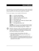
2-3 Installation Guide
We will now begin the installation of the mainboard. Please follow
the step-by-step procedure designed to lead you to a complete and
correct installation.
Step 1. CPU Installation
Follow these instructions to install your Pentium
®
class processor
correctly.
Locate the CPU socket labeled Socket 7 on your mainboard and
note the distinctive pinhole arrangement.
Note the corresponding pinhole arrangement on the processor.
CPU
Socket 7
Blunt Edge Blunt Edge

Introduction SY-5EMM
9
Follow these steps to install the CPU in the Socket 7:
1. Lift the socket handle up to a vertical position.
2. Align the blunt edge of the CPU with the matching pinhole
distinctive edge on the socket.
3. Seat the processor in the socket completely and without forcing.
4. Then close the socket handle to secure the CPU in place.
Step 2. CPU Fan Installation
Your Pentium
®
processor kit comes with a cooling fan. Mount the fan
on the processor according to the instructions provided by the
manufacturer. The fan is a key component that will ensure system
stability. The fan prevents overheating, therefore prolonging the life
of your CPU.
Note: Remember to connect the fan to the appropriate power
source.
1 2
3 4

Introduction SY-5EMM
10
Step 3. CPU Voltage Setting (JP30,JP1 and JP2)
Please verify the correct voltage with your dealer before installation.
Use the following tables to set JP30 to the proper "Voltage Value",
according to the specifications marked on your CPU: This
mainboard comes with pre-configured setting of CPU voltage.
However the voltage of your CPU maybe different with the default
setting.
l CPU VOLTAGE SETTING (JP30,JP1 and JP2)
JP30 is used to set the CPU core voltage, JP1 and JP2 are used to
select the CPU voltage type single voltage or dual voltage.
There are two kinds of CPU voltages currently on the market
depending on the CPU manufacturer:
Ø Single Voltage (CPU: P54C, AMD-K5, Cyrix 6x86)
Ø Dual Voltage (CPU: P55C, AMD-K6, AMD-K6-2 Cyrix
6x86L,Cyrix 6x86MX, Cyrix M II)
*
Flash BIOS
JP30
JP1 JP2
CPU Voltage
Single or Dual
Voltage Selection
1
3
5
7
2
4
6
8

Introduction SY-5EMM
11
Those processors may come in various voltages on different
markets. Therefore, always make sure you know the type of the
CPU you are installing and adjust the settings on JP30 accordingly.
This motherboard supports CPU core voltages from 2.0 to 3.52V in
0.1V increments. Use the following tables to set the CPU voltage
jumpers JP30 to match the voltage value of your CPU:
CPU Core Voltage Setting: JP30
Voltage Value 1-2 3-4 5-6 7-8
3.5V close close close close
3.4V open close close close
3.3V close open close close
3.2V open open close close
3.1V close close open close
3.0V open close open close
2.9V close open open close
2.8V open open open close
2.7V close close close open
2.6V open close close open
2.5V close open close open
2.4V open open close open
2.3V close close open open
2.2V open close open open
2.1V close open open open
2.0V open open open open
Single or Dual voltage selection: JP1 and JP2
Voltage Type JP1 JP2
Single Voltage
(P54C, AMD-K6, Cyrix 6x86)
Dual Voltage
(P55C, AMD-K6, AMD-K6-2, Cyrix
6x86L, Cyrix 6x86MX, Cyrix M II)

Introduction SY-5EMM
12
Voltage Settings for Various Processors
Processor
Voltage Setting
Voltage Value: JP30 JP1 JP2
Intel P54C - P100
Intel P54C - P133
Single Voltage
VORE:3.3V
VI/O:3.3V
Intel P54C - P166
Intel P54C - P200
Single Voltage
VORE:3.5V
VI/O:3.5V
Intel P55C - P166
Intel P55C - P200
Intel P55C - P233
Dual Voltage
VORE:2.8V
VI/O:3.3V
AMD K5 - PR100
AMD K5 - PR133
AMD K5 - PR166
Single Voltage
VORE:3.5V
VI/O:3.5V
AMD K6 166
AMD K6 200
Dual Voltage
VORE:2.9V
VI/O:3.3V
AMD K6 233
Dual Voltage
VORE:3.2V
VI/O:3.3V
AMD K6 266
AMD K6 300
AMD K6-2 266
AMD K6-2 300
AMD K6-2 333
AMD K6-2 350
Dual Voltage
VORE:2.2V
VI/O:3.3V
1
3
5
7
2
4
6
8
1
3
5
7
2
4
6
8
1
3
5
7
2
4
6
8
1
3
5
7
2
4
6
8
1
3
5
7
2
4
6
8
1
3
5
7
2
4
6
8
1
3
5
7
2
4
6
8

Introduction SY-5EMM
13
Voltage Settings for Various Processors (continued)
Processor
Voltage Setting
Voltage Value: JP30 JP1 JP2
Cyrix 6x86(L) PR166+
Cyrix 6x86(L) PR200+
The Cyrix 6x86(L) come in several versions
with different voltages. Please ask your
dealer for the correct voltage.
Cyrix 6x86MX-PR166*
Cyrix 6x86MX-PR200*
Cyrix 6x86MX-PR233*
Cyrix 6x86MX-PR266*
Cyrix M II 300*
Cyrix M II 333*
Cyrix M II 350*
Dual Voltage
VORE:2.9V
VI/O:3.3V
* Set the proper CPU voltage according to the marking on the CPU.
1
3
5
7
2
4
6
8

Introduction SY-5EMM
14
Step 4. CPU Frequency Setting (SW1)
The SY-5EMM mainboard is designed to support most Pentium
®
class processors currently on the market. Jumpers SW1 is used to
configure the mainboard frequency parameters to match the
working frequency of your CPU.
*
Flash BIOS
Host Bus Frequency
Frequency Multiplier
1
6
5
4
3
2
1
6
5
4
3
2

Introduction SY-5EMM
15
l CPU FREQUENCY SETTING (SW1)
Configure the SW1 jumpers to the settings that match your CPU
speed. Refer to the following tables to set the Frequency Multiplier
and Host Bus Frequency of your CPU:
Frequency Multiplier Host Bus Frequency
Multiplier 1 2 3
Host Bus
Frequency
4 5 6
1.5/3.5x off off off 66MHz off off off
2.0x* on off off 75MHz off on off
2.5x on on off 83MHz on on off
3.0x off on off 95MHz on off on
4.0x on off on 100MHz off off on
4.5x on on on 112MHz off on on
5.0x off on on 124MHz on off off
Example: If the working frequency of your CPU is 133MHz, then
select Multiplier=2.0x and Host Bus Frequency=66Mhz accordingly.
Also, as newer and higher frequency CPUs may not be listed in this
section, please refer to the tables CPU Frequency Settings for
Various Processors on page 8 for complementary information.

Introduction SY-5EMM
16
Please refer to the following table that gives you the correct
frequency settings for the specific brand and model of CPU you are
installing on this mainboard.
Frequency Settings for Intel
®
Processors
Processor
Frequency Setting
Ratio
Bus
Clock
AGP
Clock
PCI
Clock
Frequency
Setting: SW1
Intel P54C - P100 1.5 x 66MHz 66MHz 33MHz
Intel P54C - P133 2.0 x 66MHz 66MHz 33MHz
Intel P54C - P166 2.5 x 66MHz 66MHz 33MHz
Intel P54C - P200 3.0 x 66MHz 66MHz 33MHz
Intel P55C - P166 2.5 x 66MHz 66MHz 33MHz
Intel P55C - P200 3.0 x 66MHz 66MHz 33MHz
Intel P55C - P233 3.5 x 66MHz 66MHz 33MHz
* Set the proper CPU frequency according to the marking on the CPU.
1
2
3
4
5
6
ON
1
2
3
4
5
6
ON
1
2
3
4
5
6
ON
1
2
3
4
5
6
ON
1
2
3
4
5
6
ON
1
2
3
4
5
6
ON
1
2
3
4
5
6
ON

Introduction SY-5EMM
17
Frequency Settings for AMD™ Processors
Processor
Frequency Setting
Ratio
Bus
Clock
AGP
Clock
PCI
Clock
Frequency
Setting: SW1
AMD K5 - PR100 1.5 x 66MHz 66MHz 33MHz
AMD K5 - PR133 2.0 x 66MHz 66MHz 33MHz
AMD K5 - PR166 2.5 x 66MHz 66MHz 33MHz
AMD K6 - 166 2.5 x 66MHz 66MHz 33MHz
AMD K6 - 200 3.0 x 66MHz 66MHz 33MHz
AMD K6 - 233 3.5 x 66MHz 66MHz 33MHz
AMD K6 - 266 4.0 x 66MHz 66MHz 33MHz
AMD K6 - 300 4.5 x 66MHz 66MHz 33MHz
AMD K6-2 266 4.0 x 66MHz 66MHz 33MHz
AMD K6-2 300 3.0 x 100MHz 66MHz 33MHz
AMD K6-2 333 3.5 x 95MHz 63.4MHz 31.7MHz
AMD K6-2 350 3.5 x 100MHz 66MHz 33MHz
* Set the proper CPU frequency according to the marking on the CPU.
1
2
3
4
5
6
ON
1
2
3
4
5
6
ON
1
2
3
4
5
6
ON
1
2
3
4
5
6
ON
1
2
3
4
5
6
ON
1
2
3
4
5
6
ON
1
2
3
4
5
6
ON
1
2
3
4
5
6
ON
1
2
3
4
5
6
ON
1
2
3
4
5
6
ON
1
2
3
4
5
6
ON
1
2
3
4
5
6
ON
/