Page is loading ...

IP-7000TXWP
HDMI or VGA Video Wall late Transmitter
(4K) over IP/CEC/PoE
OPERATION MANUAL

®
registered trademarks of HDMI licensing Administrator, Inc.

DISCLAIMERS
The information in this manual has been carefully checked and is
believed to be accurate. CYP (UK) Ltd assumes no responsibility for any
infringements of patents or other rights of third parties which may result
from its use.
CYP (UK) Ltd assumes no responsibility for any inaccuracies that may be
contained in this document. CYP (UK) Ltd also makes no commitment to
update or to keep current the information contained in this document.
CYP (UK) Ltd reserves the right to make improvements to this document
and/or product at any time and without notice.
COPYRIGHT NOTICE
No part of this document may be reproduced, transmitted, transcribed,
stored in a retrieval system, or any of its part translated into any language
or computer le, in any form or by any means—electronic, mechanical,
magnetic, optical, chemical, manual, or otherwise—without express
written permission and consent from CYP (UK) Ltd.
© Copyright 2020 by CYP (UK) Ltd.
All Rights Reserved.
Version 1.1
TRADEMARK ACKNOWLEDGMENTS
All products or service names mentioned in this document may be
trademarks of the companies with which they are associated.

SAFETY PRECAUTIONS
Please read all instructions before attempting to unpack, install or operate
this equipment and before connecting the power supply.
Please keep the following in mind as you unpack and install this
equipment:
• Always follow basic safety precautions to reduce the risk of re,
electrical shock and injury to persons.
• To prevent re or shock hazard, do not expose the unit to rain,
moisture or install this product near water.
• Never spill liquid of any kind on or into this product.
• Never push an object of any kind into this product through any
openings or empty slots in the unit, as you may damage parts inside
the unit.
• Do not attach the power supply cabling to building surfaces.
• Use only the supplied power supply unit (PSU). Do not use the PSU if
it is damaged.
• Do not allow anything to rest on the power cabling or allow any
weight to be placed upon it or any person walk on it.
• To protect the unit from overheating, do not block any vents or
openings in the unit housing that provide ventilation and allow for
sucient space for air to circulate around the unit.
REVISION HISTORY
REV. DATE SUMMARY OF CHANGE
v1.00 2020/05/07 Preliminary release (RDV1)

CONTENTS
1. Introduction .................................................. 1
2. Applications ..................................................1
3. Package Content ...........................................2
4. System Requirements ..................................2
5. Features ......................................................... 3
6. Operation Controls and Functions ..............4
6.1 Front Panel .............................................................4
6.2 Rear Panel ...............................................................6
6.3 IR Cable Pinouts ...................................................7
6.4 RS-232 Pinout and Defaults .............................7
6.5 WebGUI Control ...................................................8
6.5.1 System Tab ...............................................10
6.5.2 Video Wall Tab ......................................... 14
6.5.3 Network Tab............................................. 18
6.5.4 Functions Tab .......................................... 20
6.6 Telnet Control ..................................................... 24
6.7 Telnet Commands ............................................ 24
7. Connection Diagram ..................................34
8. Specications .............................................. 35
8.1 Technical Specications ................................. 35
8.2 Video Specications......................................... 36
8.3 Audio Specications ........................................38
8.3.1 Digital Audio ...........................................38
8.3.2 Analogue Audio ..................................... 39
8.3.3 AVoIP Audio Availability ...................... 39
8.4 Cable Specications ........................................ 41
9. Acronyms .....................................................42

1
1. INTRODUCTION
The AVoIP wall plate transmitter forms a part of a 4K UHD multi-function
extension system that is able to extend HDMI or VGA signals along with
analogue audio, USB 2.0, IR and serial data using the TCP/IP protocol over
regular Gigabit Ethernet networks. When using standard Ethernet cables,
this system supports the extension of AVoIP signals up to 100 meters and
the extension distance can be further extended (up to 100m per segment)
by using gigabit network switches. This allows the user to cascade the
system without signal loss or introducing delay. The USB functionality
allows the system to act like a remote USB hub which provides a exible
remote KVM platform.
When the extension system's units are in multicast mode, a single AV
signal can be sent to a large number of receivers within the same local
network without the additional receivers increasing the bandwidth
requirements. Additionally, that same multicast signal can be used to
create large multi-display video walls with amazing simplicity. When
combined with the optional IP Master Controller the functionality of the
system expands exponentially. Its centralised web-based interface greatly
simplies control and management of large distributed video matrix or
video wall systems adding to their exibility in large home or commercial
installations.
Configuration information is provided via OSD (On Screen Display) and
control is via WebGUI, Telnet or the IP Master Controller (Optional).
2. APPLICATIONS
HDMI, VGA, USB, Audio, IR, and RS-232 extension
Multimedia display on a large number of displays via multicast
Hotel or convention center display multi-monitor broadcast
Long distance data and video transmission via cascading
Distributed video matrix system
Distributed video wall system
Remote KVM control of a system

2
3. PACKAGE CONTENT
1× UHD Video over IP Transmitter
1× IR Extender Cable
1× IR Blaster Cable
1× Operation Manual
4. SYSTEM REQUIREMENTS
HDMI or VGA source equipment such as media players, video game
consoles, PCs, or set-top boxes.
Analogue audio receiving equipment such as headphones, audio
ampliers or powered speakers.
A Gigabit Ethernet network switch with PoE (802.3af or better) and
jumbo frame support is required. (8K jumbo frames are strongly
recommended.)
A Gigabit Ethernet switch with “IGMP snooping” enabled is required for
multicast support.

3
5. FEATURES
HDMI 2.0 and DVI 1.0 compatible
HDCP 1.4 & 2.2 compliant
1 HDMI input & 1 VGA input
Video, audio and control transmission over TCP/IP in Unicast (point-to-
point) or Multicast (single-to-many) modes
HDMI input supports resolutions up to 4K@60Hz (4:2:0, 8-bit) or
4K@30Hz (4:4:4, 8-bit)
Note: 4K@50/60Hz (YUV 4:2:0) sources are automatically converted to
4K@25/30Hz (RGB) prior to transmission
VGA input supports resolutions up to WUXGA(RB)
Supports the extension of many audio formats including 8 channel
LPCM and Bitstream
Supports generating video walls consisting of up to 16 displays
By default, the analogue Line In is automatically embedded in the
streaming output when the VGA input is selected
The Mic In on a linked receiver sends audio directly to the analogue
Line Out on the transmitter
Powered directly by PoE (802.3af ) from the connected Gigabit Ethernet
switch
Supports USB host device extension allowing the remote connection
of a keyboard, mouse or storage
Supports IR and RS-232 bypass
Supports automatic input switching on signal loss
Unit can be controlled via WebGUI and Telnet, and supports the use of
an external control center (IP Master Controller) to provide expanded
functionality (Contact your authorised dealer for more information)

4
6. OPERATION CONTROLS AND FUNCTIONS
6.1 Front Panel
IR LINE
IN INOUTOUT
SOURCE
RS-232
HDMI IN
VGA IN
USB
LINK POWER
IP-7000TXWP
1 2 3 4 5 6
7 8 9 10 11
1
USB 2.0 (Type-B) Port: Connect directly to a PC, or other USB host
device, to extend its USB functionality to the ports on the connected
receiver.
2
RS-232 Port: Connect directly to your PC/laptop to send commands
to RS-232 devices connected to the linked receiver. The baud rate is
congurable, but the default baud rate is 115200.
Note: When the transmitter is in multicast mode every connected receiver
unit can send RS-232 commands to the transmitter and commands sent
from the transmitter side will be sent to all associated receivers.
3
SOURCE LED: This LED will illuminate red when an HDMI source is live
and green when a VGA source is live. If no live sources are detected,
this LED will remain o.
4
LINK LED: If the transmitter has no network connection the LINK LED
will not illuminate. While the transmitter is attempting to establish
a connection with a receiver the LINK LED will ash. When the
transmitter has established a stable connection with a receiver the
LINK LED will illuminate solidly.

5
5
POWER LED: This LED will ash while the unit is powering on and will
illuminate solidly once it is ready to be used.
6
HDMI IN Port: Connect to HDMI source equipment such as a media
player, game console or set-top box.
7
IR IN Port: Connect to the provided IR Extender to extend the IR
control range of remotely located devices. Ensure that the remote
being used is within direct line-of-sight of the IR Extender.
Note: When the transmitter is in multicast mode the IR signal is sent to all
associated receivers.
8
IR OUT Port: Connect to the provided IR Blaster to transmit IR signals
sent from the associated receiver to devices within direct line-of-sight
of the remote IR Blaster.
9
LINE IN Port: Connect to the stereo analogue output of a device such
as a CD player or PC.
Note: By default, the analogue Line In is automatically embedded with
the VGA input in the streaming output.
10
LINE OUT Port: Connect to powered speakers or an amplier for
stereo analogue audio output. This will output the audio from the Mic
In on the connected receiver.
Note: This function is only available in unicast mode. The Mic In audio
channel from the receiver is only active when an analogue source is also
connected to the Line In port on the transmitter.
11
VGA IN Port: Connect to VGA source equipment such as a PC or
laptop.

6
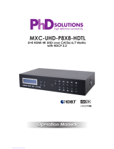
6.2 Rear Panel
CAT5e/6/7
OUT
3
1
CAT5e/6/7 OUT Port: Connect via a Gigabit Ethernet switch to
compatible receiver(s) to transmit data, and to a PC/laptop to control
the unit via WebGUI.
Note: This unit is powered directly by the PoE from the connected Gigabit
Ethernet switch (802.3af minimum).

7
6.3 IR Cable Pinouts
IR Blaster
Cable
1
2
3
Infrared
Power
Not Used
IR Extender
Cable
1
2
3
Infrared
Power
Ground
6.4 RS-232 Pinout and Defaults
Serial Port Default Settings
Baud Rate 115200
Data Bits 8
Parity Bits None
Stop Bits 1
Flow Control None
1
2
3
4
5
8
7
6
9
DCD
RxD
TxD
DTR
GND
RI
CTS
RTS
DSR
DE-9 Female Port

8
6.5 WebGUI Control
Device Discovery
Please obtain the “Device Discovery” software from your authorised dealer
and save it in a directory where you can easily nd it.
Connect the unit and your PC/Laptop to the same active network and
execute the “Device Discovery” software. Click on “Find Devices on
Internet” and a list of devices connected to the local network will show up
indicating their current IP address.
Note: The default network setting for this unit is “Auto IP”.
By clicking on one of the listed devices you will be presented with the
network details of that particular device.
1) IP Mode: If you choose, you can alter the static IP network settings for
the device, or switch the unit into DHCP mode to automatically obtain
proper network settings from a local DHCP server. To switch to DHCP
mode, please select DHCP from the IP mode drop-down, then click
“Save” followed by “Reboot”.
2) WebGUI Hotkey: Once you are satised with the network settings, you may
use them to connect via Telnet or WebGUI. The network information window
provides a convenient link to launch the WebGUI directly.

9
WebGUI Overview
All major functions of this unit, including status, streaming method,
streaming channel selection, output resolution, video wall configuration,
EDID management, Ethernet settings, and reset/firmware functions
are controllable via multiple tabs in the WebGUI interface allowing for
reasonably intuitive operation.
Each transmitter, receiver, or transceiver in the system is controlled by its
own WebGUI interface which may be accessed by opening a standard
web browser on a PC and typing in the IP address of the unit you wish to
connect to. The easiest way to obtain each unit’s IP address is to use the
Discovery Tool software.
On a transceiver unit, the IP address of a unit can be obtained simply
by checking the information screen within the OSD menu, accessed by
pressing the menu button.
Alternatively, on stand-alone transmitters/receivers you can discover
the IP address by checking the status OSD that is displayed when there
is no live video source or no live link. Breaking the link is accomplished
by pressing and holding the “LINK” button on the front of the currently
associated receiver for 3 seconds (The LINK light will blink rapidly, then
turn off). Once the link is broken, each connected receiver will output a
640×480 black screen with OSD text at the bottom identifying its own IP
address (Local IP), as well as the IP address of the transmitter (Remote IP)
that shares the same broadcasting channel with it (channel 0 by default).
After obtaining the IP address information, press and hold the “LINK”
button on the receiver again for 3 seconds to return the units to normal
operation (The LINK light will light up solid yellow).
After connecting to a unit’s WebGUI, you will find a screen containing
multiple tabs for each functionality area of the unit.
Note: AVoIP streaming uses a large amount of bandwidth (especially at higher
resolutions) and a Gigabit Ethernet network switch with jumbo frame support
and IGMP snooping is required. A professional managed switch with VLAN
support is strongly recommended. Please note that most consumer-grade
routers are not able to handle the high traffic rates generated by multicast
mode, so using a router directly as your network switch is discouraged. It is
strongly suggested to avoid mixing your regular network traffic with AVoIP

10
streaming traffic and the AVoIP traffic should exist within a separate subnet,
at the minimum.
6.5.1 System Tab
The System tab contains 4 windows that provide access to rmware
version information, a rmware update interface, utilities for rebooting
and resetting the unit, basic EDID management, Telnet command entry,
and a variety of statistics and information about the operational state of
the unit.
1) Version Information Window: This window displays detailed
information about the current rmware version.
2) Update Firmware Window: Provides a way to update the transmitter’s
rmware. Click “Choose File” to select the rmware update le from
the local PC (*.bin format). After selecting an appropriate le, click the
“Upload” button to begin the update process.

11
3) Utilities Window: The Utilities window allows users to reset the unit
back to the factory defaults by clicking “Factory Default”. The unit may
be rebooted (without resetting settings) by pressing the “Reboot”
button. If requested by technical support, you may also enable
logging by clicking the “Log Message” checkbox.
If the EDID received from the primary receiver unit (selected via
a checkbox on the preferred receiver in multicast mode) has
compatibility issues with the connected source, a basic internal HDMI
EDID (up to 4K30 w/audio) or basic VGA EDID can be selected. Please
press “Apply” after making the selection.
Note: This EDID setting will be reset if the unit is rebooted.
Finally, individual Telnet commands may be sent to the unit by using
the “Console API Command” text entry eld and pressing “Apply”. Any
responses from the unit will be displayed in the “Output” eld.

12

13
4) Statistics Window: The Statistics window shows all available
information about the operational status of the unit, including the
current host name, serial number, Ethernet information, MAC address,
unicast/multicast mode, and link status and mode.

14
6.5.2 Video Wall Tab
The Video Wall tab allows user to design, edit and manipulate a video
wall system created using multiple receiver units connected to identical
displays. The bezel and video size of the displays being used, as well as
the horizontal and vertical monitor count, is dened here. Video stretch
and rotation can also be controlled on this tab. Receivers in the video
wall’s group (all receivers sharing the same channel) can be controlled by
any other unit within the same group.
Note: While the Video Wall tab is accessible on transmitters, video wall
settings only have an eect on receivers.
When saving changes on the Video Wall tab, remember to select the
appropriate “Apply To:” target unit before pressing the “Apply” button.
Select the IP address of the receiver (Client) you want to apply changes to
from the “Apply To:” drop down.
Note: While it is possible to create small video walls using unicast mode, in
order to more eciently use the available network bandwidth, it is strongly
recommended to only use multicast mode when creating video walls.
1) Bezel and Gap Compensation: This section of the Video Wall tab
is used to dene the physical dimensions of each display being
used in the video wall. Accurate measurements are needed of the
monitor’s outer frame (OW, OH) and the video screen (VW, VH). The
measurements may be made using any unit format (inches, mm, cm,
etc.) as long as ALL measurements in the same wall are made using
the exact same units and the numbers are integers.

15
OW (Outer Width): This is the horizontal measurement of the
display’s outer case.
OH (Outer Height): This is the vertical measurement of the
display’s outer case.
VW (Video Width): This is the horizontal measurement of the
display’s video screen.
VH (Video Height): This is the vertical measurement of the display’s
video screen.
Note: Typically all monitors in a video wall are identical and have the
same dimensions, but it is possible to use dierently sized displays as
long as the same measurement units are used to measure each display
and the displays are still arranged in a normal rectangular layout with
corners meeting at the same place.
Apply To: Select which unit(s) to send updated settings to when
“Apply” is pressed.
- Selecting “All” will direct updates to the video wall bezel settings
of all units in the current video wall group.
- Selecting an IP address from the “Clients” list will direct updates to
the video wall settings of the receiver with that IP address.
/