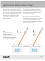
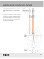
C.Scope M-Scan is a magnetic locator used to detect buried ferrous metal objects. With eight sensitivity settings and a depth range of up to 6 meters, it is a versatile tool for treasure hunting, archaeology, and utility detection. The M-Scan can differentiate between ferrous and non-ferrous metals, and it can also be used to trace the path of buried pipes and cables.
C.Scope M-Scan is a magnetic locator used to detect buried ferrous metal objects. With eight sensitivity settings and a depth range of up to 6 meters, it is a versatile tool for treasure hunting, archaeology, and utility detection. The M-Scan can differentiate between ferrous and non-ferrous metals, and it can also be used to trace the path of buried pipes and cables.


-
 1
1
-
 2
2
-
 3
3
-
 4
4
-
 5
5
-
 6
6
-
 7
7
-
 8
8
-
 9
9
-
 10
10
-
 11
11
-
 12
12
-
 13
13
-
 14
14
-
 15
15
-
 16
16
-
 17
17
-
 18
18
-
 19
19
-
 20
20


C.Scope M-Scan is a magnetic locator used to detect buried ferrous metal objects. With eight sensitivity settings and a depth range of up to 6 meters, it is a versatile tool for treasure hunting, archaeology, and utility detection. The M-Scan can differentiate between ferrous and non-ferrous metals, and it can also be used to trace the path of buried pipes and cables.
Ask a question and I''ll find the answer in the document
Finding information in a document is now easier with AI


Other documents
-
C-SCOPE Cable Avoidance Tool User manual
-
-
-
C-SCOPE SGA4 User manual
-
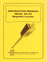 SCHONSTEDT GA-52 Owner's manual
-
 Schonstedt Instrument GA-72Cd User manual
-
 Magswitch 8110004 User manual
-
GEM GSM-19 User manual
-
 Bounty Hunter Gold Owner's manual
-
 Magnaflux Universal 320 SW Operating instructions


