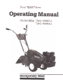
Montgomery Ward TMO-39083A User manual
- Category
- Mini tillers
- Type
- User manual
This manual is also suitable for


11
11
14
16,18,20,21,22
.17,18,19,20,21,22
BackCover
Safe Operation Practices. Assembly. Controls. Operation. How To UseY our Tiller Adjustments.
Instructions given with this symbol are for per.
sonal safety. Be sure to follow them.
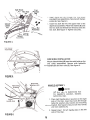
NOTICE: A data plate with the model number and serial numbers of your unit is located on the tine shield.
Record these numbers in the spaces provided on the back cover of this guide.
Check Spark Plug Wire
.Firmly attached?
.Wire terminal clean?
Check Crankcase Oil Level
.Overfilled/underfilled?
Check Fuel Tank
.Fuel in tank?
.Fuel dirty or stale?
.If tank has been empty for a long period,
fill tank completely.
Check Air Cleaner
.Clean?
.Choke plate stuck?
.Governor spring free to move?
Check Starting Instructions
.Read instruction manuals and labels for specific
instructions.
* WARNING ~
::c-'
This unit is equipped with an internal combustion engine and should not be used on or near any unim-
proved forest-covered, brush-covered or grass-covered land unless the engine's exhaust system is
equipped with a spark arrester meeting applicable local or state laws (if any). If a spark arrester is used, it
should be maintained in effective working order by the operator.
In the State of California the above is required by law (Section 4442 of the California Public Resources
Code). Other states may have similar laws. Federal laws apply on federal lands. A spark arrester muffler is
available at your nearest engine authorized service center.
2
...3 Lubrication ...4 Maintenance. ...8 Off-Season Storage
...9 Illustrated Parts ...
...9 PartsList ..10 Parts Information. .

,
~ WARNING ~
'
To reduce the potential for any injury, comply with the following safety instructions. Failure to comply with
the instructions may result in personal injury.
1. It is suggested that this manual be read in its
entirety before attempting to assemble or
operate this unit. Keep this manual in a safe
place for future reference and for ordering
replacement parts.
14. Do not walk in front of the tiller while the
engine is running.
15. Check the fuel before starting the engine.
Gasoline is an extremely flammable fuel. Do
not fill gasoline tank indoors, when the engine
is running, or while the engine is still hot.
Wipe off any spilled gasoline before starting
the engine as it may cause a fire or explosion.
2. Your tiller is a precision piece of power equip-
ment, not a plaything. Therefore, exercise ex-
treme caution at all times.
3. Read this Owner's Manual carefully. Be
thoroughly familiar with the controls and the
proper use of the equipment.
16. Do not run the engine while indoors. Exhaust
gases are deadly poisonous.
17. Be careful not to touch the muffler after the
engine has been running. It is hot.
4. Never allow children to operate a power tiller.
Only persons well acquainted with these rules
of safe operation should be allowed to use
your tiller.
18.
Do not change the engine governor settings
or overspeed the engine. Excessive engine
speeds are dangerous.
5. No one should operate this unit while intoxi-
cated or while taking medication that impairs
the senses or reactions.
19. Before any maintenance work is performed or
adjustments are made, remove the spark plug
wire and ground it on the engine block for
added safety.
6.
Keep the area of operation clear of all per-
sons, particularly small children and pets.
7. Do not operate equipment when barefoot or
wearing open sandals. Always wear substan-
tial footwear.
20. Use caution when tilling near buildings and
fences. Rotating tines can cause damage or
injury.
8. Do not wear loose fitting clothing that could
get caught on the tiller.
21. Before attempting to remove rocks, bricks and
other objects from tines, stop the engine and
be sure the tines have stopped completely.
Disconnect the spark plug wire and ground to
prevent accidental starting.
9. Do not start the engine unless the shift lever
is in the neutral (N) position.
10. Do not stand in front of the tiller while starting
the engine.
22.
Check the tine and engine mounting bolts at
frequent intervals for proper tightness.
11. Do not place feet and hands on or near the
tines when starting the engine or while the
engine is running.
23. Keep all nuts, bolts and screws tight to be
sure the equipment is in safe working condi-
tion.
12. Never attempt to make a wheel or depth bar
adjustment while the engine is running.
24. Never store the equipment with gasoline in
the tank inside of a building where fumes may
reach an open flame or spark. Allow the
engine to cool before storing in any
enclosure.
13.
Do not leave the tiller unattended with the
engine running.
3

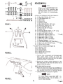
ASSEMBLY
o-J1
E-i
c
NOTE
This unit is shipped WITHOUT GAS-
OLINE or OIL. After assembly, see
separate engine manual for proper
fuel and engine oil recommenda-tions.
:jlllR-ir .,
H-@ @ @ @S--@JN-@@~~
I ~ @ @ @ T- e o-@ ~ @ ~
L
, U--@
v ---~ p (:!;)(~~ ~
Q-~@@@
FIGURE 1.
AE
~Contents of Hardware Pack: (See Figure 1)
A (1) Hex Bolt 3/8-16 x 3/4" Long
B (1) Flat Washer 3/8" I.D.
C (1) Ball Knob
D (1) Clevis Pin
E (1) Hairpin Cotter
F (4) Hex Bolts 3/8-16 x 1.0" Long
G (4) Belleville Washers 3/8" I.D.
H (4) Lock Washers 3/8" I.D.
I (4) Hex Nuts 3/8-16 Thread
L (2) Cable Ties
M (4) Carriage Bolts 5/16-18 x 1.75" Long
N (4) Lock Washers 5/16" I.D.
0 (4) Hex Nuts 5/16-18 Thread -'=- -
P (4) Belleville Washers 5/16" I.D. --=.:;..-::
Q (4) Hex Nuts 5/16-18 Thread
R (1) Hex Bolt 1/4 -28 x 1" Long
S (1) He~Lqck Nut 1/4-28 Thread
T (1) Rubber Washer,~~_-
U (1) Flat Washer 5/16" I.D. X7/8~r-.o.Q=:.:: V (1) Hex Lock Nut 5/16-18 Thread --.
W (1) Drive Clutch Lever--Loose
Parts in Carton: (See figure 2)
AA (1) Handle-R.H.
AB (2) Side Shields
AC (1) Handle Panel
AD (1) Depth Bar Assembly
AE (1) Handle-L.H.
""----
FIGURE 2.
1. Remove tiller, loose parts and hardware pack
from carton. Make certain all parts and
literature have been removed from the carton
before the carton is discarded.
2. Extend the control cables attached to the
ti!ler and place on the floor. Be careful not to
bend or kink the cables.
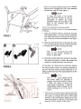
DEPTH BAR INSTAllATION
1. Raise the tine shield hinge flap assembly. )p-
sert the depth bar assembly (AD) between the
two shoulder bolts and up through the tin~-shield
assembly as shown in figure 3.
NOTE
."
For clarity, figure 3 was taken with., "-.-:"",,,~:
tiller raised on end. It is not neces~~;:
sary to raise the tiller. .:
FIGURE 3.
~~,~;;';
4

Flat
Washer
-(8)
Ball Knob
(C) Hex Bolt
(A)
~
I
~
e~
#)
Depth Bar
Assembly
--.
~
~
Hairpin
Cotter'
(E) ,
2.
Insert clevis pin (0) through the tine shield
and depth bar assemblies. Secure with hairpin~cotter
(E). See figure 4.
3. Insert hex bolt (A) into the upper hole of the
depth bar assembly. Place flat washer (8) onto
the hex bolt and thread ball knob (C) onto the
hex bolt. See figure 4. Tighten securely.
Clevis
Shield Pin (0)
Assembly
11
FIGURE 4.
SIDE SHIELD INSTALLATION
Mount s,de shields (AB) over the weld bolts on the
end cover assemblies. Secure with belleville
-washers (P) and hex nuts (Q). See figure 5.
FIGURE 5.
HANDLE ASSEMBLY
NOTE
Left and right is determined from
the operator's position, standing
behind the tiller.
1. Place right handle (AA) in position on the right
side of the tiller. Insert hex bolts (F) through
belleville washers (G), handle and mounting
4 bracket. See figure 6. Secure with hex nuts (I)
and lock washers (H).
2. Repeat step 1 for left handle (AE) on the left
side of the tiller.
FIGURE 6
5

3.
Mount the handle panel (AC) to the handles.
Secure with carriage bolts (M), lock washers
-(N) and hex nuts (0). See figure 7.
NOTE
To align the holes in the handle
panel and the handle, it may be
necessary to loosen the cable
brackets which are mounted to the
back of the handles with self-
tapping screws.
FIGURE 7.
THROTTLE CONTROL INSTAllATION
Assemble the throttle control to the handle panel
as follows.
1. Hold the throttle control assembly beneath
the handle panel. Turn the control sideways
and insert the lever up through the wide por-
tion of the slot on the handle panel. See figure
8A.
2. After the end of the lever is through the slot,
turn and then tip the control forward as shown
-in figure 88 to slide it through the slot.
IAI
NOTE
The lever must be all the way to the
back of the control housing as
shown in figure 88.
3. Push the control back into the slot in the han-
dle panel and press in place. Be certain the
control is locked securely into the slot.
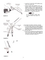
ATTACHING THE TINE CLUTCH CONTROL CABLE
The clutch control cables are already attached to
the unit. The tine clutch control cable has a "Z"
fitting on the loose end. This cable attaches to the
left handle.
FIGURE 8.
NOTE
Both the drive clutch cables and the
tine clutch cable are attached tosprings,
which are hooked to bolts.
If either the cable or spring has
come loose in shipping, it must bereassembled.
Refer to page 18, ref-
erence numbers 2, 5,11,12,15,17
and 21.
1.
Remove one nut and the lock washer from the
end of the tine clutch cable (short cable). Slip
the cable up through the slot on the cable
bracket on the left handle. Rethread hex nut
and lock washer on the end of the cable. See-figure
9. Do not tighten at this time.
6

2. Hook the "Z" end of tine clutch cable into the
hole in tine clutch lever.
3. With the clutch lever released (in the "up"
position), adjust the bottom nut at the cable
bracket so there is only a slight amount of
slack in the control wire. Tighten the upper
nut against the bracket. Squeeze the clutch
lever against the handle. The control wire
~should now be straight. See figure 10.
NOTE
Do not overtighten control wire.
Too much tension may cause it to
break.
FIGURE 10.
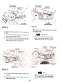
ATTACHING THE DRIVE CONTROL CABLES
1. The drive clutch cables are already attached
to the unit. Attach the other end of cables to
the upper hole of drive clutch lever (W), one on
each side, using hex bolt (R) and hex lock nut
~(S). See figure 11.
2. Remove one nut and the lock washer from the
end of each drive clutch cable. Thread the
other hex nut all the way down the cable as far
as it will go as shown in figure 11.
FIGURE 11.
~J
FIGURE 12.
7

6. Secure drive clutch lever to weld bolt with rub-
ber washer (T), flat washer (U) and hex lock nut.,(V).
See figure 13. Tighten hex nut.
7. Place the drive clutch lever in the neutral (N)
position. Adjust the cables at the cable
bracket so that the cables are tight, then
tighten the hex nuts against the cable
bracket.
FIGURE 13.
IMPORTANT
Service engine with oil and gasoline
before checking the drive clutch
adjustment. Refer to the separate
engine manual packed with your
tiller.
8. Check the adjustment of the drive clutch as
follows. Place the unit against a solid object
(wall, fence, etc.). With the tine clutch lever
released and the drive clutch lever in the
neutral position, carefully start the engine. If
the unit shows any signs of motion with the
drive clutch lever in neutral, shut the engine
off immediately and readjust the hex nuts at
the cable bracket. Recheck the adjustment as
necessary .
9. Secure the cables to the handles as with cable
ties (L). Cut off excess ends of cable ties.
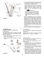
CONTROLS-Location and Use
Tine Clutch Lever
The tine clutch lever is located on the left handle.
See figure 14.
Squeeze the lever down to engage the tines.
Release the lever to disengage the tines.
Throttle Control
The throttle control lever is located on the right
hand side of handle panel and controls the engine
speed. See figure 14.
1. Start-Push throttle control lever forward
(down) to start position.
2. Stop-Pull lever back (upward) to stop the
engine.
Tine
Clutch
Lever
Drive
Clutch
Lever
~~
O\
Drive Clutch Lever
The drive clutch lever is located on the left hand
side of handle panel. See figure 14.
The drive clutch lever may be placed in one of
three positions.
1. Forward (F)-Move the drive clutch lever to
the left and all the way forward to engage the
drive mechanism to the wheels.
2. Neutral (N)-Move lever to the detent marked
"N". Be certain lever is in neutral position
when starting the engine.
3. Reverse (R)-Raise up on the handles to lift
the tines out of the ground and pull the drive
clutch lever back (upward) slowly to obtain
reverse. Always use caution when using the
reverse. When using reverse, if gear shift lever
is released it will snap back into neutral (N).
,
"0 "
\ 'f
\'\O~
FIGURE 14.
8
Throttle
Control

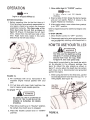
3. Move choke lever to "CHOKE" position.
NOTE
Engine is shipped without oil.
BEFORE STARTING
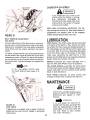
1. Before operating tiller for the first time or if
tines have been removed and reassembled for
any reason, check to be certain the tines are
assembled correctly. The sharp edge of the
tines must enter the soil first as shown in
figure 15. (Figure 15 illustrates the left hand
tines, viewed from the left hand side of the
tiller. Right hand tines rotate in the same
direction as the left hand tines.)
When operating the tiller for the
first time, use the depth bar setting
that gives 1112 inches of tilling depth
(second hole from the top). Refer
to figure 16. Use slow speed only.
Tilling depth is controlled by the depth bar which
can be adjusted to five different settings. See
figure 16. Adjust the side shields as shown in
figure 17, as you adjust the depth bar. Be certain
spark plug wire is disconnected and grounded
against the engine.
1. When using the tiller for the first time, use the
second adjustment hole from the top (1112 II of
tilling depth). See figure 16.
FIGURE 15.
2. Fill crankcase with oil as instructed in the
separate engine manual packed with your
unit.
3. Fill fuel tank with clean, fresh, lead-free, low-
lead or regular grade leaded gasoline.
TO START ENGINE
1. Place drive clutch lever in "Neutral" position.
Be certain tine clutch lever is released.2.
Place the throttle control lever in "START"
position.
FIGURE 16.
9
A warm engine may not require
choking.
4. Stand at side of tiller. Grasp the starter handle
and pullout rapidly. Return it slowly to the
engine. Repeat as necessary.
5. After engine starts, move choke lever gradual-
ly to "OFF" position.
Refer to engine manual for additional engine infor-mation.
TO STOP ENGINE
1. Move throttle control to "OFF" position.
2. Disconnect spark plug wire and ground to pre-
vent accidentally starting while equipment is
unattended.
BE SURE NO ONE IS STANDING IN
FRONT OF THE TILLER WHILE THE
ENGINE IS RUNNING OR BEINGSTARTED.

Do not push down on the handles so
that the wheels are lifted off the
ground while the tine clutch is en-
gaged, or the tiller could move back-
ward and cause personal injury.
For best results, it is recommended the garden be
tilled twice (lengthwise, then widthwise) to
pulverize the soil.
ADJUSTMENTS
FIGURE 17.
2. When breaking up sod and for shallow cultiva-
tion, use the setting which gives 1V2" of till-
ing depth (second hole from the top). Place
the side shields in their lowest position. For
further depth, raise the depth bar and side
shields and make one or two more passes
over the area.
3. When tilling loose soil, depth bar may be
raised to its highest position (use bottom ad-
justment hole) to give the deepest tilling
depth. Raise the side shields to their highest
position.
4. To transport tiller, lower the depth bar (use top
adjustment hole).
To adjust the depth bar, remove the clevis pin and
hairpin cotter. See figure 16. Move the depth bar to
the desired setting.
To adjust the side shields, remove the hex nut and
belleville washer from the front and loosen the
rear nut. See figure 17. Pivot the side shield to the
desired position. Replace hex nut and belleville
washer. Tighten securely.
To operate the tiller:
1. Select the depth bar setting.
2. Start engine as instructed on page 9.
3. Place drive clutch lever in either forward or
reverse position.
4. Engage tine clutch lever.
FIGURE 18.
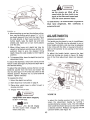
To adjust the handle position from side to side,
loosen the adjustment handle by turning it
counterclockwise several turns. Pull the adjust-
ment handle backward and pivot the tiller handle
to desired position. Release and tighten the ad-
justment handle. See figure 19.
NOTE
To transport tiller, do not engage
the tine clutch lever. Engage the
wheel drive only.
10
HANDLE ADJUSTMENT
The handle may be placed in one of nine different
positions. The handle may be adjusted to one of
three height positions, and also may be adjusted
to be in line with the tiller, or swung to the left or
right so the operator is not walking in the freshly
tilled soil.
To adjust the handle height, remove the hand
knob and locking pin shown in figure 18. Select
one of the three adjustment holes and reassem.
ble.
Engage wheel drive before engaging
the tine clutch lever.

CARBURETOR ADJUSTMENT
Never make unnecessary adjustments. The fac-
tory settings are correct for most applications. If
adjustments are needed, refer to the separate
engine manual packed with your tiller.
FIGURE
19.
LUBRICATION
BELT TENSION ADJUSTMENTTine
Clutch
Periodic adjustment of the belt tension may be re-
quired due to normal stretch and wear on the belt.
Adjustment is needed if the tines seem to hesitate
while tilling, but the engine maintains the samespeed.
To adjust, loosen the hex nuts at the cable bracket
on the handle. See figure 20. With the clutch lever
released as shown in figure 14, adjust the bottom
nut so that there is only a slight amount of slack in
the control wire. Tighten the upper nut against the
bracket.
Chain Cases-The chain cases are pre-lubricatedand
sealed at the factory. They require no check-
ing unless the chain cases are dissassembled. To
fill with grease, lay the left half of the chain case
on its side. Add 12 ounces of plastilube #0 grease
to the tine chain case or 10 ounces to the wheel
chain case. Assemble the right half to it. This
grease can be obtained at your nearest authorizeddealer.
Order part number 737-0133.
Wheels-Lubricate the wheel bearings with a
light oil after each fifteen hours of operation.
NOTE
Do not overtighten control wire.Too
much tension may cause it tobreak.
Tine
Clutch Control-Lubricate the pivot points
on the clutch levers and the cables at least once a
season with light oil. The controls must operate
freely in both directions.
Pivot Points-Lubricate all pivot points and
linkages at least once a season with light oil.
MAl NTENANCE
IMPORTANT
If for any reason the tines are re-
moved from the tiller, be certain the
tines are reassembled so that the
sharp edge of the tines enter the
soil first. Refer to item number
one under "Operation."
FIGURE 20.
Drive Clutch
If adjustment is needed, refer to steps 7 and 8 of
Attaching the Drive Control Cables in Assembly
Instructions.
11
If any adjustments are made to theengine
while the engine is running,(e.g.
carburetor), disengage all
clutches and tines. Keep clear of all
moving parts. Be careful of heated
surfaces and muffler.
Disconnect the spark plug wire and
ground it against the engine before
performing any repairs or main-tenance.

If belt replacement is required, order belt or belts
by part number from your nearest authorized
dealer.
Part No. 754-0195 Tine Belt (1/2" X 54" Long)
Part No. 754-0190 Reverse Drive Belt (V2" x 39"
Long)
Part No. 765-0109 Forward Drive Belt (V2" x 43"
Long)
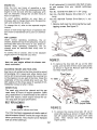
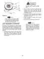
1. Remove belt cover by removing the four self-
tapping screws. See figure 21.
ENGINE OIL
After the first two hours of operating a newengine,
drain the oil from the crankcase while the
engine is still hot and refill the crankcase with
new oil; thereafter change the oil after every 25
hours of operation.
To avoid spilling gasoline on your lawn or
driveway, plan to change the oil when the gasoline
tank and carburetor are empty.
To change the oil, refer to the separate engine
manual.
Check oil level every eight hours of operation. Be
sure level is maintained full to point of overflow-
ing.
AIR CLEANER
Under normal operating conditions, the air
cleaner, located on top of the carburetor, must be
serviced after every ten hours of use. Under ex-
tremely dusty operating conditions, the air
cleaner must be serviced after every hour of
operation.
To service the air cleaner, refer to the separate
engine manual packed with your tiller.
FIGURE 21.
IMPORTANT
Never run your engine without air cleaner com.pletelyassembled.
2.
To remove the tine belt, lift up on the idler
pulley, and slip belt off tine chain case pulley
as shown in figure 22. Remove belt from the
two-step engine pulley.
CLEANING ENGINE AND TINE AREA
Any fuel or oil spilled on the tiller should be wiped
off promptly. Dirt, leaves and other debris must
not be left to accumulate around the cooling fins
or the engine or on any part of the tiller. Clean the
underside of the tine shield after each use. The
dirt washes off the tines easier if washed off im-
mediately instead of after it dries.
Tine Chain
I
-I
Be~
~ / Idler~
Pull e y
~
~~
~
~-
SPARK PLUG
The spark plug should be cleaned and the gap
reset every 25 hours of engine operation. Spark
plug replacement is recommended at the start of
each tiller season; check engine manual for cor-
rect plug type and gap specification.
q,
\
~
'
~.- ~
.Two.Step
;. ((;)\ Engine Pulley
BELT REPLACEMENT
FIGURE 22.
NOTE
Do not use an off-the-shelf belt.
3.
To remove the reverse drive belt, lift up on
small idler pulley as shown in figure 23. Slip
belt off outside sheave of wheel chain case
pulley. Then remove belt from two-step
engine pulley.
Your tiller has been engineered with belts made of
special material (KevlarTensile) for longer life and
better performance. They should not be replaced
with an off-the-shelf belt.
12

Wheel Chain
Case Pulley
/ 1-1
Small I
Pulle
L
)
J
~
Wheel Chain
Case Pulley Forward
.~ve Belt
rSOl~1
tr'
If,
J/-
'",.
~ "
~ ~'
'~ -~
: -;')
'"
6)
{2)\~~
~
~L
< ...~
~~,"'~
'- --'.'- \~
Reverse Drive I)
~J;
--~
-'"
--:::c:;:
Two-Step
Engine Pulley
-\-
Forward
Engine Pulley
~
" I
FIGURE 25.
FIGURE 23.
Reassemble new belts, following instructionsin
reverse order.
IMPORTANTWhen
reassembling belts, be certain
belts are routed around all belt
keeper pins as shown in figure 26.
4.
To remove the forward drive belt, proceed as
follows.
A. Loosen (do not remove) the hex nut at the
top of the wire belt keeper.
B. Pull bottom of wire belt keeper out and
then upward, pivoting it away from the for-
ward engine pulley. See figure 24.
FIGURE 24.
NOTE
Upon reassembly, refer to illustra-
tion on page 18 for correct assembly
of wire belt guard for your modeltiller.
C.
Lift belt off the forward engine pulley. See
figure 25.D.
Remove belt from inside sheave of wheel
chain case pulley.
13

FIGURE 27.
NOTE
If the "V"-idler or flat idler pulleys
are removed for any reason, be sure
to install with hub side against the
idler bracket. See figure 27.
2.
Drain all the oil from the crankcase (this
should be done after the engine has been
operated and is still warm) and refill the
crankcase with clean new oil as instructed in
the engine manual.
3. Protect the inside of the engine for storage as
instructed in the separate engine manual
packed with your unit.
4. Clean the exterior of engine and the entire
tiller thoroughly.
5. Wipe tines with oiled rag to prevent rust.
When storing any type of power
equipment in an unventilated or
metal storage shed, care should be
taken to rustproof the equipment.
Using a light oil or silicone, coat the
equipment, especially any springs,
bearings and cables.
If the tiller is to be inoperative for a period longer
than 30 days, the following precautions are recom-
mended. Keep your tiller in a weatherproof, dry
area. If stored for over 30 days the following steps
will protect the essential engine parts from gum
deposits.
1. Working outdoors, drain all fuel from the fuel
tank. Use a clean, dry cloth to absorb the
small amount of fuel remaining in the tank,
then run the engine until all fuel in carburetor
is exhausted.
14
DO NOT DRAIN FUEL WHILESMOKING,
OR IF NEAR AN OPENFIRE.

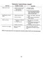
SYMPTOM
POSSIBLE CAUSE(S)
SOLUTION
Engine fails to start
1. Check fuel tank for gas.2.
Spark plug lead wire
disconnected.3.
Faulty spark plug.
1. Fill tank if empty.
2. Connect lead wire.
3.
Spark should jump gap between
control electrode and side elec-
trode. If spark does not jump,
replace the spark plug.
Hard starting or loss of
power
1. Spark plug wire loose.
2. Dirty air cleaner.
1. Connect and tighten spark plug
wire.2.
Clean air cleaner as described in
engine manual.
Engine
overheats
1. Carburetor not adjusted
.properly.
2. Air flow restricted.
~Engine
oil revel low.
1. Adjust carburetor. See engine
manual.2.
Remove blower housing and clean
as described in the engine
manual.3.
Fill crank~V!ith the proper oil.
Controls do not engage
Belts worn and/orstretched.
Make control cable adjustment
(see adjustment section) or replace
belts.
NOTE: For repairs beyond the minor adjustments listed above, please contact your local service dealer.
15

A
A
2
\ -,
(\=:J~~3 /
\ \ --71 ~,
'6 ~
I
,68
78-
,
94
/
69
/
/'
/'
'"
/
/,
'"
'"
73-
Q
---
\
72'1!!!1J
64.
23,
17"
77
75
86
/
'.- \ "
1 2 ' Ii'.
\I .
62 \!
\ (- KJ
-\1 I /
')Ii
61
\
~
I
I,
18
/ J.9
"'11/
;.- 60-;1'
\
\,
--20
21
~2
~
18\ sh
-2'25
/
/
22
-'~ r
J ~ ~
-4')
)--
e
26/
27
./%
3'7
/~./
~o
/-
/59
/
e&j:
36"
/
I
t
~
.?~
~
~
0
28
/
-:;'/ (,
.38 ~-"
~\
I
"
/
\'~ i
I,
/)
./r~
~
~ I
~8
34~31
"
.17
\
I47
36
"
~
~
5i~" :/1f
", -'
,,'
~'" " y51
---52
""'53
,:~
/
45
/~
34 33 (
./
35
~\
16
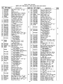
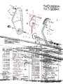
Wire Assembled in Upper Hole
on Model TMO-39083A
Wire Assembled in Lower Hole
on Model TMO.39084A
,

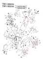
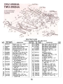
REAR TINE TILLERS
PARTS LIST FOR MODELS TMO.39083A AND TMO.39084A
---
REF.
NO.
1
2
3
4
5
7
9
10
PART COLOR
NO. CODE
710-0299
720-0180
747-0517
712-0117
710-0458
784-0031
15093
710-0607
NEWI~
REF.
NO.
46
47
48
49
50
51
52
53
54
55
56
57
58
59
PART COLOR
NO. CODE
712-0267
736-0119
712-0267
736-0119
14975 -615
726-0175
736-0119
712-0267
710-0118
720-0165
736-0169
712-0798
710-0118
15393
NEW I~
DESCRIPTION
DESCRIPTION
N
11 712-0256
12 736-011913
746-0535
14
15
16
17
18
19
20
21
22
23
24
712-0267
736-0119
784-0133
749-0643
712-0798
736-0169
736-0105
710-0253
714-0507
725-0157
747-0432
N
784-0087
N
60
1 710-0118
61 784-0026
784-0085
N
62
63
64
65
66
67
68
69
714-0149
711-0415
749-0642
720-0195
714-0127
712-0375
720-0143
738-0575
747-0501
25
14989
14990
26 736-0242
27 712-0267
28 15390 -615
29 15397
70
71
72
741-0402738-0561
746-0502
15398
746-0512
784-0083
73 831-0692
74 736-0219
75 784-0022
76 738-0281
784-0082
3031
32
33
34
712-0241
736-0169710-0191
714-0149
14978
77
78
79
80
81
82
83
84
85
784-0019
784-0025
712-0375
736-0105
736-0253
711-0765
784-0023
736-0463
732-0145
784-0084
35
36
37
38
39
40
742-0106
742-0105
711-0415
712-0267
736-0119
14979
86
738-0147
87
710-0599
784-0088
88
89
90
91
92
93
94
736-0242
712-0158
736-0159
735-0126
746-0572
746-0571
736-0285
Hex Nut 5/16-18 Thd.*
L-Wash. 5/16" 1.0.*
Hex Nut 5/16-18 Thd.*
L-Wash. 5/16" 1.0.*
Frame Rail-L.H.
Clamp 5/16" Dia.
L-Wash. 5/16" 1.0.*
Hex Nut 5/16-18 Thd.*
Hex Bolt 5/16-18 x 3/4" Lg.*
Ball Knob 11/4" Dia.
L-Wash. 3/8" 1.0.*
Hex Nut 3/8-16 Thd.*
Hex Bolt 5/16-18 x .75" Lg.*
Brkt. Reinforcement
(TMO-39084A)
Brkt. Rei nforcement
(TM 0-39083A)
Hex Bolt 5/16-18 x .75" Lg.*
Tine Shield Ass'y.
(TM 0-39084A)
Tine Shield Ass'y.
(TM 0-39083A)
Hairpin Cotter
Clevis Pin 3/8" Dia.
Handle-R.H.
Hand Knob
Cotter Pin 1/16" Dia. x .75"*
Hex Cent. L-Nut 3/8-16 Thd.
Grip
Shoulder Bolt .375" Dia. x
1.37" Lg.
Hex Flange Plastic Bearing
Shoulder Nut V4-20 Thd.
Throttle Control Wire
(TM 0-39084A)
Throttle Control Wire
(TM 0-39083A)
Throttle Control Box Ass'y.
Bell-Wash. .40" 1.0. x 1.13"
Handle Pivot Bracket
Shoulder Bolt 5/8" Dia. x
.165" Lg.
Handle Mtg. Bracket
Adj. Handle Ass'y.
Hex Cent. L-Nut 3/8-16 Thd.
Bell-Wash. .40" 1.0. x .88"
Bell-Wash. V2" 1.0. x 1.00"
Lock Pin 5/16" Dia. x 8"
Lower Sliding Ass'y.
FI-Wash. .291" 1.0. x .62"
Compression Spring .36"
0.0. x 1.00" Lg.
Shoulder Bolt V2" Dia. x
.170" Lg.
Hex Wash. S- Tap Scr. 1/4-20
x .50" Lg.
Bell-Wash. 5/16" 1.0.
Hex Cent. L-Nut 5/16-18 Thd.
FI-Wash. .344" 1.0. x .87"
Rubber Wash. .33 1.0. x .87"
Control Cable (Forward)
Control Cable (Reverse)
FI-Wash. .62" 1.0. x 1.57"
N
41
42
43
44
45
710-0736
738-0507
736-0117
710-0216
14992
Hex Bolt 1/4-28 x 1.0" Lg.*
Grip
Clutch Lever
Hex Cent. L-Nut 1/4-28 Thd.
Carr. Bolt 5/16-18 x 1.75"*
Clutch Grip Ass'y.-L.H.
Clutch Cable Bracket
Hex Wash. S-Tap Scr.
5/16-18 x .62" Lg.
Hex Nut 5/16-24 Thd.
L-Wash. 5/16" 1.0.*
Clutch Control Cable
(Tines)
Hex Nut 5/16-18 Thd.*
L-Wash. 5/16" 1.0.*
Handle Panel Ass'y.
Handle-L.H.
Hex Nut 3/8-16 Thd.*
L-Wash. 3/8" 1.0.*
Bell-Wash. 3/8" 1.0.
Hex Bolt 3/8-16 x 1.00" Lg.*
Cotter Pin 3/32" Dia. x 3/4"*
Cable Tie
Tiller Flap Aod
(TM 0-39084A)
Tiller Flap Aod
(TMO-39083A)
End Cover Ass'y.-L.H.
End Cover Ass'y.-A.H.
(Not Shown)
Bell-Wash. 5/16" 1.0.
Hex Nut 5/16-18 Thd.*
Side Shield
L.H. Tine Ass'y. Compo
(T M 0-39084A)
A.H. Tine Ass'y. Camp.
(TMO-39084A) (Not Shown)
L.H. Tine Ass'y. Compo
(TMO-39083A)
A.H. Tine Ass'y. Camp.
(TMO-39083A) (Not Shown)
Hex Nut 3/8-24 Thd.*
L-Wash. 3/8" 1.0.*
Hex Bolt 3/8-24 x 1.25" Lg.*
Hairpin Cotter
Tine Adapter Ass'y.
(TM 0-39084A)
Tine Adapter Ass'y.
(TMO-39083A)
Tine 12" A.H.
I Tine 12" L.H.
Clevis Pin 3/8" Dia.
Hex Nut 5/16-18 Thd.*
L-Wash. 5/16" 1.0.*
Tine Shield Flap
(TM 0-39084A)
Tine Shield Flap
(TM 0-39083A)
Hex Bolt 5/16-18 x 1.0" Lg.*
Shld. Bolt V2" Dia. x .426"
FI-Wash. 3/8" 1.0. x 5/8" 0.0.
Hex Bolt 3/8-16 x 3/4" Lg.*
~th Bar As~.
17

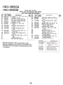
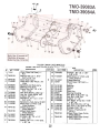
REAR TINE TILLERS
PARTS LIST FOR MODELS TMO.39083A AND TMO.39084A
I REF.
NO.
NEW I REF.!~~
PARTlcOLOR~
CODE
INEW
PART
DESCRIPTION
DESCRIPTION
1
PART COLOR
NO. CODE750-0219
22 712-026623
710-0118
24 747-0507
747-0506
712-0287
736-0270
2
3
4
5
746-053515093710-0118
732-0387
25
26
6
712-0266
7 712-0107
8 732-0445
27
784-013128
1 738-0147
29 784-0127
9 15093
10 710-0118
11 746-0571
30
736-0326
31
32
714-0131
756-0386
12
1746-0572
33
34
35
36
37
38
39
754-0109
756-0166
712-0116
756-0465
754-0190
712-0116
736-0231
13 712-0266
14 712-0107
15 -
16 1712-0107
17 732-0486
18 710-0442
19 -
20 714-0105
21 732-0433
4041
42
736-0119
710-0117
754-0195
Hex Cent. L-Nut 3/8-16 Thd.
Hex Bolt 5/16-18 x .75" Lg.*
Belt Keeper (TMO-39084A)
I Belt Keeper (TMO-39083A)
Hex Nut V4-20 Thd.*
Bell-Wash. .265" 1.0. x .75"
0.0.
Idler Brkt. Ass'y.
(Wheel Reverse)
Shld. Bolt .500" Dia. x .170
Idler Brkt. Ass'y.
(Wheel Forward)
FI-Wash. .510" 1.0. x 1.0"
0.0.
#5 Hi-Pro-Key 1/8" x 5/8" Dia.
V2" V-Pulley 2.25" 0.0. x
.503" 1.0.
"V"-Belt V2" x 43.0" Lg.
"V"-Belt Idler 2.62" 0.0.
Hex Ins. L-Nut 3/8-24 Thd.
V2" "V"-Pulley Ass'y.
"V"-Belt V2" x 39.0" Lg.
Hex Ins. L-Nut 3/8-24 Thd.
FI-Wash. .344" 1.0. x 1.125"
0.0.
L-Wash. 5/16" 1.0.*
Hex Bolt 5/16-24 x 1.00" Lg.*
"V"-Belt V2" x 54.0" Lg.
Spacer
.375" 1.0. x .500"
0.0. x 2.00" Lg.
Clutch Control Cable (Tines)
Clutch Cable Bracket
Hex Bolt 5/16-18 x .75" Lg.*
Extension Spring .50" 0.0.
x 2.50" Lg.
Hex Cent. L-Nut 3/8-16 Thd.
Hex Cent. L-Nut 1/4" Thd.
Extension Spring .50" 0.0.
x 1.55" Lg.
Clutch Cable Bracket
Hex Bolt 5/16-18 x .75" Lg.*
Clutch Control Cable 42"
Lg. (Forward)
Clutch Control Cable 41"
Lg. (Reverse)
Hex Cent. L-Nut 3/8-16 Thd.
Hex Cent. L-Nut 1/4-20 Thd.
Springs (Part of Ref. No. 11
and 12)
Hex Cent. L-Nut 1/4-20 Thd.
Extension Spring .41" 0.0.
x 2.05" Lg.
Hex Bolt 5/16-18 x 1.50" Lg.*
Engine
Sq. Key 3/16 x 1.00" Lg.
Extension Spring .50" 0.0.
x 2.75" Lg.
18

59
714-0388
60
61
62
63
64
750-0551
712-0267
736-0119
712-0267
736-0185
50
756-0389
51
756-0405
65
66
67
68
52
756-0464
53
756-0313
54 I
69
710-0237
Idler Brkt. Ass'y.- Tines
Shld. Bolt. .500" Dia. x .215"
Lg.
#61 Hi-Pro-Key 3/16" x 5/8"
Dia.
Spacer .647" I.D. x 2.75" Lg.I
Hex Nut 5/16-18 Thd.*
I-Wash. 5/16" I.D.*
Hex Nut 5/16-18 Thd.*
I:-I-Wash. .406" I.D. x .750"
O.D.
Side Plate Ass'y.
Set Scr. 1/4-28 x .25" Lg.
L-Wash. 5/16" I.D.*
Hex Bolt 1/4-20 x 1.25" Lg.*
(TMO-39083A)
Hex Bolt 5/16-24 x .62" Lg.
(TM 0-39083A)
Bell-Wash. 5/16" I.D.
55
156
FI-Wash. 1/4" 1.0. X .93" 0.0.
L-Wash. 1/4" 1.0.*
Hex Bolt 1/4-28 x .75" Lg.
Hex Ins. L-Nut 3/8-24 Thd.
Hex Bolt 1/4-28 x .75" Lg.
L-Wash. 1/4" 1.0.*
FI-Wash. 1/4" 1.0. x .93"
0.0.
FI-Pulley w/Flanges 6.0"
0.0.
FI-ldler w/Flanges 3.75"
0.0.
Double FI-Pulley 5/8" 1.0. x
6.0" 0.0.
FI-ldler with Flanges 2.12"
0.0.Shld.
Bolt .500" Dia. x .170"
Lg.
L-Wash. 5/16" 1.0.*
Hex Nut 5/16-18 Thd.*
70
736-0242
.Common Hardware-May be purchased locally.
Important: Do not order by reference number (Ref. No.).
Note: Specifications subject to change without notice
or obligation.
19
TMO-39084A REAR TINE TILLERS
PARTS LIST FOR MODELS TMO.39083A
AN D TMO.
REF. PART COLOR DESCRIPTION OR DESCRIPTION NEW
NO. NO. CODE DE PART
43 736-0176 57 784.0129
44 736-0329 58 738-0183
45 710-0412
46 712-0116
47 710-0412
48 736-0329
49 736-0176

)8
.,
,.2
3-?
~
'~ .\ I.
\\ , -;
~
~~ '"
'",
, ~
~~,~
,/,-
Lv
.'- ",>J ~
!Jf"'"
~'--
'<.:-
36
~
f{.,
26:-
~..Jt~~ ~~~[ ,"'/($
.\ 2' ~v
1 ~
I 23 '9
2' '8
/25
\ ( ~ ~~ \
,
Jt\
\ \29
28
~
27
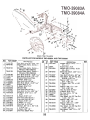
REAR TINE TILLERS
PARTS LIST FOR MODELS TMO.39083A AND TMO.39084A
DESCRIPTION DESCRIPTION
1
1710-0189
2 784-0106
25
1734-1255
26 114974
27 734-1254
3
784-0104
784-0105
28 1736-0242
4
5
6
7
8
91011
12
13
14
15
710-0189
710-0118
14973
736-0119
~ 712-0267
710-0830
14975
736-0119
723-0340
712-0267
710-0786
736-0326
29
1710-0237
30 710-0600
31
750-0470
32 1736-0256
33 1750-0470
34
35
36
37
38
712-0267736-0119714-0122
14980
710-0599
16
17
18
19
2021
22
736-0119
712-0267
712-0267
736-0119
736-0921
712-0206
750-0579
39 1750-0470
40 1750-0219
10-0599
Wheel Ass'y. Compo 12.5 x
3.5-L.H.
Frame Rail-R.H.
Wheel Ass'y Compo 12.5 x
3.5-R.H.
Belleville Wash. .345" 1.0. x
.88" 0.0.
Hex Bolt 5/16-24 x .62" Lg.*
Hex Wash. Hd. SF-Tap Scr.
5/16-24 x .50" Lg.
Spacer .326" 1.0. x .47"
0.0. x .96" Lg.
FI-Wash. .635" 1.0. x 1.00"
0.0.
Spacer .326" 1.0. x .47"
0.0. x .96" Lg.
Hex Nut 5/16-18 Thd.*
L-Wash. 5/16" 1.0.*
Sq. Key 3/16 x .75" Lg.
Belt Cover
Hex Wash. Hd. SF-Tap Scr.
1/4-20 x .50" Lg.
Spacer .326" 1.0. x .47"
0.0. x .96" Lg.
Spacer .375" 1.0. x .500"
0.0. x 2.00" Lg.
Hex Wash. Hd. SF-Tap Scr.
1/4 -20 x .50" Lg.
Bell-Wash. .265" 1.0. x .75"
0.0.
41
23
1 736-0169
24 712-0241
Hex Bolt 5/16-18 x 3.00" Lg.*
Chain Case Ass'y. Comp.-
Tines
Chain Case Ass'y. Comp.-
Wheels (TMO-39084A)
Chain Case Ass'y. Comp.-
Wheels (TMO-39083A)
Hex Bolt 5/16-18 x 3.00" Lg.*
Hex Bolt 5/16-18 x .75" Lg.*
Engine Mounting Plate
I -Wash. 5/16" I.D.*
Hex Nut 5/16-18 Thd.*
Hex Bolt 3/8-24 x 3.00" Lg.*
r-rame Rail-L.H.
I -Wash. 5/16" I.D.*
Weight 35#
Hex Nut 5/16-18 Thd.*
Hex Bolt V2-13 x 4.00" Lg.*
I=I-Wash. .510" I.D. x 1.0"
O.D.
.Wash. 5/16" I.D.*
Hex Nut 5/16-18 Thd.*
Hex Nut 5/16-18 Thd.*
,1--Wash. 5/16" I.D.*
L-Wash. V2" I.D.*
Hex Nut V2-13 Thd.*
~pacer .38" I.D. x .62" O.D.
x 2.18" Lg.
-Wash. 3/8" I.D.*
Hex Nut 3/8-24 Thd.*
42 1736-0270
20
i
9
/
'. ,
'. ". , 10
~"'2:--~., /. 12
~~. II
I
..
~I"" I I
'\ 16 15 ,~
17
Page is loading ...
Page is loading ...
Page is loading ...
Page is loading ...
-
 1
1
-
 2
2
-
 3
3
-
 4
4
-
 5
5
-
 6
6
-
 7
7
-
 8
8
-
 9
9
-
 10
10
-
 11
11
-
 12
12
-
 13
13
-
 14
14
-
 15
15
-
 16
16
-
 17
17
-
 18
18
-
 19
19
-
 20
20
-
 21
21
-
 22
22
-
 23
23
-
 24
24


Montgomery Ward TMO-39083A User manual
- Category
- Mini tillers
- Type
- User manual
- This manual is also suitable for
Ask a question and I''ll find the answer in the document
Finding information in a document is now easier with AI
Other documents
-
Bolens Grt5 User manual
-
Electrolux 213-430-000 User manual
-
MTD 219-381-000 User manual
-
-
-
-
White Outdoor ROTO BOSS 510 217-310-190 User manual
-
-
White 210-310-190 User manual
-