Page is loading ...

INSTALLATION/OPERATION
C2927M-D (9/09)
PMCL400 Series
TFT LCD Monitor


C2927M-D (9/09) 3
Contents
Important Safety Instructions . . . . . . . . . . . . . . . . . . . . . . . . . . . . . . . . . . . . . . . . . . . . . . . . . . . . . . . . . . . . . . . . . . . . . . . . . . . . . . . . . . . . . . . . . . . . 6
Important Notices . . . . . . . . . . . . . . . . . . . . . . . . . . . . . . . . . . . . . . . . . . . . . . . . . . . . . . . . . . . . . . . . . . . . . . . . . . . . . . . . . . . . . . . . . . . . . . . . . . . . . 7
Legal Notice . . . . . . . . . . . . . . . . . . . . . . . . . . . . . . . . . . . . . . . . . . . . . . . . . . . . . . . . . . . . . . . . . . . . . . . . . . . . . . . . . . . . . . . . . . . . . . . . . . . . . 7
Regulatory Notices . . . . . . . . . . . . . . . . . . . . . . . . . . . . . . . . . . . . . . . . . . . . . . . . . . . . . . . . . . . . . . . . . . . . . . . . . . . . . . . . . . . . . . . . . . . . . . . . 7
Description. . . . . . . . . . . . . . . . . . . . . . . . . . . . . . . . . . . . . . . . . . . . . . . . . . . . . . . . . . . . . . . . . . . . . . . . . . . . . . . . . . . . . . . . . . . . . . . . . . . . . . . . . . . 8
Models . . . . . . . . . . . . . . . . . . . . . . . . . . . . . . . . . . . . . . . . . . . . . . . . . . . . . . . . . . . . . . . . . . . . . . . . . . . . . . . . . . . . . . . . . . . . . . . . . . . . . . . . . 8
Recommended Mounts. . . . . . . . . . . . . . . . . . . . . . . . . . . . . . . . . . . . . . . . . . . . . . . . . . . . . . . . . . . . . . . . . . . . . . . . . . . . . . . . . . . . . . . . . . . . . 8
Package Contents . . . . . . . . . . . . . . . . . . . . . . . . . . . . . . . . . . . . . . . . . . . . . . . . . . . . . . . . . . . . . . . . . . . . . . . . . . . . . . . . . . . . . . . . . . . . . . . . . 9
Installation . . . . . . . . . . . . . . . . . . . . . . . . . . . . . . . . . . . . . . . . . . . . . . . . . . . . . . . . . . . . . . . . . . . . . . . . . . . . . . . . . . . . . . . . . . . . . . . . . . . . . . . . . . 10
Desk Stand . . . . . . . . . . . . . . . . . . . . . . . . . . . . . . . . . . . . . . . . . . . . . . . . . . . . . . . . . . . . . . . . . . . . . . . . . . . . . . . . . . . . . . . . . . . . . . . . . . . . . 10
Wall Mounting . . . . . . . . . . . . . . . . . . . . . . . . . . . . . . . . . . . . . . . . . . . . . . . . . . . . . . . . . . . . . . . . . . . . . . . . . . . . . . . . . . . . . . . . . . . . . . . . . . 10
Rack Mounting . . . . . . . . . . . . . . . . . . . . . . . . . . . . . . . . . . . . . . . . . . . . . . . . . . . . . . . . . . . . . . . . . . . . . . . . . . . . . . . . . . . . . . . . . . . . . . . . . . 11
Rear Panel Connectors . . . . . . . . . . . . . . . . . . . . . . . . . . . . . . . . . . . . . . . . . . . . . . . . . . . . . . . . . . . . . . . . . . . . . . . . . . . . . . . . . . . . . . . . . . . . 12
Operation . . . . . . . . . . . . . . . . . . . . . . . . . . . . . . . . . . . . . . . . . . . . . . . . . . . . . . . . . . . . . . . . . . . . . . . . . . . . . . . . . . . . . . . . . . . . . . . . . . . . . . . . . . . 13
Front Panel Controls . . . . . . . . . . . . . . . . . . . . . . . . . . . . . . . . . . . . . . . . . . . . . . . . . . . . . . . . . . . . . . . . . . . . . . . . . . . . . . . . . . . . . . . . . . . . . . 13
Remote Control Functions. . . . . . . . . . . . . . . . . . . . . . . . . . . . . . . . . . . . . . . . . . . . . . . . . . . . . . . . . . . . . . . . . . . . . . . . . . . . . . . . . . . . . . . . . . 14
On-Screen Display Function . . . . . . . . . . . . . . . . . . . . . . . . . . . . . . . . . . . . . . . . . . . . . . . . . . . . . . . . . . . . . . . . . . . . . . . . . . . . . . . . . . . . . . . . 15
Video 1, Video 2, S-Video Mode Menu . . . . . . . . . . . . . . . . . . . . . . . . . . . . . . . . . . . . . . . . . . . . . . . . . . . . . . . . . . . . . . . . . . . . . . . . . . . 16
RGB and DVI Mode Menu . . . . . . . . . . . . . . . . . . . . . . . . . . . . . . . . . . . . . . . . . . . . . . . . . . . . . . . . . . . . . . . . . . . . . . . . . . . . . . . . . . . . . 18
Troubleshooting . . . . . . . . . . . . . . . . . . . . . . . . . . . . . . . . . . . . . . . . . . . . . . . . . . . . . . . . . . . . . . . . . . . . . . . . . . . . . . . . . . . . . . . . . . . . . . . . . . . . . . 20
Maintenance . . . . . . . . . . . . . . . . . . . . . . . . . . . . . . . . . . . . . . . . . . . . . . . . . . . . . . . . . . . . . . . . . . . . . . . . . . . . . . . . . . . . . . . . . . . . . . . . . . . . . . . . 20
Specifications . . . . . . . . . . . . . . . . . . . . . . . . . . . . . . . . . . . . . . . . . . . . . . . . . . . . . . . . . . . . . . . . . . . . . . . . . . . . . . . . . . . . . . . . . . . . . . . . . . . . . . . 21
Appendix . . . . . . . . . . . . . . . . . . . . . . . . . . . . . . . . . . . . . . . . . . . . . . . . . . . . . . . . . . . . . . . . . . . . . . . . . . . . . . . . . . . . . . . . . . . . . . . . . . . . . . . . . . . 22
RGB/DVI Mode Supported Frequencies . . . . . . . . . . . . . . . . . . . . . . . . . . . . . . . . . . . . . . . . . . . . . . . . . . . . . . . . . . . . . . . . . . . . . . . . . . . . . . . 22

4 C2927M-D (9/09)
List of Illustrations
1 Package Contents . . . . . . . . . . . . . . . . . . . . . . . . . . . . . . . . . . . . . . . . . . . . . . . . . . . . . . . . . . . . . . . . . . . . . . . . . . . . . . . . . . . . . . . . . . . . . . . . . 9
2 Attaching the Mount in a Wall Installation . . . . . . . . . . . . . . . . . . . . . . . . . . . . . . . . . . . . . . . . . . . . . . . . . . . . . . . . . . . . . . . . . . . . . . . . . . . . 10
3 Installing the Brackets in a Rack Mount Installation . . . . . . . . . . . . . . . . . . . . . . . . . . . . . . . . . . . . . . . . . . . . . . . . . . . . . . . . . . . . . . . . . . . . . 11
4 Installing the Monitor in the Rack . . . . . . . . . . . . . . . . . . . . . . . . . . . . . . . . . . . . . . . . . . . . . . . . . . . . . . . . . . . . . . . . . . . . . . . . . . . . . . . . . . . 11
5 Rear Panel Connectors . . . . . . . . . . . . . . . . . . . . . . . . . . . . . . . . . . . . . . . . . . . . . . . . . . . . . . . . . . . . . . . . . . . . . . . . . . . . . . . . . . . . . . . . . . . . 12
6 Front Panel Controls . . . . . . . . . . . . . . . . . . . . . . . . . . . . . . . . . . . . . . . . . . . . . . . . . . . . . . . . . . . . . . . . . . . . . . . . . . . . . . . . . . . . . . . . . . . . . . 13
7 Remote Control . . . . . . . . . . . . . . . . . . . . . . . . . . . . . . . . . . . . . . . . . . . . . . . . . . . . . . . . . . . . . . . . . . . . . . . . . . . . . . . . . . . . . . . . . . . . . . . . . . 14
8 Input Source Name Display . . . . . . . . . . . . . . . . . . . . . . . . . . . . . . . . . . . . . . . . . . . . . . . . . . . . . . . . . . . . . . . . . . . . . . . . . . . . . . . . . . . . . . . . 15
9 Video 1, Video 2, S-Video Mode Menu . . . . . . . . . . . . . . . . . . . . . . . . . . . . . . . . . . . . . . . . . . . . . . . . . . . . . . . . . . . . . . . . . . . . . . . . . . . . . . . 16
10 RGB and DVI Mode Menu. . . . . . . . . . . . . . . . . . . . . . . . . . . . . . . . . . . . . . . . . . . . . . . . . . . . . . . . . . . . . . . . . . . . . . . . . . . . . . . . . . . . . . . . . . 18

C2927M-D (9/09) 5
List of Tables
A Troubleshooting the PMCL400 Series Monitor . . . . . . . . . . . . . . . . . . . . . . . . . . . . . . . . . . . . . . . . . . . . . . . . . . . . . . . . . . . . . . . . . . . . . . . . . 20
B RGB and DVI Mode Supported Frequencies. . . . . . . . . . . . . . . . . . . . . . . . . . . . . . . . . . . . . . . . . . . . . . . . . . . . . . . . . . . . . . . . . . . . . . . . . . . . 22

6 C2927M-D (9/09)
Important Safety Instructions
1. Read these instructions.
2. Keep these instructions.
3. Heed all warnings.
4. Follow all instructions.
5. Do not use this apparatus near water.
6. Clean only with dry cloth.
7. Do not block any ventilation openings. Install in accordance with the manufacturer’s instructions.
8. Do not install near any heat sources such as radiators, heat registers, stoves, or other apparatus (including amplifiers) that produce heat.
9. Do not defeat the safety purpose of the polarized or grounding-type plug. A polarized plug has two blades with one blade wider than the
other. A grounding plug has two blades and a third grounding prong. The wide blade or the third prong are provided for your safety. If the
provided plug does not fit into your outlet, consult an electrician for replacement of the obsolete outlet.
10. Protect the power cord from being walked on or pinched particularly at plugs, convenience receptacles, and the points where they exit from
the apparatus.
11. Only use attachments/accessories specified by the manufacturer.
12. Only use with the cart, stand, tripod, bracket, or table specified by the manufacturer, or sold with the apparatus. When a cart is used, use
caution when moving the cart/apparatus combination to avoid injury from tip-over.
13. Refer all servicing to qualified service personnel. Servicing is required when the apparatus has been damaged in any way, such as power-
supply cord or plug is damaged, liquid has been spilled or objects have fallen into the apparatus, the apparatus has been exposed to rain or
moisture, does not operate normally, or has been dropped.
14. Unplug the apparatus during lightning storms or when unused for long periods of time.
15. Apparatus shall not be exposed to dripping or splashing and no objects filled with liquids, such as vases shall be placed on the apparatus.
16. WARNING: To reduce the risk of fire or electric shock, do not expose this apparatus to rain or moisture.
17. Installation should be done only by qualified personnel and conform to all local codes.
18. Unless this unit is specifically marked as NEMA Type 3, 3R, 3S, 4, 4X, 6, or 6P enclosure, it is designed for indoor use only and it must not
be installed where exposed to rain and moisture.
19. Only use installation methods and materials capable of supporting four times the maximum specified load.
20. Only use replacement parts recommended by Pelco.
21. Avoid touching the screen directly with your fingers as the oils from your skin may be difficult to remove from the LCD.
22. Do not apply direct pressure on the screen.
23. Keep the monitor in a dust-free environment and away from strong electromagnetic fields.
24. Do not use attachments, such as mounts, that are not recommended by Pelco. They may be hazardous.
25. Do not place the monitor on an unstable stand, bracket, or mount. The unit may fall, causing serious damage to the unit or injury to a
person. Only use mounts recommended by Pelco.
26. A CCC-approved power cord must be used to power this equipment when used in China.
27. A still image displayed too long may cause permanent damage to the LCD panel. Watching the LCD in 4:3 format for a long time may leave
traces of borders displayed on the left, right and center of the screen caused by the difference of light emission on the screen. Using a
camera or a system may cause a similar effect to the screen. Damages caused by this effect are not covered by the warranty.
The product and/or manual may bear the following marks:
This symbol indicates that dangerous voltage constituting a risk of electric shock is present
within this unit.
This symbol indicates that there are important operating and maintenance instructions in the
literature accompanying this unit
CAUTION:
RISK OF ELECTRIC SHOCK.
DO NOT OPEN.

C2927M-D (9/09) 7
Important Notices
LEGAL NOTICE
SOME PELCO EQUIPMENT CONTAINS, AND THE SOFTWARE ENABLES, AUDIO/VISUAL AND RECORDING CAPABILITIES, THE IMPROPER USE OF
WHICH MAY SUBJECT YOU TO CIVIL AND CRIMINAL PENALTIES. APPLICABLE LAWS REGARDING THE USE OF SUCH CAPABILITIES VARY
BETWEEN JURISDICTIONS AND MAY REQUIRE, AMONG OTHER THINGS, EXPRESS WRITTEN CONSENT FROM RECORDED SUBJECTS. YOU
ARE SOLELY RESPONSIBLE FOR INSURING STRICT COMPLIANCE WITH SUCH LAWS AND FOR STRICT ADHERENCE TO ANY/ALL RIGHTS OF
PRIVACY AND PERSONALTY. USE OF THIS EQUIPMENT AND/OR SOFTWARE FOR ILLEGAL SURVEILLANCE OR MONITORING SHALL BE DEEMED
UNAUTHORIZED USE IN VIOLATION OF THE END USER SOFTWARE AGREEMENT AND RESULT IN THE IMMEDIATE TERMINATION OF YOUR
LICENSE RIGHTS THEREUNDER.
REGULATORY NOTICES
This device complies with Part 15 of the FCC Rules. Operation is subject to the following two conditions: (1) this device may not cause harmful
interference, and (2) this device must accept any interference received, including interference that may cause undesired operation.
RADIO AND TELEVISION INTERFERENCE
This equipment has been tested and found to comply with the limits of a Class B digital device, pursuant to Part 15 of the FCC Rules. These limits
are designed to provide reasonable protection against harmful interference in a residential installation. This equipment generates, uses, and can
radiate radio frequency energy and, if not installed and used in accordance with the instructions, may cause harmful interference to radio
communications. However there is no guarantee that the interference will not occur in a particular installation. If this equipment does cause
harmful interference to radio or television reception, which can be determined by turning the equipment off and on, the user is encouraged to try
to correct the interference by one or more of the following measures:
• Reorient or relocate the receiving antenna.
• Increase the separation between the equipment and the receiver.
• Connect the equipment into an outlet on a circuit different from that to which the receiver is connected.
• Consult the dealer or an experienced radio/TV technician for help.
You may also find helpful the following booklet, prepared by the FCC: “How to Identify and Resolve Radio-TV Interference Problems.” This
booklet is available from the U.S. Government Printing Office, Washington D.C. 20402.
Changes and modifications not expressly approved by the manufacturer or registrant of this equipment can void your authority to operate this
equipment under Federal Communications Commission’s rules.
This Class B digital apparatus complies with Canadian ICES-003.
Cet appareil numérique de la classe B est conforme à la norme NMB-003 du Canada.

8 C2927M-D (9/09)
Description
The PMCL400 Series TFT LCD monitor provides high resolution display of computer signals. These 17-inch and 19-inch monitors use a color, thin
film transistor (TFT) active matrix LCD panel (1280 x 1024) that automatically adapts to the appropriate input resolution. The RGB and DVI mode
settings allow the monitor to seamlessly accept a variety of native resolutions, making the PMCL400 Series compatible with lower resolution
products.
The PMCL400 Series features an ergonomic design, autoranging internal power supply, and low power consumption. These innovations,
combined with quick panel response time to minimize ghosting in motion video, make the PMCL400 Series an ideal choice for use with any
digital video recorder (DVR) or PC application.
In addition, the PMCL400 Series features a folding picture frame-style desktop stand, optional rack mount kits, and VESA
®
-compliant mounting
holes to easily adapt to the available wall and ceiling mounts.
The on-screen display (OSD) menus and front panel controls provide easy configuration of standard monitor display parameters right on the
screen. These settings are then stored in the monitor, which eliminates the need for a computer when adjusting basic monitor functions.
MODELS
RECOMMENDED MOUNTS
PMCL417A 17-inch (432 mm) active TFT LCD monitor
PMCL419A 19-inch (483 mm) active TFT LCD monitor
PMCL-WM LCD flat wall mount for TFT monitors
PMCL-WMT LCD tilt wall mount for TFT monitors
PMCL-WM1A/PMCL-WM2A LCD single-arm and dual-arm swing wall mounts for TFT monitors
PMCL-CM LCD swivel ceiling mount for TFT monitors
PMCL-CMP LCD swivel ceiling mount and pole for TFT monitors
PMCL-17ARM LCD rack mount for 17-inch TFT monitors
PMCL-19ARM LCD rack mount for 19-inch TFT monitors

C2927M-D (9/09) 9
PACKAGE CONTENTS
Figure 1. Package Contents
ì
17- or 19-inch TFT LCD Monitor (1 ea.)
î
USA Standard Power Cord (1 ea.)
ï
European Standard Power Cord (1 ea.)
ñ
DVI Cable (1 ea.)
ó
RGB Cable with 15-pin D-Sub Connection (1 ea.)
r
Remote Control Unit (1 ea.)
s
AAA Batteries for Remote Control (2 ea.)
t
Installation/Operation Manual (1 ea.)

10 C2927M-D (9/09)
Installation
The monitor can be installed using any of the following options:
• Desktop Stand
• Flat Wall Mounting
• Rack Mounting
DESK STAND
The monitor comes with a desktop foot stand attached, so that it can be placed on any flat surface (desk or table). You can manually adjust the
monitor to the viewing angle you want by repositioning the foot stand on the back of the monitor.
To detach the stand, remove the four mounting screws from the back of the monitor.
WALL MOUNTING
The monitor can be mounted to a wall using one of the following optional mounts: PMCL-WM, PMCL-WMT, PMCL-WM1A, and PMCL-WM2A
wall mount kits if you want the monitor attached to the wall.
• The PMCL-WM mount has a maximum load capacity of 68 lb (30.8 kg).
• The PMCL-WMT, PMCL-WM1A, and PMCL-WM2A mounts have a maximum load capacity of 90 lb (40.8 kg).
Figure 2. Attaching the Mount in a Wall Installation
To mount the monitor to a wall:
1. Align the screw holes in the wall mount with the mounting holes in the back of the monitor.
2. Insert and tighten four M4 x 0.7 x 12 mm screws (not supplied).
3. Refer to the applicable mount manual for instructions on how to attach the mount to the wall.
WARNING: Pelco strongly recommends that a professional installer performs the bracket and LCD monitor installation to ensure the
proper installation and attachment.
WALL MOUNT
(EXCLUDED)
VESA100
SCREW M4 X 0.7 X 12 MM

C2927M-D (9/09) 11
RACK MOUNTING
The monitor can be mounted in a rack using the optional PMCL-17ARM or PMCL-19ARM rack mount kit. The weight of the mount is 1.1 lb (0.5 kg)
and has a maximum load capacity of 22 lb (10 kg).
To mount the monitor in a rack:
1. Attach the left and right brackets to the monitor using the eight M4 x 0.7 screws (supplied) with the rack mount kit.
Figure 3. Installing the Brackets in a Rack Mount Installation
2. Attach the monitor to the rack (refer to Figure 4):
a. Position the monitor brackets against the rack. Align the bracket slots with the holes in the rack.
b. Insert eight screws of an appropriate size (not supplied) through the bracket slots and into the holes in the rack.
c. Tighten the screws.
Figure 4. Installing the Monitor in the Rack

12 C2927M-D (9/09)
REAR PANEL CONNECTORS
Figure 5. Rear Panel Connectors
ì
AC IN: Connects power to the unit from a 100 VAC to 240, 50/60 Hz source.
î
DVI IN: Provides connection to digital signals from a computer or any Pelco device with DVI output..
ï
RGB IN: Provides connection to RGB output of a computer or any Pelco device with RGB output.
ñ
PC AUDIO: Provides audio connection from a PC or recording device. The stereo mini jack is to be used in conjunction with the RGB input.
ó
S-Video (loop through): Connection of S-Video signals from external sources. The video loops through the four-pin DIN S-Video output.
r
Video 1 (loop through): Input connections from DVD players or time-lapse VCRs. The video loops through the BNC video output.
s
Video 2 (loop through): Input connections from DVD players or time-lapse VCRs. The video loops through the BNC video output.
t
Audio 1 (loop through): Mono RCA audio inputs.
AC IN
DVI IN RGB IN PC AUDIO
VIDEO 2
VIDEO 1
S-VIDEO
INPUT OUTPUT
AUDIO 1
AUDIO 2
INPUT OUTPUT
VIDEO 2
VIDEO 1
S-VIDEO
INPUT OUTPUT
AUDIO 1
AUDIO 2
INPUT OUTPUT

C2927M-D (9/09) 13
Operation
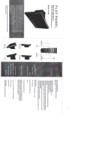
FRONT PANEL CONTROLS
Figure 6. Front Panel Controls
ì
Menu: Displays the main on-screen menu.
î
Source: Selects the input source and confirms your choice.
ï
▼and ▲: Navigates through the on-screen menu. Also, ▲is “Auto” in RGB mode
ñ
VOL (◄ and ►): Increases or decreases the volume. Also selects or adjusts items in the on-screen menu.
ó
(remote control signal receiver): Receives remote control signals.
r
(power label)
s
(power button and power indicator): Turns the monitor on and off. Also indicates the power status. Red indicates that the power is off;
blue/green indicates that the power is on.
MENU SOURCE VOL

14 C2927M-D (9/09)
REMOTE CONTROL FUNCTIONS
Figure 7. Remote Control
ì
POWER: Turns the monitor on and off.
î
AUTO: Selects auto adjustment of the screen in RGB mode.
ï
(◄/VOL– and /VOL+►, ▲,▼): Increases and decreases the volume. The up and down arrows let you move
the cursor up and down in the on-screen menu.
ñ
ASPECT: (PMCL319W only.) Changes the screen’s scan mode (4:3, 16:9).
ó
ENTER: Confirms (store or enter) your choice in the on-screen menu.
r
MENU/EXIT: Displays/exits the on-screen menu.
s
(input source): Displays all the available input sources. Press the button to select the desired input source.
t
MUTE: Temporarily silences the sound. To return the sound, press MUTE again.
ENTER
MUTE
VIDEO1
POWER
VIDEO 2
RGB DVI
MENU/EXIT AUTO
ASPECT
S-VIDEO
/VOL
/VOL +

C2927M-D (9/09) 15
ON-SCREEN DISPLAY FUNCTION
The PMCL400 Series on-screen display (OSD) lets you easily change the basic functions of the monitor from the front panel or the remote control.
Figure 8 shows how to change the input source by accessing the menu using the OSD function. The input source name appears in the upper-right
corner of the menu screen any time the input source is changed or when you press ENTER on the remote control.
Figure 8. Input Source Name Display
To access the menus:
1. Press the MENU button to access the main menu.
2. Use the up and down arrow buttons (▲,▼) to highlight a selection.
3. Use the left and right arrow buttons (◄, ►) to adjust the setting on a selected item.
VIDEO 1
VIDEO 1/2
S-VIDEO
RGB
DVI

16 C2927M-D (9/09)
VIDEO 1, VIDEO 2, S-VIDEO MODE MENU
Figure 9. Video 1, Video 2, S-Video Mode Menu
MAIN MENU
Input Menu
Contrast Menu
0 100
Brightness Menu
Color Menu
Sharpness Menu
Tint Menu
RESTORE
INFORMATION
OSD Setting Menu
Color Temperature Menu
User Menu
RESTORE
G-Gain Menu
R-Gain Menu
OSD Setting Menu
OSD V Position
OSD H Position
OSD Dwelling Time
3D Noise Reduction Menu
Language Menu
ISM Menu
0 100
0 100
0 100
0 100
ON OFF
0 8
0 100
0 100
0 100
0 100
B-Gain Menu
Reset Setting
0 100
OFF
5 30
INPUT
CONTRAST
BRIGHTNESS
COLOR
SHARPNESS
TINT
3D NOISE REDUCTION
LANGUAGE
OSD SETTING
COLOR TEMPERATURE
ISM
EDGE ENHANCEMENT
DYNAMIC CONTRAST
DEFAULT SETTING
INFORMATION
ENGLISH
ITALIAN
FRENCH
SPANISH
GERMAN
PORTUGUESE
RUSSIAN
CHINESE
OFF
NORMAL
STRONG
Edge Enhancement Menu
OFF
ON
Dynamic Contrast Menu
Default Setting Menu
OFF
ON
OSD H. POSITION
OSD V. POSITION
OSD DISPLAY TIME
R-GAIN
G-GAIN
B-GAIN
RESET
SETUP
NORMAL
COOL
USER
VIDEO 1
VIDEO 2
S-VIDEO
RGB
DVI

C2927M-D (9/09) 17
The Video 1, Video 2, S-Video Mode menu contains the following features:
Input: Changes the video input option. Select VIDEO 1, VIDEO 2, or S-VIDEO.
Contrast: Adjusts the black level of the image (0 to 100).
Brightness: Adjusts the white level of the image (0 to 100).
Color: Adjusts the color saturation of the video signal (0 to 100).
Sharpness: Adjusts the picture softer or sharper (0 to 100).
Tint: Adjusts the range of color: green to red (0 to 100).
3-D Noise Reduction: Reduces the video signal’s background noise (NORMAL, STRONG, or OFF). NORMAL is the regular level of noise
reduction while STRONG increases the level of noise reduction.
Language: Changes the language selection. Select English, Italian, French, Spanish, German, Portuguese-Brazilian, Russian, or Chinese for the
OSD display.
OSD Setting: Select SETUP for the on-screen display. Then select one of the following:
• OSD H.POSITION: Adjusts the OSD horizontal position (0 to 100).
• OSD V.POSITION: Adjusts the OSD vertical position (0 to 100).
• OSD DISPLAY TIME: Adjusts the display time (OFF or 5 to 30 seconds). Selecting 5 or 30 determines how many seconds the display
remains on the screen when you press a button. Selecting OFF means that there is no delay.
Color Temperature: Select NORMAL, COOL, or USER. If you select USER, then select from the following:
• R-Gain: Adjusts gain for red (0 to 100).
• G-Gain: Adjusts gain for green (0 to 100).
• B-Gain: Adjusts gain for blue (0 to 100).
• Reset: Select RESTORE to return to the original color temperature settings.
ISM: (Image sticking minimization) Sets the recovery time of an LCD panel display when screen burn-in occurs (when a fixed image has been
displayed for a long time). The ISM function starts working after the power is off for 10 minutes. Select ON, OFF, or from 1 to 8 hours for the
operation period.
Edge Enhancement: Improves the edge characteristic. The default setting is OFF.
Dynamic Contrast: Improves the contrast characteristic. The default setting is ON.
Default Setting: Select RESTORE to reset the monitor to the default settings.
Information: Select INFORMATION to access Pelco headquarters information.

18 C2927M-D (9/09)
RGB AND DVI MODE MENU
Figure 10. RGB and DVI Mode Menu
DISABLE
1024 X 768
1280 X 768
1360 X 768
1366 X 768
Auto Position Menu
0 100
Phase Menu
0 100
Frequency Menu
0 100
V. Position Menu
0 100
H. Position Menu
0 100
Brightness Menu
0 100
Contrast Menu
VIDEO 1
VIDEO 2
S-VIDEO
RGB
DVI
Input Menu
INPUT
CONTRAST
BRIGHTNESS
H. POSITION
V. POSITION
FREQUENCY
PHASE
AUTO POSITION OVERRIDE
LANGUAGE
OSD SETTING
COLOR TEMPERATURE
ISM
EDGE ENHANCEMENT
DYNAMIC CONTRAST
DEFAULT SETTING
INFORMATION
MAIN MENU
RESTORE
Reset Setting
0 100
B-Gain Menu
0 100
G-Gain Menu
0 100
R-Gain Menu
5 30
OFF
OSD Dwelling Time
0 100
OSD V Position
0 100
OSD H Position
R-GAIN
G-GAIN
B-GAIN
RESET
User Menu
OSD H. POSITION
OSD V. POSITION
OSD DISPLAY TIME
OSD Setting Menu
INFORMATION
RESTORE
Default Setting Menu
OFF
ON
Dynamic Contrast Menu
OFF
ON
Edge Enhancement Menu
ON OFF
1 8
ISM Menu
NORMAL
COOL
USER
Color Temperature Menu
SETUP
OSD Setting Menu
ENGLISH
ITALIAN
FRENCH
SPANISH
GERMAN
PORTUGUESE
RUSSIAN
CHINESE
Language Menu

C2927M-D (9/09) 19
Not all menus are available for both RGB and DVI. Menus that are unavailable do not appear dimmed, while some menus that do not apply are
not shown.
The RGB and DVI mode menu contains the following features:
Input: Changes the video input option. Select RGB or DVI.
Contrast: Adjusts the black level of the image (0 to 100).
Brightness: Adjusts the white level of the image (0 to 100).
H-Position: (RGB only; dimmed in DVI mode.) Adjusts the horizontal position (0 to 100).
V-Position: (RGB only; dimmed in DVI mode.) Adjusts the vertical position (0 to 100).
Frequency: (RGB only; dimmed in DVI mode.) Adjusts the horizontal size of the screen image (0 to 100).
Phase: (RGB only; dimmed in DVI mode.) Adjusts image distortion appearing as horizontal noise on the screen (0 to 100).
Auto Position Override: Changes the display resolution. Select DISABLE, 1024 x 768, 1280 x 768, 1360 x 768, or 1366 x 768.
• This menu is enabled only when one of the listed resolution settings is selected.
• If an input signal causes problems on the screen, select a different setting.
• The Auto Position menu has no effect on resolution inputs that are not listed.
Language: Changes the language selection. Select English, Italian, French, Spanish, German, Portuguese-Brazilian, Russian, or Chinese for the
OSD display.
OSD Setting: Select SETUP for the on-screen display. Then select one of the following:
• OSD H.POSITION: Adjusts the OSD horizontal position (0 to 100).
• OSD V.POSITION: Adjusts the OSD vertical position (0 to 100).
• OSD DISPLAY TIME: Adjusts the display time (OFF or 5 to 30 seconds). Selecting 5 or 30 determines how many seconds the display
remains on the screen after you press a button. Selecting OFF means no delay.
Color Temperature: Select NORMAL, COOL, or USER. NORMAL is the regular color level while COOL decreases the color level. If you select
USER, then select from the following:
• R-Gain: Adjusts gain for red (0 to 100).
• G-Gain: Adjusts gain for green (0 to 100).
• B-Gain: Adjusts gain for blue (0 to 100).
• Reset: Select RESTORE to return to the original color temperature settings.
(Image sticking minimization): Sets the recovery time of an LCD panel display when screen burn-in occurs (when a fixed image has been
displayed for a long time). The ISM function starts working after the power is off for 10 minutes. Select ON, OFF, or from 1 to 8 hours for the
operation period.
Edge Enhancement: Improves the edge characteristic. The default setting is OFF.
Dynamic Contrast: Improves the contrast characteristic. The default setting is ON.
Default Setting: Select RESTORE to reset the monitor to the default settings.
Information: Select INFORMATION to access Pelco headquarters information.

20 C2927M-D (9/09)
Troubleshooting
If the following instructions fail to solve your problem, contact Pelco Product Support at 1-800-289-9100 (USA and Canada) or +1-559-292-1981
(international) for assistance. Be sure to have the serial number available when calling.
Do not try to repair the unit yourself. Opening it immediately voids the warranty. Leave maintenance and repairs to qualified technical personnel
only. Refer to the Product Warranty and Return Information located on the inside back page of this document.
Maintenance
Periodically, you might need to clean the PMCL400 Series monitor to maintain optimum viewing performance. Be sure to observe the following
cleaning instructions to avoid damage to the monitor:
• Gently wipe your screen with a clean camel-hair brush or a soft, clean, lint-free cloth.
• Gently apply pressure to the screen surface to clean the display.
• Do not spray any liquid directly on the screen or the LCD monitor casing. Chemical cleaners can damage the screen and the LCD monitor
casing.
WARNING: To reduce the risk of electrical shock, do not remove the cover or back of the monitor. There are no user-serviceable parts are
inside.
Table A. Troubleshooting the PMCL400 Series Monitor
Problem Possible Cause Suggested Resolution
Poor picture quality Faulty system or cable connections. Make adjustments on the front panel control.
Inspect all system connections and cables.
/