Page is loading ...

Graco Inc. P.O. Box 1441 Minneapolis, MN 55440-1441
Copyright 2004, Graco Inc. is registered to I.S. EN ISO 9001
Installation and Operation
Fire-Ball
®
225, 300, and 425 Oil Pumps
For non-corrosive and non-abrasive oils
and lubricants only.
Mini Fire-Ball 225, 3:1
Parts 246775 and 248097
540 psi (3.7 MPa, 37 bar) Maximum Working Pressure
180 psi (1.24 MPa, 12.4 bar) Maximum Air Input Pressure
Fire-Ball 300, 5:1
Parts 203876, 203872, 203857, 204254, and 222087
900 psi (6.2 MPa, 62 bar) Maximum Working Pressure
180 psi (1.24 MPa, 12.4 bar) Maximum Air Input Pressure
Fire-Ball 425, 10:1
Parts 205626, 222065, and 222095
1800 psi (12.4 MPa, 124 bar) Maximum Working Pressure
180 psi (1.24 MPa, 12.4 bar) Maximum Air Input Pressure
Important Safety Instructions
Read all warnings and instructions in this manual.
Save these instructions.
309868B
Mascott Equipment Co
Portland Seattle Pasco
(800) 452-5019 (800) 481-7311 (888) 450-7867

Contents
2 Installation and Operation
Contents
Contents . . . . . . . . . . . . . . . . . . . . . . . . . . . . . . . . . . 2
Packages . . . . . . . . . . . . . . . . . . . . . . . . . . . . . . . . . 3
Manual Conventions . . . . . . . . . . . . . . . . . . . . . . . . 4
Warning . . . . . . . . . . . . . . . . . . . . . . . . . . . . . . . . . . . 5
Installation . . . . . . . . . . . . . . . . . . . . . . . . . . . . . . . . 6
Mounting the Pump . . . . . . . . . . . . . . . . . . . . . . . 7
Grounding . . . . . . . . . . . . . . . . . . . . . . . . . . . . . . 7
Mobil Mounting . . . . . . . . . . . . . . . . . . . . . . . . . 13
Operation . . . . . . . . . . . . . . . . . . . . . . . . . . . . . . . . 15
Relieving Pressure . . . . . . . . . . . . . . . . . . . . . . 15
Starting and Adjusting the Pump . . . . . . . . . . . 15
Parts . . . . . . . . . . . . . . . . . . . . . . . . . . . . . . . . . . . . 16
Universal Pump Package
Fire-Ball 225 Model 248230
Fire-Ball 300 Model 225852
Fire-Ball 425 Model 225853 . . . . . . . . . . . . 16
16-gallon (60 Liter) Gear Lube Dispenser
Fire-Ball 225 Model 246903
Fire-Ball 300 Model 225728 . . . . . . . . . . . . 18
16-gallon (60 Liter) Drum Cover Pump
Fire-Ball 225 Model 246904
Fire-Ball 300 Model 225094 . . . . . . . . . . . . 20
55-gallon (208 Liter) Drum Cover Pump
Fire-Ball 225 Model 246906
Fire-Ball 300 Model 225642
Fire-Ball 425 Model 225782 . . . . . . . . . . . . 22
55-/275-gallon (208 Liter) Drum Bung-Mount Pump
Fire-Ball 225 Model 246907
Fire-Ball 300 Model 225640
Fire-Ball 300 Model 225931
Fire-Ball 425 Model 225786 . . . . . . . . . . . . 24
16-gallon (60 Liter) Drum Cover, Truck Mounted
Pump
Fire-Ball 300 Model 222086 . . . . . . . . . . . . 26
55-gallon (208 Liter) Drum Cover, Truck Mounted
Pump
Fire-Ball 300 Model 206655
Fire-Ball 425 Model 206656 . . . . . . . . . . . . 27
55-gallon (208 Liter) Bung Adapter, Truck Mounted
Pump
Fire-Ball 300 Model 204264
Fire-Ball 425 Model 222067 . . . . . . . . . . . . 28
Technical Data . . . . . . . . . . . . . . . . . . . . . . . . . . . . 30
Fire-Ball 225 (3:1) . . . . . . . . . . . . . . . . . . . . . . . 30
Fire-Ball 300 (5:1) . . . . . . . . . . . . . . . . . . . . . . . 30
Fire-Ball 425 (10:1) . . . . . . . . . . . . . . . . . . . . . . 30
Dimensions . . . . . . . . . . . . . . . . . . . . . . . . . . . . . . . 31
Fire-Ball 225 . . . . . . . . . . . . . . . . . . . . . . . . . . . 31
Fire-Ball 300 . . . . . . . . . . . . . . . . . . . . . . . . . . . 32
Fire-Ball 425 . . . . . . . . . . . . . . . . . . . . . . . . . . . 33
Graco Standard Warranty . . . . . . . . . . . . . . . . . . . 34
Graco Information . . . . . . . . . . . . . . . . . . . . . . . 34
Additional Reference Manuals
This manual covers the installation and operation of Graco Fire-Ball pumps. For information on service and repair of
these pumps, please see the following manual.
• Fire-Ball Pump Service, Troubleshooting, and Repair 309869.
You should also read the instruction manuals for all components of your system.

Packages
Installation and Operation 3
Packages
Model/
Package No. Pump Description
Hose/
Fitting Kit
Cover/Bung
Adapter
Dispense
Kit
Air
Regulator
Fire-Ball 225 Packages
248230
246775 Universal
222062
246903
248097
16 gallon (60 liter), gear lube 204574 237075 224512
246904
248097 16 gallon (60 liter), drum
cover 222063 204574 224512
246906
248097 55 gallon (208 liter), drum
cover 222063 200326 224512
246907
248097 55/275 gallon (208/1041 liter),
bung mount 222063 222308
Fire-Ball 300 Packages
225852
203876
Universal 222062
225728
203872
16 gallon (60 liter), gear lube 204574 237075 224512
225094
203872 16 gallon (60 liter), drum
cover 222063 204574
225642
203857 55 gallon (208 liter), drum
cover 222063 200326
225640
204254 55 gallon (208 liter), bung
mount 222063 222308
225931
222087 275 gallon (1041 liter)
obround tank 222063 222308
222086
203872 16 gallon (60 liter), drum
cover, truck mount 222063 222060
206655
203857 55 gallon (208 liter) drum
cover, truck mount 222063 207367
204264
204254 55 gallon (208 liter) bung
adapter, truck mount 222063 204076
Fire-Ball 425 Packages
225853
205626
Universal 222068
225782
222065 55 gallon drum (208 liter),
drum cover 222066 200326
225786
222095 55 gallon (208 liter), bung
adapter 222066 222308
206656
222065 55 gallon (208 liter) drum
cover, truck mount 222066 207367
222067
222095 55 gallon (208 liter) bung
adapter, truck mount 222066 224579

Manual Conventions
4 Installation and Operation
Manual Conventions
Warning Caution
Note
WARNING
A warning alerts you to possible serious injury or
death if you do not follow instructions.
Symbols, such as fire and explosion (shown), alert you
to a specific hazard and direct you to read the indi-
cated hazard warnings beginning on page 4.
CAUTION
A caution alerts you to possible equipment damage or
destruction if you do not follow instructions.
A note indicates additional helpful information.
WARNINGS
EQUIPMENT MISUSE HAZARD
Misuse can cause death or serious injury.
• Do not exceed the maximum working pressure or temperature rating of the lowest rated system
component. See Technical Data in all equipment manuals.
• Use fluids and solvents that are compatible with equipment wetted parts. See Technical Data in
all equipment manuals. Read fluid and solvent manufacturer’s warnings.
• Check equipment daily. Repair or replace worn or damaged parts immediately.
• Do not alter or modify equipment.
• Use equipment only for its intended purpose. Call your Graco distributor for information.
• For professional use only.
• Route hoses and cables away from traffic areas, sharp edges, moving parts, and hot surfaces.
• Do not use hoses to pull equipment.
• Comply with all applicable safety regulations.
PRESSURIZED EQUIPMENT HAZARD
Fluid from the gun/dispense valve, leaks, or ruptured components can splash in the eyes or on skin
and cause serious injury.
• Follow Pressure Relief Procedure in this manual, when you stop spraying and before cleaning,
checking, or servicing equipment.
• Tighten all fluid connections before operating the equipment.
• Check hoses, tubes, and couplings daily. Replace worn or damaged parts immediately.

Warning
Installation and Operation 5
WARNING
SKIN INJECTION HAZARD
High-pressure fluid from gun, hose leaks, or ruptured components will pierce skin. This may look like just
a cut, but it is a serious injury that can result in amputation. Get immediate surgical treatment.
• Do not point gun at anyone or at any part of the body.
• Do not put your hand over the spray tip.
• Do not stop or deflect leaks with your hand, body, glove, or rag.
• Do not spray without tip guard and trigger guard installed.
• Engage trigger lock when not spraying.
• Follow Pressure Relief Procedure in this manual, when you stop spraying and before cleaning,
checking, or servicing equipment.
MOVING PARTS HAZARD
Moving parts can pinch or amputate fingers and other body parts.
• Keep clear of moving parts.
• Do not operate equipment with protective guards or covers removed.
• Pressurized equipment can start without warning. Before checking, moving, or servicing equipment,
follow the Pressure Relief Procedure in this manual. Disconnect power or air supply.
TOXIC FLUID OR FUMES HAZARD
Toxic fluids or fumes can cause serious injury or death if splashed in the eyes or on skin, inhaled, or
swallowed.
• Read MSDS’s to know the specific hazards of the fluids you are using.
• Store hazardous fluid in approved containers, and dispose of it according to applicable guidelines.
FIRE AND EXPLOSION HAZARD
Flammable fumes, such as solvent and paint fumes, in work area can ignite or explode. To help prevent
fire and explosion:
• Use equipment only in well ventilated area.
• Eliminate all ignition sources; such as pilot lights, cigarettes, portable electric lamps, and plastic drop
cloths (potential static arc).
• Keep work area free of debris, including solvent, rags and gasoline.
• Do not plug or unplug power cords or turn lights on or off when flammable fumes are present.
• Ground equipment and conductive objects. See Grounding instructions.
• Use only grounded hoses.
• Hold gun firmly to side of grounded pail when triggering into pail.
• If there is static sparking or you feel a shock, stop operation immediately. Do not use equipment
until you identify and correct the problem.

Installation
6 Installation and Operation
Installation
The typical stationary installation shown in is only a
guide for selecting and installing a pump; it is not an
actual system design. Contact your Graco distributor for
assistance in designing a system to meet your needs.
.
Letters used to identify components in FIG. 1 are
referred to in the package installation drawings,
F
IG. 3 through FIG. 7. Additional letter references
are used in installation drawings as necessary.
A
B
C
D
E
F
G
H
L
J
K
M
Key
A Bleed-type master air valve
B Air line filter
C Air regulator and gauge
D Air inlet
E Ground wire
F Pump
G Drain valve
H Dispensing valve
J Fluid hose
K Thermal relief kit (235998)
L Air line lubricator
M Bung adapter
N Fluid outlet
P Extension tube
N
P
FIG. 1

Installation
Installation and Operation 7
Mounting the Pump
• Select a location that allows the operator easy
access to the pump and air controls, sufficient room
to change supply containers, and a secure mount-
ing platform.
• If you are mounting the pump directly on the supply
container, be sure it is positioned so the pump’s
intake tube is no more than 1 in. (25 mm) from the
bottom of the container. Mount the pump to the
cover or other suitable mounting device.
Grounding
Proper grounding is essential to maintaining a safe sys-
tem.
To reduce the risk of static sparking, ground the pump.
Check local electrical codes for detailed grounding
instructions for your area and equipment type. Be sure
the following equipment is properly grounded:
• Pump: See F
IG. 2
• Air and Fluid hoses: Use only electrically conductive
hoses.
• Air compressor: Follow manufacturer’s recommen-
dations.
• Dispensing valve: Obtain grounding through con-
nection to a properly grounded fluid hose and pump.
• Fluid supply container: Follow your local code.
• Object being lubricated: Follow your local code.
• Any pails used when flushing: Use only metal,
grounded pails when flushing. Make firm
metal-to-metal contact between a metal part of the
dispensing valve and the pail. Use the lowest possi-
ble pressure.
• To maintain grounding continuity when flushing or
relieving pressure, always hold a metal part of the
dispensing valve firmly to the side of a metal pail
and then open the dispensing valve.
To maintain grounding continuity when flushing or reliev-
ing pressure, always hold a metal part of the valve firmly
to the side of a grounded metal pail, then trigger the
valve.
To ground the pump, remove the ground screw (Z) and
insert through the eye of the ring terminal at end of
ground wire, (Y). Fasten the ground screw back onto the
pump and tighten securely. Connect the other end of the
ground wire to a true earth ground. See F
IG. 2. To order
a ground wire and clamp order Part No. 222011.
F
IG. 2
WARNING
Mount the pump securely so that it cannot move dur-
ing operation. Failure to do so could result in personal
injury or equipment damage.
To prevent damage to the pump, remove sedi-
ment from the bottom of the container before
installing a pump in an existing container.
Y
Z
TI1052

Installation
8 Installation and Operation
Universal Pump
Fire-Ball 225 Model 248230
Fire-Ball 300 Model 225852
Fire-Ball 425 Model 225853
1. Apply thread sealant to the male threads of the 3/8
npt swivel union (2d). Screw the union into the pump
air inlet (D).
2. Apply thread sealant to the male threads of the 1/2
npt swivel union (2b). Screw the union into the pump
fluid outlet (N).
3. Connect the 1/2 npt(mbe) fluid hose (2a) to the
swivel union (2b).
4. Connect the 3/8 npt(mbe) air hose (2c) to the swivel
union (2d).
F
IG. 3
2b
2a
2d
2c
N
D
F

Installation
Installation and Operation 9
16-Gallon (60 Liter) Gear Lube Dispenser
Fire-Ball 225 Model 246903
Fire-Ball 300 Model 225728
1. Assemble the base (5) as shown in FIG. 4. Place an
opened 16-gallon (60 liter) drum on the base and
secure it with the hold-down clamps. Tighten the
hold-down clamp bolts
2. For 246903, cut the extension tube (P) at a 45°
angle to a length appropriate for the size of the
drum. When installed, the bottom of the angle
should be about 1” (25 mm) from the bottom of the
drum. The down tube for 225728 is sized for the
container.
3. Set the cover (4) on the drum and secure the
thumbscrews (Q). Install the pump (F) on the cover
(4) with the screws (R), washers and nuts (S) pro-
vided
4. Connect the hose (2a) to the pump fluid outlet (N).
F
IG. 4
F
3c
D
3d
3b
3d
R
2a
2b
S
5
Q
4
3a
N
P

Installation
10 Installation and Operation
16-Gallon (60 Liter) Drum Cover Pump
Fire-Ball 225 Model 246904
Fire-Ball 300 Model 225094
1. Set the cover (4) on a 16-gallon (60 liter) drum and
secure with the thumbscrews (Q). See F
IG. 5.
2. For 246904 cut the extension tube (P) at a 45° angle
to a length appropriate for the size of the drum.
When installed, the bottom of the angle should be
about 1” (25 mm) from the bottom of the drum. The
down tube for 225094 is sized for the container.
3. Install the pump (F) on the cover (4) with the screws
(R), washers and nuts (S) supplied.
4. Assemble the air regulator kit (items 3a-3d) to the
pump air inlet (D) as shown. Use thread sealant and
tighten all parts securely.
5. Apply thread sealant to the male threads of the 3/8
npt swivel union (2d). Screw the union into the
bleed-type master air valve (3c).
6. Apply thread sealant to the male threads of the 1/2
npt swivel union (2b). Screw the union into the pump
fluid outlet (N).
7. Connect the 1/2 npt(mbe) fluid hose (2a) to the
swivel union (2b).
8. Connect the 3/8 npt(mbe) air hose (2c) to the swivel
union (2d).
F
IG. 5
2b
2a
2d
2c
F
3d
3b
3d
3c
4
Q
3a
D
R
A
N
P
S

Installation
Installation and Operation 11
55-Gallon (208 Liter) Drum Cover Pump
Fire-Ball 225 Model 246906
Fire-Ball 300 Model 225642
Fire-Ball 425 Model 225782
1. For 246906 cut the extension tube (P) at a 45° angle
to a length appropriate for the size of the drum.
When installed, the bottom of the angle should be
about 1” (25 mm) from the bottom of the drum. For
225642 and 225782 the down tube is sized for the
container.
2. Set the cover (4) on a 55-gallon (208 liter) drum.
Install the pump (F) on the cover with the screws (R)
supplied. See F
IG. 6
3. Assemble the air regulator kit (items 3a-3d) to the
pump air inlet (D) as shown. Use thread sealant and
tighten all parts securely.
4. Apply thread sealant to the male threads of the 3/8
npt swivel union (2d). Screw the union into the
bleed-type master air valve (3c).
5. Apply thread sealant to the male threads of the 1/2
npt swivel union (2b). Screw the union into the pump
fluid outlet (N).
6. Connect the 1/2 npt(mbe) fluid hose (2a) to the
swivel union (2b).
7. Connect the 3/8 npt(mbe) air hose (2c) to the swivel
union (2d).
F
IG. 6
2b
2a
2d
2c
F
3d
3b
3d
3a
3c
4
D
N
R
P

Installation
12 Installation and Operation
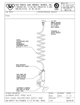
55-/275-Gallon (208 Liter) Drum,
Bung-Mount Pump
Fire-Ball 225 Model 246907
Fire-Ball 300 Models 225640 and 225931
1. Screw the bung adapter (M) into the bung hole of
the drum. See F
IG. 7.
2. For 246907 cut the extension tube (P) at a 45° angle
to a length appropriate for the size of the drum.
When installed, the bottom of the angle should be
about 1” (25 mm) from the bottom of the drum. For
224640 and 225931 the down tube is sized for the
container.
3. Tighten the bung adapter screw (T) to hold the
pump in position.
4. Apply thread sealant to the male threads of the 3/8
npt swivel union (2d). Screw the union into the pump
air inlet (D).
5. Apply thread sealant to the male threads of the 1/2
npt swivel union (2b). Screw the union into the pump
fluid outlet (N).
6. Connect the 1/2 npt(mbe) fluid hose (2a) to the
swivel union (2b).
7. Connect the 3/8 npt(mbe) air hose (2c) to the swivel
union (2d).
F
IG. 7
2b
2d
N
F
2a
2c
T
M
D
P
Model 225931

Installation
Installation and Operation 13
Mobil Mounting
Mobil Mounting Layout
Plan the layout for easy operator access to the pump air
controls, sufficient space to change drums, and a
secure mounting platform.
Drum Mounting
1. Place the drum in the desired location.
2. Place the hold-down lugs (Y) or drum locators (X)
around the drum base and bolt directly to the truck
bet or mounting platform. See F
IG. 8.
F
IG. 8
Open Drum, Cover-Mounted Pumps
1. Remove the original drum cover.
2. Mount the new drum cover and fasten in place.
3. Guide the pump extension tube through the mount-
ing gasket.
4. Align the drum cover eyelets (T) with the hold-down
rods (W), install the cover brackets (V) and wing
nuts (U) and tighten securely. See F
IG. 8.
Closed Bung-Type-Drum, Cover-Mounted
Pump
1. Insert the pump extension tube through the gasket
(Z) and drum cover (AA). Fasten the Fire-Ball 300
from the top and the Fire-Ball 425 from the bottom.
See F
IG. 9.
2. Slide the rubber grommet (BB), tapered end down,
onto the extension tube and push it up against the
pump base. See F
IG. 9.
3. Guide the pump extension tube through the drum
bung hole (CC) and place the cover on the drum.
See F
IG. 9.
4. Align the drum cover eyelets (T) with the hold-down
rods (W), install the hold-down brackets (V) and
wing nuts (U) and tighten securely. See F
IG. 8.
F
IG. 9
T Drum cover eyelets
U Wing nuts
V Hold-down brackets
W Hold-down rods
X Drum locators
Y Hold-down rod lugs
T
U
V
W
X
Y
Z Gasket
AA Drum cover
BB Grommet
CC Bung Hole
Z
AA
BB
CC

Installation
14 Installation and Operation
Closed Bung-Type-Drum,
Sturdi-Clamp-Mounted Pumps
1. Remove the adjustable bung adapter fro the pump
extension tube.
2. Screw the bung adapter (HH) into the bung hole.
3. Loosen the wing nuts (EE) and slide the clamp (DD)
onto the pump extension tube, up to the base. See
F
IG. 10.
4. Holding the clamp onto the pump, insert the pump
extension tube through the bung adapter, and lower
the pump until the clamp rests on the edge of the
drum. See F
IG. 10.
5. Install the sturdi-clamp so its upper jaw fits against
the pump base projection, its u-bolt (GG) fits around
the extension tube, and its lower jaw fits against the
bung adapter. Tighten the wing nuts (EE). See F
IG.
10.
6. Tighten the T-handle (FF) firmly to the side of the
drum.
F
IG. 10
DD Clamp
EE Wing Nuts
FF T-handle
GG U-bolt
HH Bung adapter
DD
FF
GG
HH
EE

Operation
Installation and Operation 15
Operation
See FIG. 1 to identify references shown in parentheses,
i.e.,(A).
Relieving Pressure
1. Close the pump air regulator (C) and the bleed-type
master air valves (A) (required in your system).
2. Hold a metal part of the dispensing valve (H) firmly
to a grounded metal waste container, and trigger the
valve to relieve the fluid pressure.
Starting and Adjusting the Pump
1. With the air regulator (C) closed, open the
bleed-type master air valve (A).
2. Open the dispensing valve (H) into a grounded
metal waste container, making firm metal-to-metal
contact between the container and valve.
3. Open the pump air regulator (C) slowly, just until the
pump is running. When the pump is primed and all
air has been pushed out of the lines, close the dis-
pensing valve (H).
NOTE: When the pump is primed, and with sufficient air
supplied, the pump starts when the dispensing valve (H)
is opened, and shuts off when it is closed.
4. Adjust the air regulator (C) until you get sufficient
flow from dispensing valve (H). Always run the
pump at the lowest pressure necessary to get the
desired results. Do not exceed the maximum work-
ing pressure of any component in the system.
5. If your pump accelerates quickly or is running too
fast, stop it immediately and check the fluid supply. If
the supply container is empty and air has been
pumped into the lines, prime the pump and lines
with fluid, or flush it and leave it filled with a compat-
ible solvent. Be sure to eliminate all air from the fluid
lines.
6. Read and follow the instructions supplied with each
component in your system.
7. If the pump will be unattended for any period of
time, if there is an air supply interruption, or at the
end of the work shift, shut off the system and always
relieve the pressure.
WARNING
This equipment stays pressurized until pressure is
manually relieved. Read PRESURIZED EQUIPMENT
HAZARD warnings on page 4.
Maximum working pressure of all components in the
system may not be the same. To reduce risk of over-
pressurizing any component, be sure you know the
maximum working pressure of each component.
Never exceed the maximum working pressure of the
lowest rated component in the system. Overpressuriz-
ing any component can result in rupture, fire, explo-
sion, property damage, and serious injury.
To determine the fluid output pressure using the air
regulator reading, multiply the ratio of the pump by the
air pressure shown on the regulator gauge. For exam-
ple:
3 (:1) ratio x 100 psi air = 300 psi fluid output
Limit the air pressure to the pump so that no air line or
fluid line component is overpressurized.
WARNING
Read the MOVING PARTS HAZARD and TOXIC
FLUID OR FUMES warnings on page 5
CAUTION
Never allow the pump to run dry of the fluid being
pumped. A dry pump will quickly accelerate to a high
speed, possibly causing pump damage. It may also get
very hot.

Parts
16 Installation and Operation
Parts
Universal Pump Package
Fire-Ball 225 Model 248230
Fire-Ball 300 Model 225852
Fire-Ball 425 Model 225853
2b
2a
2d
2c
1

Parts
Installation and Operation 17
Parts List
Ref.
No. Part No. Description Qty.
1 246775 PUMP, Mini-Fire-Ball 225 3:1,
universal; (for 248230, see 309869
for parts)
1
203876 Pump, Fire-Ball 300 5:1,
universal; (for 225852, see 309869
for parts)
1
205626 Pump, Fire-Ball 425 10:1,
universal; (for 225853, see 309869
for parts
1
2 222062 HOSE AND FITTING KIT;
(for 248230 and 225852) Includes
items 2a-2d
1
222068 HOSE AND FITTING KIT;
(for 225853) Includes items 2a-2d
1
2a 220598
•FLUID HOSE,1/2’ ID, cpld
1/2-14 npt(m), 18 in. (457 mm) (for
222062)
1
109108
•FLUID HOSE, (for 222068) 1
2b 155470
•UNION, swivel, 90°; 1/2 npt(m) x
1/2 npsm(f) (for 222062)
1
160327
•UNION, 90°, 3/4-14 (for 222068) 1
2c 204560
•AIR HOSE, 3/8 in. ID, cpld
3/8-18 npt(m), 18 in. (457 mm)
(for 222062)
1
218093
•AIR HOSE, (for 222068) 1
2d 155494
•UNION, swivel, 90°; 3/8 npt(m) x
3/8 npsm(f) (for 222062)
1
155470
•UNION, swivel, 90°; 1/2 npt(m) x
1/2 npsm(f)
(for 222068)
1
Ref.
No. Part No. Description Qty.

Parts
18 Installation and Operation
16-gallon (60 Liter) Gear Lube Dispenser
Fire-Ball 225 Model 246903
Fire-Ball 300 Model 225728
1
3c
3d
3b
3d
2a
2b
5
4
3a

Parts
Installation and Operation 19
Parts List
Ref.
No. Part No. Description
Qty.
1 248097 PUMP, Mini-Fire-Ball 225 3:1,
multi-length; (for 246903, see
309869 for parts)
1
203872 PUMP, Fire-Ball 300 5:1; (for
225728, see 309869 for parts)
2 237075 DISPENSE KIT;
Included items 2a and 2b
See manual 307884
1
2a 220591
• HOSE, coupled, 6 ft.
(1/2 in. npt (mbe)
1
2b 238463
• VALVE, dispense 1
3 224512 AIR REGULATOR KIT
Includes items 3a-3d
1
3a 110234
• REGULATOR, air; 3/8 npt(f)
0-250 psi
0-1.7 MPa, 0-14.4 bar) range
See manual 308167
1
3b 100960
• GAUGE, air pressure 1
3c 110224
• VALVE, air, bleed-type; 3/8 npt(f)
1
3d 156849
• NIPPLE, 3/8 npt
2
4 204574 COVER, drum;
See manual 306345 for parts
1
5 203622 PORTABLE BASE;
See manual 308668 for parts
1

Parts
20 Installation and Operation
16-gallon (60 Liter) Drum Cover Pump
Fire-Ball 225 Model 246904
Fire-Ball 300 Model 225094
2b
2a
2d
2c
1
3d
3b
3d
3c
4
3a
/