2
USING THE UNIT SAFELY
001
• Before using this unit, make sure
to read the instructions below,
and the Owner’s Manual.
.......................................................................
002c
• Do not open (or modify in any
way) the unit or its AC adaptor.
.......................................................................
003
• Do not attempt to repair the unit,
or replace parts within it (except
when this manual provides
specific instructions directing
you to do so). Refer all servicing
to your retailer, the nearest
Roland Service Center, or an
authorized Roland distributor, as
listed on the “Information” page.
.......................................................................
004
• Never use or store the unit in
places that are:
• Subject to temperature
extremes (e.g., direct sunlight
in an enclosed vehicle, near a
heating duct, on top of heat-
generating equipment); or are
• Damp (e.g., baths, washrooms, on wet
floors); or are
• Humid; or are
• Exposed to rain; or are
• Dusty; or are
• Subject to high levels of vibration.
.......................................................................
007
• Make sure you always have the
unit placed so it is level and sure
to remain stable. Never place it
on stands that could wobble, or
on inclined surfaces.
.......................................................................
008b
• Use only the specified AC
adaptor (PSA series), and make
sure the line voltage at the instal-
lation matches the input voltage
specified on the AC adaptor’s
body. Other AC adaptors may
use a different polarity, or be
designed for a different voltage,
so their use could result in
damage, malfunction, or electric
shock.
......................................................................
009
• Do not excessively twist or bend
the power cord, nor place heavy
objects on it. Doing so can
damage the cord, producing
severed elements and short
circuits. Damaged cords are fire
and shock hazards!
......................................................................
011
• Do not allow any objects (e.g.,
flammable material, coins, pins);
or liquids of any kind (water, soft
drinks, etc.) to penetrate the unit.
......................................................................
013
• In households with small
children, an adult should
provide supervision until the
child is capable of following all
the rules essential for the safe
operation of the unit.
......................................................................
014
• Protect the unit from strong
impact.
(Do not drop it!)
......................................................................
016
• Before using the unit in a foreign
country, consult with your
retailer, the nearest Roland
Service Center, or an authorized
Roland distributor, as listed on
the “Information” page.
......................................................................
012c
• Immediately turn the power off,
remove the AC adaptor from the
outlet, and request servicing by
your retailer, the nearest Roland
Service Center, or an authorized
Roland distributor, as listed on
the “Information” page when:
• The AC adaptor or the power-
supply cord has been
damaged; or
• If smoke or unusual odor occurs
• Objects have fallen into, or liquid has
been spilled onto the unit; or
• The unit has been exposed to rain (or
otherwise has become wet); or
• The unit does not appear to operate
normally or exhibits a marked change
in performance.
.......................................................................
015
• Do not force the unit’s power-
supply cord to share an outlet
with an unreasonable number of
other devices. Be especially
careful when using extension
cords—the total power used by
all devices you have connected to
the extension cord’s outlet must
never exceed the power rating
(watts/amperes) for the
extension cord. Excessive loads
can cause the insulation on the
cord to heat up and eventually
melt through.
.......................................................................
019
• Batteries must never be
recharged, heated, taken apart, or
thrown into fire or water.
.......................................................................
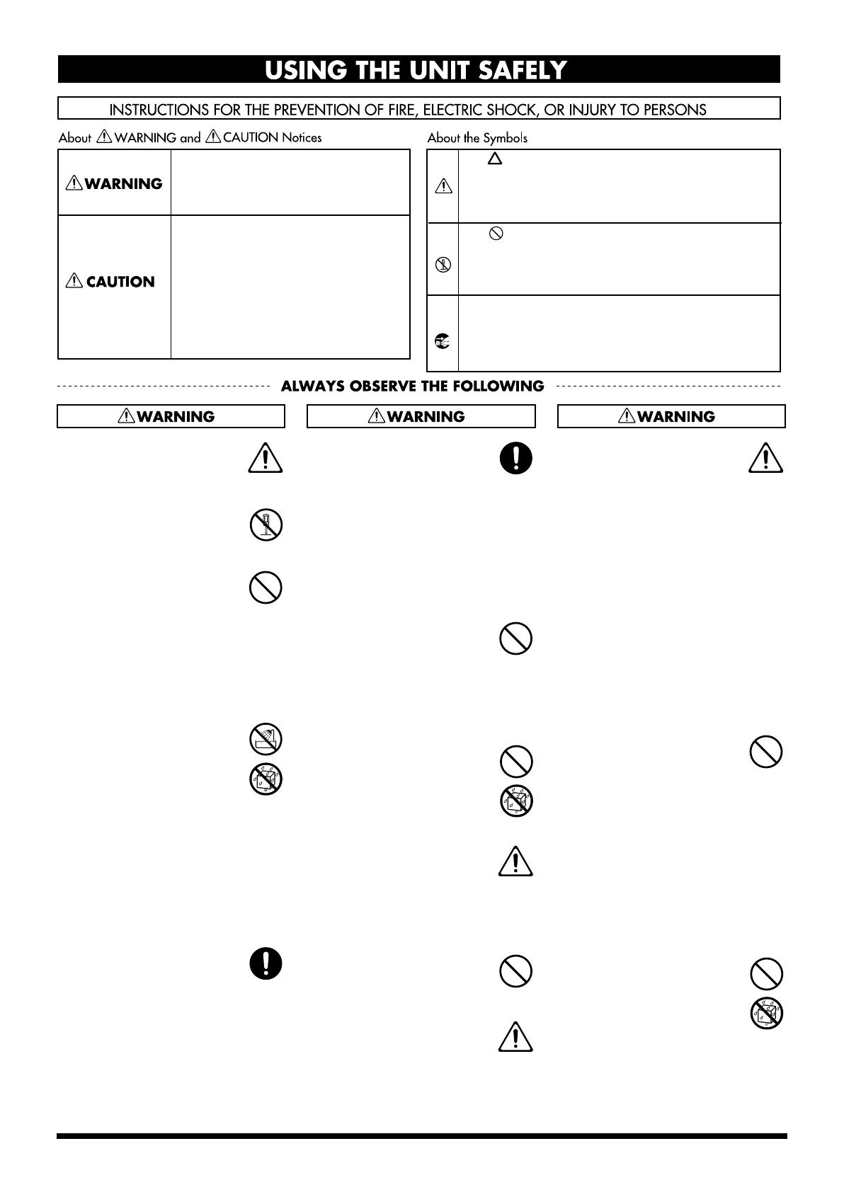
Used for instructions intended to alert
the user to the risk of injury or material
damage should the unit be used
improperly.
* Material damage refers to damage or
other adverse effects caused with
respect to the home and all its
furnishings, as well to domestic
animals or pets.
Used for instructions intended to alert
the user to the risk of death or severe
injury should the unit be used
improperly.
The ● symbol alerts the user to things that must be
carried out. The specific thing that must be done is
indicated by the design contained within the circle. In
the case of the symbol at left, it means that the power-
cord plug must be unplugged from the outlet.
The symbol alerts the user to important instructions
or warnings.The specific meaning of the symbol is
determined by the design contained within the
triangle. In the case of the symbol at left, it is used for
general cautions, warnings, or alerts to danger.
The symbol alerts the user to items that must never
be carried out (are forbidden). The specific thing that
must not be done is indicated by the design contained
within the circle. In the case of the symbol at left, it
means that the unit must never be disassembled.
FC-300_e2.book 2 ページ 2007年10月4日 木曜日 午後5時22分


