

2
PCY60
IMPORTANT NOTICE
This manual has been provided for the use of authorized Yamaha Retailers and their service personnel. It has been assumed that
basic service procedures inherent to the industry, and more specifically Yamaha Products, are already known and understood by the
users, and have therefore not been restated.
WARNING: Failure to follow appropriate service and safety procedures when servicing this product may result in personal injury,
destruction of expensive components, and failure of the product to perform as specified. For these reasons, we
advise all Yamaha product owners that all service required should be performed by an authorized Yamaha Retailer
or the appointed service representative.
IMPORTANT: The presentation or sale of this manual to any individual or firm does not constitute authorization, certification or
recognition of any applicable technical capabilities, or establish a principle-agent relationship of any form.
The data provided is believed to be accurate and applicable to the unit(s) indicated on the cover. The research, engineering, and
service departments of Yamaha are continually striving to improve Yamaha products. Modifications are, therefore, inevitable and
changes in specification are subject to change without notice or obligation to retrofit. Should any discrepancy appear to exist, please
contact the distributor's Service Division.
WARNING: Static discharges can destroy expensive components. Discharge any static electricity your body may have
accumulated by grounding yourself to the ground buss in the unit (heavy gauge black wires connect to this buss).
IMPORTANT: Turn the unit OFF during disassembly and part replacement. Recheck all work before you apply power to the unit.
WARNING: CHEMICAL CONTENT NOTICE!
The solder used in the production of this product contains LEAD. In addition, other electrical/electronic and /or plastic (where applicable)
components may also contain traces of chemicals found by the California Health and Welfare Agency (and possibly other entities) to
cause cancer and/or birth defects or other reproductive harm.
DO NOT PLACE SOLDER, ELECTRICAL/ELECTRONIC OR PLASTIC COMPONENTS IN YOUR MOUTH FOR ANY REASON WHAT-
SOEVER!
Avoid prolonged, unprotected contact between solder and your skin! When soldering, do not inhale solder fumes or expose eyes to
solder/flux vapor!
If you come in contact with solder or components located inside the enclosure of this product, wash your hands before handling food.
External Dimensions
Weight
Controls
Output connectors
Accessories
SPECIFICATIONS
295 (W) x 234 (D) x 36 (H) mm
430 g
Output Level adjustment knob
Regular 0.25-inch phone jack (mono)
3-meter phone cable(mono)

PCY60
3
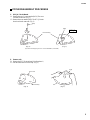
PCY60 DISASSEMBLY PROCEDURE
1. PCY JK Circuit Board
1-1
Remove the two (2) screws marked [A50]. The cover
can then be removed. (Fig. 1)
1-2
Remove the screw marked [B50]. The PCY JK circuit
board can then be removed. (Fig. 2)
2. Sensor unit
2-1
Remove the PCY JK circuit board. (See Procedure 1.)
2-2
Peel the sensor unit off of the body
. (Fig. 3)
(Fig. 1)
[50]: Bind Head Tapping Screw-P 3.0x10 MFZN2BL (VU425500)
(Fig. 2)
(Fig. 3) (Fig. 4)
[50A]
[50B]
Pad Assembly
Sensor uint
Pad Assembly
Pad
Body
PCY JK

4
PCY60
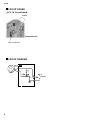
CIRCUIT BOARD
CIRCUIT DIAGRAM
CN1: to sensor uint
sensor
JK
PCY JK Circuit Board
Components side
OUTPUT
OUTPUT

PARTS LIST
CYMBAL PAD
Notes: DESTINATION ABBREVIATIONS
J: Japanese model
U: U.S. model
V: General export model (110V)
W: General export model (220V)
X: General export model
Y: Export model
A: Australian model
B: British model
C: Canadian model
E: European model
H: North European model
I: Indonesian model
CONTENTS
OVERALL ASSEMBLY………………………………………… 2
ELECTRICAL PARTS………………………………………… 3
•The numbers in "QTY" shows quantities for each unit.
•The parts with "--" in "Parts No." are not available as spare parts.
•The mark " } " in the remarks column indicates that these parts are interchangeable.
PCY60

2
PCY60
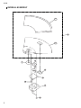
OVERALL ASSEMBLY
P10
10
P20
30
20
40
50
70
80
70
60

3
PCY60
*: New parts RANK: Japan only
REF NO.
PART NO.
DESCRIPTION REMARKS
QTY
RANK
OVERALL ASSEMBLY
*
*
*
*
10
20
30
40
50
60
70
80
P10
P20
--
--
VU424900
VT807600
VU426750
VU425300
VU425400
VU425500
--
--
V3539600
V3539700
V2638600
OVERALL ASSEMBLY
Overall Assembly
Pad Assembly
Ring Spacer
Rubber Tape
Circuit Board
Sensor Unit
Cover
Bind Head Tapping Screw-P
Name Plate
Pad Assembly
Body
Pad
ACCESSORIES
Phone Cable
25X25
PCYJK
PW 3.0X10 MFZN2BL
PCY60
(V353900)
(V353950)
(XR762B0)
(V353950)
04
03
05
06
01
07
3
*: New parts RANK: Japan only
REF NO.
PART NO.
DESCRIPTION REMARKS
QTY
RANK
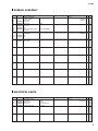
ELECTRICAL PARTS
*
R1
JK1
CN1
VR1
VU426750
HF757100
VS056300
VB389800
VA788500
ELECTRICAL PARTS
Circuit Board
Carbon Resistor
Phone Jack
Connector Base Post
Trimmer Potentiometer
PCYJK
10.0K 1/4 J
JACK HLJ7001-01-
PH- 2P TE
B 220.0K 3P RHE
PCY60
(XR762B0)
01
01
01
01
-
 1
1
-
 2
2
-
 3
3
-
 4
4
-
 5
5
-
 6
6
-
 7
7


Ask a question and I''ll find the answer in the document
Finding information in a document is now easier with AI
Related papers
-
Yamaha PCY10 Owner's manual
-
-
-
-
-
-
-
-
-
Other documents
-
Roland TD-20 User manual
-
Smartrigger CY-12H User manual
-
 Smartrigger CY-16RC3 User manual
-
 ADEUNIS Bluetooth ARF52 User guide
-
Sharp FO-2150CM User manual
-
Brother P-touch ST-1150 User manual
-
Panasonic Microwave NE-1056A User manual
-
Epson Stylus Pro 4800 Portrait Edition User manual
-
-

