
Operation, Installation & Service Manual
SSL and SSIL Series
Sight Glass Hopper Loaders
Important! Read Carefully Before Attempting to Install or Operate Equipment
Part No. 882.00149.00 Revision C Bulletin No. CV1-600

2
Write down your hopper ________________ ________________
loader serial numbers ________________ ________________
here for future reference ________________ ________________
________________ ________________
Performance figures stated in this manual are based on a standard atmosphere of 59°F
(15°C) at 29.92” Hg (1,014 millibars) at sea level, using 60 Hz power. Altitude is an
important consideration when specifying hopper loaders. ACS can advise you on proper
selection and sizing of systems for your operating environment.
ACS is committed to a continuing program of product improvement.
Specifications, appearance, and dimensions described in this manual
are subject to change without notice.
© Copyright ACS, Inc. 2005
All rights reserved. Effective 8/1/2005
Part No. Revision C Bulletin No. XX4-610C

3
Shipping Information
Unpacking and Inspection
You should inspect your SSL/CSL or SSIL/CSIL hopper loader for possible shipping damage.
If the container and packing materials are in reusable condition, save them for reshipment if
necessary.
Thoroughly check the equipment for any damage that might have occurred in transit, such as
broken or loose wiring and components, loose hardware and mounting screws, etc. In case of
breakage, damage, shortage, or incorrect shipment, refer to the following sections.
In the Event of Shipping Damages
Important!
According to the contract terms and conditions of the Carrier,
the responsibility of the Shipper ends at the time and place of shipment.
; Notify the transportation company’s local agent if you discover
damage.
; Hold the damaged goods and packing material for the examining
agent’s inspection. Do not return any goods to the manufacturer
before the transportation company inspection and authorization.
; File a claim against the transportation company. Substantiate the
claim by referring to the agent’s report. A certified copy of our
invoice is available upon request. The original Bill of Lading is
attached to our original invoice. If the shipment was prepaid, write us
for a receipted transportation bill.
; Advise the manufacturer regarding your wish for assistance and to
obtain an RMA (return material authorization) number.
Parcel Post Shipment
; Notify the manufacturer at once in writing, giving details of the loss
or damage. This information is required for filing a claim with our
insurance company.
; Hold the damaged goods with the container and packing materials for
possible inspection by postal authorities.
United Parcel Service Shipment
; Contact your local UPS office regarding damage and insurance
claims.
; Retain the container and packing.
; Notify the manufacturer at once.

4
If the Shipment is Not Complete
Check the packing list. The apparent shortage may be intentional. Back-ordered items are
noted on the packing list. You should have:
; SSL/CSL Series or SSIL/CSIL Series hopper loader(s) with
controller(s)
; Bill of lading
; Packing list
; Operating and Installation packet
; Electrical schematic and panel layout drawings
; Component instruction manuals
Re-inspect the container and packing material to see if you missed any smaller items during
unpacking. Determine that the item was not inadvertently taken from the area before you
checked in the shipment. Notify the manufacturer immediately of the shortage.
If the Shipment is Not Correct
If the shipment is not what you ordered, contact the manufacturer immediately. For
shipments in the United States and Canada, call 1 (630) 475-7143; for all other countries, call
001 (630) 475-7143. Include the order number and item.
Hold the items until you receive shipping instructions.
Returns
Important!
Do not return any damaged or incorrect items
until you receive shipping instructions from the manufacturer.

5
Table of Contents
CHAPTER 1: SAFETY ................................................................ 7
CHAPTER 2: FUNCTIONAL DESCRIPTION.............................. 8
2-1 Introduction.................................................................................................................. 8
2-2 Necessary Documents ................................................................................................ 8
2-3 Equipment Function ....................................................................................................9
2-4 Models Covered in this Manual ................................................................................... 9
2-5 Standard Operational Features ................................................................................... 9
2-6 Available Options ......................................................................................................11
CHAPTER 3: INSTALLATION .................................................. 17
3-1 Work Rules................................................................................................................ 17
3-2 Safety Considerations ............................................................................................... 17
3-3 Necessary Tools........................................................................................................ 17
3-4 Mounting SSL/CSL and SSIL/CSIL Hopper Loaders ................................................ 17
3-5 Mounting Tips............................................................................................................ 18
3-6 Attaching the Pickup Wand ....................................................................................... 18
3-7 Making Compressed Air Connections ....................................................................... 18
3-8 Making Electrical Connections .................................................................................. 18
3-9 Installing the Remote Control Box............................................................................. 19
3-10 Adjusting the Proximity Switch .................................................................................. 19
CHAPTER 4: SERIES ONE CONTROLLER OPERATION ...... 21
4-1 Pre-Startup Checklist ................................................................................................21
4-2 Operating Sequence .................................................................................................21
4-3 Starting the Hopper Loader ....................................................................................... 23
4-4 Changing the Conveying Sequence.......................................................................... 23
4-5 Selecting the Most Efficient Loading Sequence ........................................................ 24
4-6 Shutting Down the Hopper Loader Using the Series One Controller ........................ 26
CHAPTER 5: SERIES ONE PLUS CONTROLLER OPERATION
.................................................................................... 27
5-1 Pre-Startup Checklist ................................................................................................27
5-2 Operating Sequence .................................................................................................29
5-3 Series One Plus Controls and Displays .................................................................... 29
5-4 Starting Up the Hopper Loader for the First Time Using the
Series One Plus Controller........................................................................... 31
5-5 Operating a Hopper Loader at Factory Defaults ....................................................... 34
5-6 Operating the Proportioning Feature......................................................................... 35
5-7 Using the Batch Counter ........................................................................................... 36
5-8 Operating in Single-Shot Mode ................................................................................. 37
5-9 Customizing Series One Plus Controller Operations ................................................ 37
5-10 Navigating Series One Plus Controller Menus .......................................................... 38
5-11 Series One Plus Operating Parameter Menus .......................................................... 39

6
5-12 Shutting Down the Hopper Loader using the Series One Plus Controller................. 43
CHAPTER 6: SERIES ONE PLUS SPI COMMUNICATIONS .. 44
6-1 SPI Network Functions.............................................................................................. 44
6-2 Setting Up the SPI Function ...................................................................................... 44
6-3 Operating under SPI Control ..................................................................................... 46
CHAPTER 7: MAINTENANCE .................................................. 47
7-1 Routine Maintenance ................................................................................................ 47
7-2 Replacing Motor Brushes .......................................................................................... 48
CHAPTER 8: TROUBLESHOOTING ........................................ 59

7
Chapter 1: Safety
SSL/CSL Series hopper loaders and SSIL/CSIL Series sight glass hopper loaders are designed
to provide safe and reliable operation when installed and operated within design specifications,
following national and local safety codes.
To avoid possible personnel injury or equipment damage when installing, operating, or
maintaining this equipment, use good judgment and follow these safe practices:
; Follow all SAFETY CODES.
; Wear SAFETY GLASSES and WORK GLOVES.
; Disconnect and/or lock out power before servicing or maintaining the
hopper loader.
; Use care when LOADING, UNLOADING, RIGGING, or
MOVING this equipment.
; Operate this equipment within design specifications.
; OPEN, TAG, and LOCK ALL DISCONNECTS before working on
equipment. You should remove the fuses and carry them with you.
; Make sure the hopper loader and components are properly
GROUNDED before you switch on power.
; Do not jump or bypass any electrical safety control.
; Do not restore power until you remove all tools, test equipment, etc.,
and the hopper loader and related equipment are fully reassembled.
; Only PROPERLY TRAINED personnel familiar with the
information in this manual should work on this equipment.

8
Chapter 2: Functional Description
2-1 Introduction
SS/CS Series hopper loaders economically and efficiently load free-flowing pellets or granular
materials from supply containers into machine bins or other receivers. They are a modular,
stainless steel component design using significant operational advantages. Their engineered
construction permits easier cleaning and maintenance, and they can be quickly and easily
reconfigured to accommodate future production requirements. Simple electrical and
compressed air connections are all that’s needed for operation; central vacuum systems are not
necessary.
SSL/CSL Series hopper loaders use an integral-mount three-stage centrifugal motor with a
quick-disconnect plug power cord. The hopper-mounted junction box is pre-wired to the field-
mounted 115/1/60 control box. The SSL/CSL Series features a high-flow blowback valve to
enhance cleaning its acrylic/mesh flat filter, providing excellent filtration of conveying air.
SSIL/CSIL Series sight glass hopper loaders have the features of the SSL/CSL Series hopper
loader, but include a high-visibility Pyrex™ sight glass for easy monitoring of material load/
discharge cycles. The sight glass assembly is equipped with an adjustable proximity sensor to
ensure full material discharge on each cycle. Like the SSL/CSL Series hopper loader,
SSIL/CSIL Series hopper loaders feature a quick-release design; no tools are needed to
remove the hopper cover or the sight glass.
2-2 Necessary Documents
The items listed here are required for installation, operation, and maintenance of SS/CS Series
hopper loaders. Additional copies are available from the manufacturer.
• This product manual.
• Product manuals for accessories and options selected by the
customer, where installed.

9
2-3 Equipment Function
SS/CS Series hopper loaders are efficient conveyers of free-flowing pelletized or granular
materials from supply containers into machine bins or other receivers. You can customize
operation by adjusting operating parameters accessible through a menu system built into the
control. Simple electrical and compressed air connections are all that’s needed for operation; a
central vacuum system is not necessary.
2-4 Models Covered in this Manual
SS/CS Series models are designated by volume and if the unit has the sight glass feature,
designated with IL. SSL/CSL06 models are hopper loaders with 0.2 cu. ft. (5.6 liter) capacity;
SSIL/CSIL11 models are sight glass hopper loaders with a sight glass capacity of 0.09 cu. ft.
(2.55 liters) and a hopper capacity of 0.4 cu. ft. (11.3 liters); see Figures 2 and 4 for more
information on capacities.
SS/CS Series models are available in 0.1, 0.2, 0.4, 0.8 and 1.6 cu. ft. (2.8, 5.6, 11.3, 22 and 45
liter) capacities, with or without the 0.09 cu. ft. (2.55 liter) sight glass feature.
Capacity SSL/CSL
Series
Cu. ft. Liters Lbs. Kg
SSL/CSL 03 0.1 2.8 3.5 1.5
SSL/CSL 06 0.2 5.6 7.0 3.1
SSL/CSL 11 0.4 11.3 14.0 6.3
SSL/CSL 23 0.8 22 28 12.7
SSL/CSL 45 1.6 45 56 25.4
Capacity Sight Glass Capacity SSIL/CSIL
Series
Cu. ft. Liters Lbs. Kg Cu. ft (l) Lbs. (Kg)
SSIL/CSIL 03 0.1 2.8 3.5 1.5 0.02 (0.57) 0.68 (0.31)
SSIL/CSIL 06 0.2 5.6 7.0 3.1 0.09 (2.55) 3.25 (1.48)
SSIL/CSIL 11 0.4 11.3 14.0 6.3 0.09 (2.55) 3.25 (1.48)
.
2-5 Standard Operational Features
SSL/CSL Series Hopper Loaders
• Brushed stainless steel construction with stainless steel product
contact surfaces
•
3
/8” (about 9.5 mm) high flow blowback valve with electrical quick
disconnect and accumulator
• 1
1
/2” OD (about 38.1 mm OD) material inlet

10
• Removable inlets on 0.2, 0.4, 0.8, and 1.6 cu. ft. (5.6, 11.3, 22 and
45 liter) models only
• Glazed polyester reinforced flat filter
• Hopper-mounted junction box with 12 feet (3.6 m) of cable to a
field-mounted 115/1/60 control box
• Material demand/level sensor
• Series One Plus models include a proximity level sensor for volume
filling, built-in proportioning, and a batch counter; SPV/CPV
available separately
• High-performance centrifugal motor with electrical quick
disconnect
• 9-foot (2.7 m) power cord
• Aluminum pickup wand with ten (10) feet (3 m) of flexible vinyl
hose and two (2) hose clamps
• SSL/CSL06, SSL/CSL11, SSL/CSL23 and SSL/CSL45 include a
counter-weighted type flapper and accumulator blowback for
improved filter cleaning.
SSIL/CSIL Series Sight Glass Hopper Loaders
• Pyrex™ 0.02 cu. ft. (0.57 liter) or 0.09 cu. ft. (2.55 liter) sight
glass. (The SSIL/CSIL 03 uses the smaller sight glass and the
SSIL/CSIL 06 and SSIL/CSIL 11 use the larger size).
• Brushed stainless steel construction, with stainless steel product
contact surfaces
• High-performance centrifugal motor
•
3
/8” (about 9.5 mm) high flow blowback valve with electrical quick
disconnect and accumulator
• Glazed polyester reinforced flat filter
• Aluminum pickup wand with ten (10) feet (3 m) of flexible vinyl
hose and two (2) hose clamps
• Minimum inventory on molding machine
• 9-foot (2.7 m) power cord
• 4” (101.6 mm) square flange on 0.1 cu. ft. (2.8 liter) model
• 7” (177.8 mm) square flange on 0.2 and 0.4 cu. ft. (5.6 and 11.3
liter) models
• 1
1
/2” OD (about 38.1 mm OD) material inlet
• Hopper capacities of 0.1, 0.2, and 0.4 cu. ft. (2.8, 5.6, and 11.3
liters); side outlet

11
• Hopper-mounted junction box with 12 feet (3.6 m) of cable to a
field-mounted 115/1/60 control box
• Removable inlets on 0.2 and 0.4 cu. ft. (5.6 and 11.3 liter) models
• Accumulator blowback is standard on 0.2 and 0.4 (5.6 and 11.3
liter) models only
• Series One Plus models (option upgrade) include a proximity level
sensor for volume filling, built-in proportioning, control capacity,
and a no-convey alarm
Note: The Series One Plus controller option upgrade is required
for remote proportioning valve (SPV/CPV) operation;
SPV/CPV is sold separately.
2-6 Available Options
Special Voltages
Models are also available in 230/1/50 VAC and 230/1/60 VAC voltages.
Series One Plus Controller
The Series One Plus controller is a sensor-driven volume-fill cycle controller with available
proportioning outputs. It permits operator programming of blowback pulses for optimum
operating efficiency. It keeps an accurate count of up to 9,999 batches, even in the event of a
power failure, and the controller includes a No Fill alarm to notify the operator of an empty
gaylord or lack of material flow.

12
Remote Proportioning Valve
The remote proportioning valve (SPV/CPV) option lets you economically and efficiently
proportion two (2) different free-flowing granulated materials in a material conveying system.
The most common application is mixing virgin and regrind materials in a plastic processing
operation. SPV/CPV installation options include a wall-mount bracket and floor stand.

13
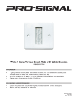
Figure 1: Typical SSL/CSL Series Hopper Loader
• 10” Clearance Cutout with (6) ¼” bolt
holes equally spaced on an 11”
circle.
We are committed to a continuing program of product improvement.
Specifications, appearances, and dimensions are subject to change without notice.
SSL/CSL03 Hopper Loader
A

14
Figure 3:
SSL/CSL Series Dimensions, Specifications, and Maximum Machine-Side Throughput
American Standards
Capacity Dimensions in inches
cu. ft. A B C D E F
0.1
7.0
17
3
/8” 6
3
/8”
12”
1
3
/4” 6
3
/8”
0.2
21
1
/8” 5
1
/2”
12” 4”
9
1
/8”
0.4
27
1
/8” 11
1
/2”
12” 4”
9
1
/8”
0.8 30 ¼” 10 ½” 12” 4”
14
1
/8”
1.6
5.75
36 ½” 17 ¾” 12” 4”
14
1
/8”
Metric Standards
Capacity Dimensions in cm
liters A B C D E F
2.8 17.8 44.1 16.2 30.5 4.4 16.2
5.6 53.7 14.0 30.5 10.1 23.2
11.3 68.9 29.2 30.5 10.1 23.2
22 77 27 12 10.1 36
45
14.6
93 45 12 10.1 36
c
5
/16”/0.313” (8.0 mm) -diameter holes; two (2) places equally spaced.
d
5
/16”/0.313” (8.0 mm) -diameter holes; four (4) places equally spaced.
e
1
/4”/0.250” (6.3 mm) -diameter holes; six (6) places equally spaced;
J is standard mounting hole pattern.
SSL/CSL Series Specifications
Model Hopper capacity Full-load amps Inlet size range Shipping weight
no. cu. ft. liters lbs. Kg (FLA) inches
mm
lbs. Kg
SSL/CSL03 0.1 2.8 3.5 1.5 11 1½”
38 mm
47
22
SSL/CSL06 0.2 5.6 7.0 3.1 11 1½”
38 mm
65
30
SSL/CSL11 0.4 11.3 14.0 6.3 11 1½”
38 mm
67
31
SSL/CSL23 0.8 22 28 12.7 10 1 ½”
38 mm
75
34
SSL/CSL45 1.6 45 56 25.4 10 1 ½”
38 mm
80
36
SSL/CSL Series Maximum Machine-Side Throughput
Twelve (12) -foot (3.66 m) vertical 1½” OD (approx. 38 mm) flex hose; pellets @ 35 lbs./cu. ft. (560 Kg/cu. m)
Model Non-Proportioning c Proportioning
number lbs./hr. Kg/hr. lbs./hr. Kg/hr.
SSL/CSL03 150 68
Not available
SSL/CSL06 500 227 400 182
SSL/CSL11 1,000 454 800 364
SSL/CSL23 1,500 680 1,200 544
SSL/CSL45 1,700 771 1,350 612
c Maximum throughput beside-the-press loading; includes 12-foot (3.6 m) vertical lift.
We are committed to a continuing program of product improvement. Specifications, appearances, and dimensions are subject to
change without notice.

15
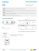
Figure 4: Typical SSIL/CSIL Series Sight Glass Hopper Loader
We are committed to a continuing program of product improvement.
Specifications, appearances, and dimensions are subject to change without notice.
SSIL/CSIL03 Sight Glass
Hopper Loader
SRIL01.DWG
A
B
C
D
E
HOPSRIL.DWG
I
H
E
G
J
SSIL 06 Model

16
Figure 5:
SSIL/CSIL Series Dimensions, Specifications, and Maximum Machine-Side Throughput
American Standards
Capacity Dimensions in inches
cu. ft. A B C D E -sq. G -sq. H -sq. I -sq. c J
0.1
27
5
/8”
17” 6
3
/8” 1
3
/4” 4” 2” 1
1
/4” 2
1
/2” 2”
0.2 35
1
/4” 19
1
/2” 9
1
/8” 3” 7” 3
1
/2” 2
3
/4” 5
1
/2” 3”
0.4 41
1
/4” 25
3
/4” 9
1
/8” 3” 7” 3
1
/2” 2
3
/4” 5
1
/2” 3”
Metric Standards
Capacity Dimensions in cm
liters A B C D E -sq. G -sq. H -sq. I -sq. c J
2.8 74.0 41.9 16.2 4.4 10.2 5.1 3.2 6.3 5.1
5.6 89.5 49.5 23.2 7.6 17.8 8.9 7.0 14.0 7.6
11.3 104.8 65.4 23.2 7.6 17.8 8.9 7.0 14.0 7.6
c 0.281” (7.1 mm) -diameter holes; four (4) places equally spaced.
SSIL/CSIL Series Specifications
Full- Specifications
Selection load Inlet/outlet Square mounting Shipping
Hopper capacity Sight glass capacity Model amps range flange dimensions weight
cu. ft.
liters
lbs.
Kg
cu. ft.
liters
lbs.
Kg
no. FLA inches
mm
inches
mm
lbs.
Kg
0.1
2.8
3.5
1.5
0.02
0.57
0.68
0.31
SSIL/
CSIL03
11 1½”
38 mm
4”
101.6
50
23
0.2
5.6
7.0
3.1
0.09
2.55
3.25
1.48
SSIL/
CSIL06
11 1½”
38 mm
7”
177.8
70
32
0.4
11.3
14.0
6.3
0.09
2.55
3.25
1.48
SSIL/
CSIL11
11 1½”
38 mm
7”
177.8
72
33
SSIL/CSIL Series Maximum Machine-Side Throughput
Twelve (12) -foot (3.66 m) vertical 1½” OD (approx. 38 mm) flex hose; pellets @ 35 lbs./cu. ft. (560 Kg/cu. m)
Model Non-Proportioning c Proportioning
number lbs./hr. Kg/hr. lbs./hr. Kg/hr.
SSIL/CSIL03 150 68
Not available
SSIL/CSIL06 500 227 400 182
SSIL/CSIL11 1,000 454 800 364
c Maximum throughput beside-the-press loading; includes 12-foot (3.6 m) vertical lift.
We are committed to a continuing program of product improvement.
Specifications, appearances, and dimensions are subject to change without notice.

17
Chapter 3: Installation
3-1 Work Rules
Install, operate, and maintain this equipment according to all applicable work and safety codes.
This includes, but is not limited to: OSHA, NEC, CSA, and any other local, national, and
international regulations. Obey these specific work rules:
; Read and follow these instructions when installing, operating and
maintaining this equipment. If the instructions become lost or
unreadable, obtain a new copy from the manufacturer.
; Only qualified persons should work on or with this equipment.
; Work only with approved tools and devices.
; Disconnect and lock out electric power before maintaining or
servicing a hopper loader. If the unit is installed with a power cord
that can be unplugged, unplug it. If the unit is permanently wired to a
power main, have a fused power disconnect, capable of being locked
in the OFF position, installed.
3-2 Safety Considerations
; Connect the hopper loader to a grounded three-prong power
receptacle. If this is not possible, ground the hopper loader motor for
electrical isolation and protection from electric shock.
; Do not use hopper loaders in explosive atmospheres.
; Do not use outdoors or in wet environments. Moisture damages the
motor and can create an electric shock hazard.
; Operate hopper loaders at the rated voltage. Operation at other than
design voltage can result in, at best, poor performance, and can cause
damage to the vacuum motor, control, and personnel.
3-3 Necessary Tools
; Hand drill
; Pop-rivet gun
;
3
/16” (about 4.8 mm) -diameter rivets
3-4 Mounting SSL/CSL and SSIL/CSIL Hopper Loaders
You can mount your SSL/CSL or SSIL/CSIL hopper loader directly to the processing machine
by cutting a hole in the machine bin lid and fastening the hopper loader to it. The hopper
loader mounting flange mates with the equipment and uses the same mounting holes as
previous models.

18
For new installations or mounting on other manufacturer’s equipment, a hole location template
is included in the information packet.
Important!
We are not responsible for equipment damage
from excessive processing machine vibrations.
3-5 Mounting Tips
• Run a bead of silicone sealant around the mounting flange before
seating the hopper loader. This provides an additional seal.
• Use rivets to mount the hopper loader. Bolts, nuts, and washers can
loosen, fall into, and damage process equipment.
• Check across the mounting flange with a bubble level. Level
installation ensures proper material discharge valve operation.
• Install controller boxes to a non-moving solid structure to avoid
loosening any wiring from vibration.
• Remove all rubber banding and any other packaging materials from
around the flapper dump valve before installation for proper
operation.
3-6 Attaching the Pickup Wand
Slide the flex hose onto the material inlet and pickup wand. Use the hose clamps supplied to
secure the flex hose. The flex hose should not cover the aeration holes on the pickup wand.
The pickup wand needs no adjustment for most applications. Insert it into the material to be
conveyed and it will work.
Some applications require a more defined air-to-material ratio. Cover one or more of the holes
at the top of the pickup wand.
3-7 Making Compressed Air Connections
Your SSL/CSL or SSIL/CSIL hopper loader requires a clean, dry, 80 to 120 psi (551.6 to
827.4 kPa/5.52 to 8.27 bars) compressed air supply. A filter, regulator, and shutoff valve are
recommended components of your in-plant compressed air supply.
You may need to install an accumulator in your air supply system to enhance blowback
effectiveness if your system cannot consistently meet these requirements. Make sure you use
full-sized
3
/8”-diameter pipe or tubing when making connections.
3-8 Making Electrical Connections
The controller you selected is shipped pre-wired to the SSL/CSL or SSIL/CSIL Series hopper
loader. Units are supplied with a power cord with plug wired to the control unit, ready to plug
into an appropriately grounded three-prong receptacle.

19
Make sure that the material demand sensor is installed with the proper amount of clearance,
and that it is free of obstructions.
If the installation has the SSL/CSL or SSIL/CSIL Series hopper loader wired directly to a
power main, you must install a fused disconnect with lockout to allow safe operation and
maintenance. Make sure all connections are tight.
3-9 Installing the Remote Control Box
Optional-Series One Plus Controller Only
The remote option permits mounting a control up to 9 feet
(2.75 m) from the primary control box. Both controls remain operational.
! WARNING
HAZARDOUS ELECTRICAL CURRENT
PRESENT.
To avoid burn or electrocution hazard,
disconnect electrical power before
installing this option!
1. Install the SSL/CSL or SSIL/CSIL Series hopper loader.
2. Select a location for the remote box and mount it securely.
3. Plug the cable supplied into the 25-pin receptacle on the hopper
loader controller. Route the cable to the remote box so it doesn’t
interfere with processing operations. Observe all applicable
electrical codes.
4. Connect the cable to the receptacle on the remote control
enclosure.
Both controls are now fully operational.
• Main power supervision is available on the hopper-mounted
control only.
3-10 Adjusting the Proximity Switch
SSIL/CSIL Series Sight Glass Loaders with Series One Plus Controllers Only
The proximity switch, mounted through the side of the hopper loader tank, senses when the
hopper loader is full. It is factory-set to sense most conveyed materials accurately, and

20
provides volume-fill control. When the hopper loader is full, the LED on the proximity switch
should light and trigger the dump sequence.
If the switch does not reliably sense the material you are conveying, adjust switch sensitivity.
Turn the potentiometer (or pot) clockwise to increase sensitivity, counterclockwise to decrease
sensitivity.
Page is loading ...
Page is loading ...
Page is loading ...
Page is loading ...
Page is loading ...
Page is loading ...
Page is loading ...
Page is loading ...
Page is loading ...
Page is loading ...
Page is loading ...
Page is loading ...
Page is loading ...
Page is loading ...
Page is loading ...
Page is loading ...
Page is loading ...
Page is loading ...
Page is loading ...
Page is loading ...
Page is loading ...
Page is loading ...
Page is loading ...
Page is loading ...
Page is loading ...
Page is loading ...
Page is loading ...
Page is loading ...
Page is loading ...
Page is loading ...
Page is loading ...
Page is loading ...
Page is loading ...
Page is loading ...
Page is loading ...
Page is loading ...
Page is loading ...
Page is loading ...
Page is loading ...
Page is loading ...
Page is loading ...
Page is loading ...
Page is loading ...
Page is loading ...
Page is loading ...
Page is loading ...
-
 1
1
-
 2
2
-
 3
3
-
 4
4
-
 5
5
-
 6
6
-
 7
7
-
 8
8
-
 9
9
-
 10
10
-
 11
11
-
 12
12
-
 13
13
-
 14
14
-
 15
15
-
 16
16
-
 17
17
-
 18
18
-
 19
19
-
 20
20
-
 21
21
-
 22
22
-
 23
23
-
 24
24
-
 25
25
-
 26
26
-
 27
27
-
 28
28
-
 29
29
-
 30
30
-
 31
31
-
 32
32
-
 33
33
-
 34
34
-
 35
35
-
 36
36
-
 37
37
-
 38
38
-
 39
39
-
 40
40
-
 41
41
-
 42
42
-
 43
43
-
 44
44
-
 45
45
-
 46
46
-
 47
47
-
 48
48
-
 49
49
-
 50
50
-
 51
51
-
 52
52
-
 53
53
-
 54
54
-
 55
55
-
 56
56
-
 57
57
-
 58
58
-
 59
59
-
 60
60
-
 61
61
-
 62
62
-
 63
63
-
 64
64
-
 65
65
-
 66
66


Sterling SSL User manual
- Type
- User manual
- This manual is also suitable for
Ask a question and I''ll find the answer in the document
Finding information in a document is now easier with AI
Related papers
-
Sterling SSIL Series User manual
-
-
-
-
-
-
-
-
-
Other documents
-
Z.Vex Fuzzolo User manual
-
 PRO SIGNAL PSG03774 Operating instructions
-
 Columbia Lighting COL-CSL8-8040 CSL Striplight User manual
-
HQ W7-60561N Datasheet
-
 Wyndham Collection WCG242460SGGWCUNSMXX Installation guide
-
 ACS Marine Sanitation System XFC-S User manual
-
 PROSOCOUSTIC WR-Pair-SmallPanel-BK User manual
-
Manitou 2003 Swinger Owner's manual
-
Interlogix B4Z-802A-SHOCK User manual
-
LG WT7200CW Owner's manual


