ATEN CCS-SPK-SB-100-B User guide
- Category
- Network switches
- Type
- User guide
This manual is also suitable for
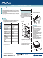
ATEN CCS-SPK-SB-100-B is a high-quality soundbar speaker perfect for use in conference rooms, huddle rooms, and other small to medium-sized spaces. With its sleek design and powerful sound, the CCS-SPK-SB-100-B is the perfect way to enhance your audio experience. Here are some of the key features and possible use cases of the ATEN CCS-SPK-SB-100-B:
- Clear and powerful sound: The CCS-SPK-SB-100-B delivers crystal-clear audio with deep bass, making it perfect for use in conference rooms and other spaces where clear communication is essential.


-
 1
1
-
 2
2
-
 3
3
-
 4
4


ATEN CCS-SPK-SB-100-B User guide
- Category
- Network switches
- Type
- User guide
- This manual is also suitable for
ATEN CCS-SPK-SB-100-B is a high-quality soundbar speaker perfect for use in conference rooms, huddle rooms, and other small to medium-sized spaces. With its sleek design and powerful sound, the CCS-SPK-SB-100-B is the perfect way to enhance your audio experience. Here are some of the key features and possible use cases of the ATEN CCS-SPK-SB-100-B:
- Clear and powerful sound: The CCS-SPK-SB-100-B delivers crystal-clear audio with deep bass, making it perfect for use in conference rooms and other spaces where clear communication is essential.
Ask a question and I''ll find the answer in the document
Finding information in a document is now easier with AI
Related papers
Other documents
-
HUANUO Keyboard Tray Under Desk Installation guide
-
Crestron UC-CAM-WMK Product information
-
-
-
Nextwindow 2700 OverlayTouch 46" User manual
-
-
-
-
-