
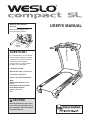
USER'S MANUAL
Serial
Number
Decal
Model No. WETL30708.0
Serial No.
CAUTION
Read all precautions and instruc-
tions in this manual before using
this equipment. Save this manual
for future reference.
QUESTIONS?
As a manufacturer, we are commit-
ted to providing complete customer
satisfaction. If you have questions,
or if there are missing parts,
please contact us at the numbers
or addresses listed below:
Call: 08457 089 009
Outside UK: 0 (44) 113 3877133
Fax: 0 (44) 113 3877125
E-mail: [email protected]
Write:
ICON Health & Fitness, Ltd.
Unit 4
Revie Road Industrial Estate
Revie Road, Beeston
Leeds, LS11 8JG
UK
Write the serial number in the
space above for reference.

2
WESLO is a registered trademark of ICON IP, Inc.
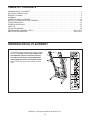
WARNING DECAL PLACEMENT
This drawing shows the location(s) of the warning
decal(s). If a decal is missing or illegible, call
the telephone number on the front cover of
this manual and request a free replacement
decal. Apply the decal in the location shown.
Note: The decal(s) may not be shown at actual
size.
TABLE OF CONTENTS
W
ARNING DECAL PLACEMENT . . . . . . . . . . . . . . . . . . . . . . . . . . . . . . . . . . . . . . . . . . . . . . . . . . . . . . . . . . . . . .2
IMPORTANT PRECAUTIONS . . . . . . . . . . . . . . . . . . . . . . . . . . . . . . . . . . . . . . . . . . . . . . . . . . . . . . . . . . . . . . . . .3
BEFORE YOU BEGIN . . . . . . . . . . . . . . . . . . . . . . . . . . . . . . . . . . . . . . . . . . . . . . . . . . . . . . . . . . . . . . . . . . . . . . .5
ASSEMBLY . . . . . . . . . . . . . . . . . . . . . . . . . . . . . . . . . . . . . . . . . . . . . . . . . . . . . . . . . . . . . . . . . . . . . . . . . . . . . . .6
OPERATION AND ADJUSTMENT . . . . . . . . . . . . . . . . . . . . . . . . . . . . . . . . . . . . . . . . . . . . . . . . . . . . . . . . . . . .15
HOW TO FOLD AND MOVE THE TREADMILL . . . . . . . . . . . . . . . . . . . . . . . . . . . . . . . . . . . . . . . . . . . . . . . . . .20
TROUBLESHOOTING . . . . . . . . . . . . . . . . . . . . . . . . . . . . . . . . . . . . . . . . . . . . . . . . . . . . . . . . . . . . . . . . . . . . . .22
EXERCISE GUIDELINES . . . . . . . . . . . . . . . . . . . . . . . . . . . . . . . . . . . . . . . . . . . . . . . . . . . . . . . . . . . . . . . . . . .25
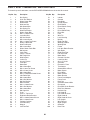
PART LIST . . . . . . . . . . . . . . . . . . . . . . . . . . . . . . . . . . . . . . . . . . . . . . . . . . . . . . . . . . . . . . . . . . . . . . . . . . . . . . .26
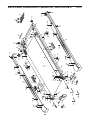
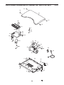
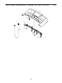
EXPLODED DRAWING . . . . . . . . . . . . . . . . . . . . . . . . . . . . . . . . . . . . . . . . . . . . . . . . . . . . . . . . . . . . . . . . . . . . .28
ORDERING REPLACEMENT PARTS . . . . . . . . . . . . . . . . . . . . . . . . . . . . . . . . . . . . . . . . . . . . . . . . . .Back Cover
RECYCLING INFORMATION . . . . . . . . . . . . . . . . . . . . . . . . . . . . . . . . . . . . . . . . . . . . . . . . . . . . . . . . .Back Cover

1. Before beginning this or any exercise pro-
gram, consult your physician. This is espe-
cially important for persons over age 35 or
persons with pre-existing health problems.
2. It is the responsibility of the owner to ensure
that all users of this treadmill are adequately
informed of all warnings and precautions.
3. Use the treadmill only as described in this
manual.
4. Place the treadmill on a level surface, with at
least 8 ft. (2.4 m) of clearance behind it and
2 ft. (0.6 m) on each side. Do not place the
treadmill on a surface that blocks any air
openings. To protect the floor or carpet from
damage, place a mat under the treadmill.
5. Keep the treadmill indoors, away from mois-
ture and dust. Do not put the treadmill in a
garage or covered patio, or near water.
6. Do not operate the treadmill where aerosol
products are used or where oxygen is being
administered.
7. Keep children under age 12 and pets away
from the treadmill at all times.
8. The treadmill should be used only by per-
sons weighing 265 lbs. (120 kg) or less.
9. Never allow more than one person on the
treadmill at a time.
10. Wear appropriate exercise clothes when
using the treadmill. Do not wear loose
clothes that could become caught in the
treadmill. Athletic support clothes are recom-
mended for both men and women. Always
wear athletic shoes; never use the treadmill
with bare feet, wearing only stockings, or in
sandals.
11. When connecting the power cord (see page
15), plug the power cord into an earthed cir-
cuit. No other appliance should be on the
same circuit. When replacing the fuse, an
ASTA approved BS1362 type should be fitted
to the fuse carrier. A 13 amp fuse should be
used.
12. If an extension cord is needed, use only a 3-
conductor, 14-gauge (1 mm
2
) cord that is no
longer than 5 ft. (1.5 m).
13. Keep the power cord away from heated sur-
faces.
14. Never move the walking belt while the power
is turned off. Do not operate the treadmill if
the power cord or plug is damaged, or if the
treadmill is not working properly. (See TROU-
BLESHOOTING on page 22 if the treadmill is
not working properly.)
15. Read, understand, and test the emergency
stop procedure before using the treadmill (see
HOW TO TURN ON THE POWER on page 17).
16. Never start the treadmill while you are stand-
ing on the walking belt. Always hold the
handrails while using the treadmill.
17. The treadmill is capable of high speeds.
Adjust the speed in small increments to
avoid sudden jumps in speed.
18. Never leave the treadmill unattended while it
is running. Always remove the key, unplug
the power cord, and switch the reset/off cir-
cuit breaker to the off position when the
treadmill is not in use. (See the drawing on
page 5 for the location of the reset/off circuit
breaker.)
19. The pulse sensor is not a medical device.
Various factors, including your movement,
may affect the accuracy of heart rate readings.
The pulse sensor is intended only as an exer-
cise aid in determining heart rate trends in
general.
IMPORTANT PRECAUTIONS
3
WARNING: To reduce the risk of serious injury, read all important precautions and in-
structions in this manual and all warnings on your treadmill before using your treadmill. ICON as-
s
umes no responsibility for personal injury or property damage sustained by or through the use of
this product.

4
20. Do not attempt to raise, lower, or move the
treadmill until it is properly assembled. (See
A
SSEMBLY on page 6, and HOW TO FOLD
AND MOVE THE TREADMILL on page 20.)
You must be able to safely lift 45 lbs. (20 kg)
to raise, lower, or move the treadmill.
21. When folding or moving the treadmill, make
sure that the storage latch is holding the
frame securely in the storage position.
22. Do not change the incline of the treadmill by
placing objects under the treadmill.
23. Inspect and properly tighten all parts of the
treadmill regularly.
24. Never drop or insert any object into any
opening on the treadmill.
25.
DANGER: Always unplug the power
cord immediately after use, before cleaning
the treadmill, and before performing the
m
aintenance and adjustment procedures de-
scribed in this manual. Never remove the
motor hood unless instructed to do so by an
authorized service representative. Servicing
other than the procedures in this manual
should be performed by an authorized ser-
vice representative only.
26. This treadmill is intended for in-home use
only. Do not use this treadmill in any com-
mercial, rental, or institutional setting.
SAVE THESE INSTRUCTIONS

5
Thank you for selecting the new WESLO
®
COMPACT
S
L treadmill. The COMPACT SL treadmill offers a selec-
tion of features designed to make your workouts at
home more effective. And when youʼre not exercising,
the unique treadmill can be folded up, requiring less
t
han half the floor space of other treadmills.
For your benefit, read this manual carefully before
using the treadmill. If you have questions after read-
ing this manual, please see the front cover of this man-
u
al. To help us assist you, please note the product
model number and serial number before contacting us.
The model number and the location of the serial num-
ber decal are shown on the front cover of this manual.
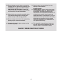
Before reading further, please familiarize yourself with
the parts that are labeled in the drawing below.
BEFORE YOU BEGIN
Handrail
Upright
Key/Clip
Reset/Off
Circuit Breaker
Walking Belt
Platform Cushion
Foot Rail
Idler Roller
Adjustment Bolts
Console
Accessory Tray
Storage Latch
Pulse Sensor
Incline Pin

ASSEMBLY
Assembly requires two persons. Set the treadmill in a cleared area and remove all packing materials; do not
d
ispose of the packing materials until assembly is completed. Note: The underside of the treadmill walking
belt is coated with high-performance lubricant. During shipping, a small amount of lubricant may be transferred to
the top of the walking belt or the shipping carton. This does not affect treadmill performance. If there is lubricant
on top of the walking belt, simply wipe off the lubricant with a soft cloth and a mild, non-abrasive cleaner.
Assembly requires the included hex keys and your own Phillips screwdriver , rubber
mallet , adjustable wrench , and wire cutters .
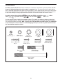
Use the drawings below to identify the assembly hardware. The number in parentheses below each drawing is
the key number of the part, from the PART LIST near the end of this manual. The number after the parentheses
is the quantity needed for assembly. Note: If a part is not in the hardware kit, check to see if it is preattached
to one of the parts to be assembled. To avoid damaging plastic parts, do not use power tools for assem-
bly. Extra hardware may be included.
6
5/16" Star
Washer (2)–6
M10 Star
Washer (8)–2
M4.2 x 19mm
Screw (10)–6
M5 Star
Washer (12)–2
M10 Flat
Washer (16)–4
M8 x 16mm Bolt
(17)–6
M5 x 16mm
Screw (13)–2
M4.2 x 19mm
Tek Screw (14)–4
M10 x 53mm
Patch Bolt (18)–4
M10 x 110mm
Bolt (15)–2
M10 Washer
(4)–2
#10 x 1" Tek Screw
(43)–2

7
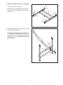
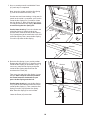
1. Make sure that the power cord is unplugged.
Orient the Base (101) as shown.
Attach four Base Feet (100) to the Base (101) in
t
he locations shown with four M4.2 x 19mm Tek
Screws (14).
1
14
1
00
100
100
100
101
14
14
14
2. Identify the Right Upright (98), which has a large
hole in the location shown.
Orient the Right Upright (98) and the Base (101)
as shown. Attach the Right Upright to the Base
with two M10 x 53mm Patch Bolts (18) and two
M10 Flat Washers (16); do not fully tighten the
Patch Bolts yet.
101
18
16
98
2
Large
Hole

8
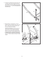
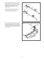
4. With the help of a second person, raise the
Uprights (96, 98) so the Base (101) is flat on the
floor as shown. Next, position the front of the
Frame (67) between the Uprights.
See the inset drawing. Locate the wire tie in-
side the lower end of the Right Upright (98).
Wrap the wire tie around the end of the Wire
Harness (97). Next, locate the opposite end of
the wire tie, which is extending from the top of
the Right Upright. Pull the wire tie until the Wire
Harness is routed completely through the Right
Upright.
97
98
4
Wire
Tie
3
. Orient the Left Upright (96) and the Base (101)
as shown. Attach the Left Upright to the Base
with two M10 x 53mm Patch Bolts (18) and two
M10 Flat Washers (16); do not fully tighten the
P
atch Bolts yet.
96
101
3
18
16
96
101
Wire
Tie
97
98
67
Wire
Tie

9
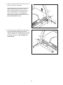
6. Hold the remaining Upright Spacer (54) between
the Left Upright (96) and the Frame (67) as
shown. Attach the Left Upright to the Frame with
an M10 x 110mm (15), an M10 Washer (4), and
an M10 Star Washer (8); do not tighten the
Patch Bolt yet.
6
15
4
54
96
8
67
5. Have a second person raise the Frame (67) and
hold it until step 6 is completed.
H
old an Upright Spacer (54) between the Right
Upright (98) and the Frame (67) as shown.
A
ttach the Right Upright to the Frame with an
M10 x 110mm Bolt (15), an M10 Washer (4),
and an M10 Star Washer (8); do not fully
tighten the Patch Bolt yet. Be careful not to
pinch the Wire Harness (97).
5
67
4
54
8
15
9
8
97

10
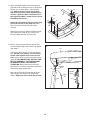
7. Have a second person lift and hold the Frame
(67) until step 8 is completed.
N
ext, place the cylinder end of the Gas Spring
(1) near the bracket on the Base (101).
See the two small inset drawings. Using your fin-
gernail or the end of a screwdriver, press on the
end of the Gas Spring Pin (7) to loosen it from
the Gas Spring (1). Next, rotate the Gas Spring
Pin and pull it out of the Gas Spring. Be careful
to avoid losing the Gas Spring Pin.
See the lower drawing. Press the cylinder end
of the Gas Spring (1) onto the ball on the
bracket. Next, insert the end of the Gas Spring
Pin (7) through two of the small holes in the end
of the Gas Spring. Then, rotate the Gas Spring
Pin until it clips onto the Gas Spring.
1
7
1
7
7
101
67
Bracket
Cylinder
Bracket
7
7
8. Raise the Gas Spring (1) to a vertical position.
Remove the Gas Spring Pin (7) from the raised
end of the Gas Spring as described in step 7. If
necessary, rotate the Gas Spring to align the
end of the Gas Spring with the ball on the
bracket on the Frame (67).
Then, press the end of the Gas Spring (1) onto
the ball. Note: It may be necessary to move
the Frame forward or backwards as you
press the Gas Spring onto the ball.
See the lower drawing. Insert the Gas Spring
Pin (7) into the two indicated small holes in the
end of the Gas Spring (1) Then, rotate the Gas
Spring Pin until it clips onto the Gas Spring.
Note: Extra Gas Spring Pins are included.
Lower the Frame (67) to the floor.
7
1
Holes
7
1
8
67
Bracket
Holes

11
9. Identify the Right Handrail Cover (95) and the
Left Handrail Cover (93). Slide the end of the
Right Handrail (94) through the hole in the Right
H
andrail Cover, and slide the end of Left
Handrail (92) through the hole in the Left
H
andrail Cover.
Attach the Handrail Covers (93, 95) to the
Handrails (92, 94) with two M4.2 x 19mm
Screws (10) in the locations shown.
10
95
Hole
Hole
10
9
3
94
92
9
10. Set the Console (52) face down on a soft sur-
face to avoid scratching the Console. Hold the
Right Handrail (94) near the Console as shown.
Insert the console wire into the large hole on the
side of the Right Handrail and out the hole on
top as shown.
94
10
Large
Hole
52
Console
Wire

12
11. Attach the Right Handrail (94) to the Console
(52) with an M5 x 16mm Screw (13), an M5 Star
Washer (12), and two M4.2 x 19mm Screws
(
10). Make sure that no wires are pinched.
Start all three Screws before tightening any
o
f them. Tighten the M5 x 16mm Screw and
then tighten the M4.2 x 19mm Screws. Do not
overtighten the Screws.
Attach the Left Handrail (92) to the other side
of the Console (52) in the same way. Note:
There are no wires on the left side of the
Console.
Remove the plastic ties from the Right Handrail
(94) and the Left Handrail (92). If necessary,
press the M8 Cage Nuts (41) into place.
11
13
1
3
52
94
92
12
12
10
10
97
12
12. Have a second person hold the Console (52)
near the Right Upright (98) and the Left Upright
(not shown).
Connect the Wire Harness (97) to the console
wire. See the inset drawing. The connectors
should slide together easily and snap into
place. If they do not, turn one connector and try
again. IF THE CONNECTORS ARE NOT CON-
NECTED PROPERLY, THE CONSOLE MAY
BE DAMAGED WHEN THE POWER IS
TURNED ON. Remove the wire tie from the
Wire Harness. Insert the connectors and excess
wire into the Right Upright (98).
Next, set the Console (52) onto the top of the
Right Upright (98) and the Left Upright (not
shown). Make sure that no wires are pinched.
98
97
Console
Wire
52
41
41
Wire
Tie
Console
Wire

13
13. Attach the Console (52) to the Uprights (96, 98)
with six M8 x 16mm Bolts (17) and six 5/16" Star
Washers (2). Start all six Bolts before tighten-
ing any of them.
1
3
2
17
17
17
2
2
2
96
98
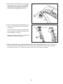
14. With the help of a second person, lower the
Uprights (96, 98) as shown.
See the lower drawing. Position the Uprights
(96, 98) so that the Frame (67) is centered be-
tween the Uprights.
Firmly tighten the M10 x 53mm Patch Bolts (18)
and the M10 x 110mm Bolt (15) on each side of
the treadmill (only one side is shown). Do not
overtighten the M10 x 110mm Bolts.
98
96, 98
15
67
96
View from Above
Side View
14
18
5
2

14
17. Make sure that all parts are properly tightened before you use the treadmill. Note: Extra hardware may
be included. Keep the included hex keys in a secure place; the large hex key is used to adjust the walking
belt (see pages 23 and 24). To protect the floor or carpet, place a mat under the treadmill.
16. Place the treadmill in the storage position (see
HOW TO FOLD AND MOVE THE TREADMILL
on page 20).
Insert the Incline Pins (24) at the desired incline
level (see HOW TO CHANGE THE INCLINE OF
THE TREADMILL on page 19
).
Lower the treadmill (see HOW TO LOWER THE
TREADMILL FOR USE on page 21).
16
24
24
15. Attach the Latch Housing (62) to the Left Upright
(96) with two #10 x 1" Tek Screws (43). Make
sure that the Latch Housing is oriented as
s
hown. Do not overtighten the Screws.
15
62
96
43

15
T
HE PRE-LUBRICATED WALKING BELT
Your treadmill features a walking belt coated with high-performance lubricant. IMPORTANT: Never apply sili-
cone spray or other substances to the walking belt or the walking platform. Such substances will deterio-
r
ate the walking belt and cause excessive wear.
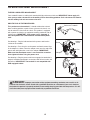
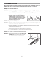
HOW TO PLUG IN THE POWER CORD
This product must be earthed. If it should malfunction or break
down, earthing provides a path of least resistance for electric cur-
rent to reduce the risk of electric shock. This product is equipped
with a power cord having an equipment-earthing conductor and an
earthing plug. IMPORTANT: If the power cord is damaged, it
must be replaced with a manufacturer-recommended power
cord.
See drawing 1. Plug the indicated end of the power cord into the
socket on the treadmill.
See drawing 2. Press the pins on the power cord into the metal clips
in the adapter as shown. Close the adapter cover over the end of the
power cord and tighten the screw in the adapter. IMPORTANT:
Make sure that the adapter cover is secure and the screw has
been tightened before using the power cord.
See drawing 3. Plug the power cord into an appropriate outlet that is
properly installed and earthed in accordance with all local codes and
ordinances. IMPORTANT: The treadmill is not compatible with
RCD-equipped outlets.
OPERATION AND ADJUSTMENT
DANGER: Improper connection of the equipment-earthing conductor can result in an in-
creased risk of electric shock. Check with a qualified electrician or serviceman if you are in doubt as
to whether the product is properly earthed. Do not modify the plug provided with the product—if it will
not fit the outlet, have a proper outlet installed by a qualified electrician.
Socket on Treadmill
Metal
Clips
1
2
Pins
Screw
Adapter
Outlet
3
Adapter
Cover

16
FEATURES OF THE CONSOLE
The treadmill console offers a selection of features
designed to make your workouts more effective. When
you select the manual mode of the console, you can
change the speed of the treadmill with the touch of a
button. As you exercise, the console will display con-
tinuous exercise feedback. You can even measure
your heart rate using the built-in handgrip pulse sensor.
The console also features four speed workouts. Each
workout controls the speed of the treadmill as it guides
you through an effective exercise session.
To turn on the power, see page 17. To use the man-
ual mode of the console, see page 17. To use a
speed workout, see page 19.
IMPORTANT: If there are sheets of clear plastic on
the console, remove the plastic. To prevent damage
to the walking platform, wear clean athletic shoes
while using the treadmill. The first time you use the
treadmill, observe the alignment of the walking
belt, and center the walking belt if necessary (see
page 24).
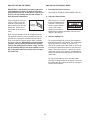
CONSOLE DIAGRAM
Key
Clip

17
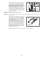
HOW TO TURN ON THE POWER
IMPORTANT: If the treadmill has been exposed to
c
old temperatures, allow it to warm to room tem-
perature before turning on the power. If you do not
d
o this, you may damage the console displays or
other electrical components.
Plug in the power cord (see
page 15). Next, locate the
reset/off circuit breaker on
the treadmill frame near the
power cord. Switch the cir-
cuit breaker to the reset po-
sition.
Next, stand on the foot rails of the treadmill. Find the
clip attached to the key (see the drawing on page 16),
and slide the clip onto the waistband of your clothes.
Then, insert the key into the console. After a moment,
the displays will light. IMPORTANT: In an emergency
situation, the key can be pulled from the console,
causing the walking belt to slow to a stop. Test the
clip by carefully taking a few steps backward; if the
key is not pulled from the console, adjust the posi-
tion of the clip.
HOW TO USE THE MANUAL MODE
1. Insert the key into the console.
See HOW TO TURN ON THE POWER at the left.
2. Select the manual mode.
When the key is inserted,
the manual mode will be
selected. If you have se-
lected a speed workout,
reselect the manual
mode by pressing the
Workout Select button repeatedly until only zeros
appear in the displays.
3. Start the walking belt.
To start the walking belt, press the Start button or
the Digital Speed increase button. The walking belt
will begin to move at 2 km/h. As you exercise,
change the speed of the walking belt as desired by
pressing the Digital Speed increase and decrease
buttons. Each time you press a button, the speed
setting will change by 0.1 km/h; if you hold down a
button, the speed setting will change in increments
of 0.5 km/h.
To stop the walking belt, press the Stop button.
The time will begin to flash in the display. To restart
the walking belt, press the Start button or the Digital
Speed increase button.
Reset
Position

18
4. Follow your progress with the displays.
The lower left
d
isplay—As you exer-
cise, the lower left dis-
p
lay can show the
elapsed time and the
distance that you have
walked or run.
The lower right
display—The lower
right display can show
the speed of the walking
belt and the approxi-
mate number of calories
that you have burned. The display also shows your
heart rate when you use the handgrip pulse sensor
(see step 5).
The upper display—
The upper display can
show the elapsed time,
the distance that you
have walked or run, the
speed of the walking
belt, or the approximate number of calories you
have burned. Press the Display Mode button re-
peatedly until the upper display shows the informa-
tion that you are most interested in viewing. Note:
While information is shown in the upper display, the
same information will not be shown in the lower left
or right display.
To reset the displays, press the Stop button, re-
move the key, and then reinsert the key.
Note: The console can
display speed and dis-
tance in either kilome-
ters or miles. To see
which unit of measure-
ment is selected, remove the key, insert the key
into the console while holding down the Stop but-
ton, and then release the Stop button. An “M” for
m
etric kilometers or an “E” for English miles will ap-
pear in the upper display. Press the Digital Speed
i
ncrease button to change the unit of measurement
if desired. When the desired unit of measurement is
selected, remove the key and then reinsert it.
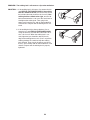
5. Measure your heart rate if desired.
Before using the hand-
grip pulse sensor, re-
move the sheets of clear
plastic from the metal
contacts. In addition,
make sure that your
hands are clean.
To measure your heart rate, stand on the foot
rails and hold the metal contacts—avoid moving
your hands. When your pulse is detected, the small
heart symbol in the lower right display will flash,
one or two dashes will appear, and then your heart
rate will be shown. For the most accurate heart
rate reading, continue to hold the contacts for
about 15 seconds.
6. When you are finished exercising, remove the
key from the console.
Step onto the foot rails, press the Stop button, re-
move the key from the console, and put it in a secure
place.
When you are finished using the treadmill, switch
the reset/off circuit breaker to the “off” position and
unplug the power cord. IMPORTANT: If you do
not do this, the treadmillʼs electrical compo-
nents may wear prematurely.
Metal
Contacts

19
HOW TO USE A SPEED WORKOUT
1. Insert the key into the console.
See HOW TO TURN ON THE POWER on page
1
7.
2. Select one of the four speed workouts.
To select a speed work-
out, press the Workout
Select button repeatedly
until the number of the
desired workout appears
in the upper display. The
maximum speed setting of the selected workout
will appear in the lower right display.
Each workout is divided into 30 one-minute seg-
ments. One speed setting is programmed for each
segment. Note: The same speed setting may be
programmed for consecutive segments.
3. Press the Start button or the Digital Speed in-
crease button to start the workout.
A moment after you press the button, the treadmill
will automatically adjust to the first speed setting of
the workout. Hold the handrails and begin walking.
At the end of each segment of the workout, a se-
ries of tones will sound. In addition, if a different
speed setting is programmed for the next segment,
the speed setting will flash in the display to alert
you. When the next segment begins, the speed of
the walking belt will automatically adjust to the
speed setting for the next segment.
The workout will continue in this way until you have
walked or run for 30 minutes. The walking belt will
then slow to a stop.
If the speed setting for the current segment is too
high or too low, you can override the setting by
pressing the Digital Speed buttons; however,
when the next segment begins, the treadmill
will automatically adjust to the speed setting
for the next segment.
To stop the workout temporarily, press the Stop
button. The time will begin to flash in the display.
To restart the workout, press the Start button or the
D
igital Speed increase button. The walking belt will
begin to move at 2 km/h. When the next segment of
t
he workout begins, the treadmill will automatically
adjust to the speed setting for the next segment.
4. Follow your progress with the displays.
See step 4 on page 18.
5. Measure your heart rate if desired.
See step 5 on page 18.
6. When you are finished exercising, remove the
key from the console.
See step 6 on page 18.
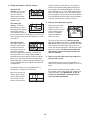
HOW TO CHANGE THE INCLINE OF THE TREADMILL
To vary the intensity of your exercise, you can change
the incline of the treadmill. There are three incline lev-
els. Before changing the incline, remove the key
and unplug the power cord. Next, fold the treadmill
to the storage position (see page 20).
To change the incline, first remove the incline pin from
one of the incline legs. Adjust the incline leg to the de-
sired position, and then fully reinsert the incline pin.
Adjust the other incline leg in the same way. CAUTION:
Before using the treadmill, make sure that both in-
cline legs are at the same height and that both in-
cline pins are fully inserted into the incline legs.
After you have adjusted the incline legs, lower the
treadmill (see page 21).
Incline
Leg
Incline
Pin
Incline
Pin

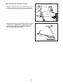
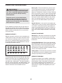
HOW TO FOLD AND MOVE THE TREADMILL
HOW TO FOLD THE TREADMILL FOR STORAGE
Remove the key and unplug the power cord. CAUTION:
Y
ou must be able to safely lift 45 lbs. (20 kg) to raise,
lower, or move the treadmill.
1. Hold the metal frame firmly in the location shown by
the arrow at the right. CAUTION: To decrease the pos-
sibility of injury, do not lift the frame by the plastic
foot rails. Make sure to bend your legs and keep your
back straight as you raise the frame. Raise the frame
about halfway to the vertical position.
2. Move your right hand to the position shown and hold the
treadmill firmly. Using your left hand, pull the latch knob
to the left and hold it. Raise the frame until the hole in the
latch plate is aligned with the latch pin. Slowly release
the latch knob; make sure that the latch pin is fully in-
serted into the latch plate.
To protect the floor or carpet from damage, place a
mat under the treadmill. Keep the treadmill out of di-
rect sunlight. Do not leave the treadmill in the stor-
age position in temperatures above 85° F (30° C).
HOW TO MOVE THE TREADMILL
Before moving the treadmill, convert the treadmill to the
storage position as described above. Make sure that the
latch pin is fully inserted into the latch plate.
1. Hold one handrail and place one foot against one of the
wheels.
2. Tilt the treadmill back until it rolls freely on the wheels.
Carefully move the treadmill to the desired location. To
reduce the risk of injury, use extreme caution while
moving the treadmill. Do not move the treadmill over
an uneven surface.
3. Place a foot against one of the wheels, and carefully
lower the treadmill until it is resting in the storage posi-
tion.
20
Frame
Frame
Handrail
Wheel
Latch Pin
Latch Knob
Latch
Plate
Page is loading ...
Page is loading ...
Page is loading ...
Page is loading ...
Page is loading ...
Page is loading ...
Page is loading ...
Page is loading ...
Page is loading ...
Page is loading ...
Page is loading ...
Page is loading ...
-
 1
1
-
 2
2
-
 3
3
-
 4
4
-
 5
5
-
 6
6
-
 7
7
-
 8
8
-
 9
9
-
 10
10
-
 11
11
-
 12
12
-
 13
13
-
 14
14
-
 15
15
-
 16
16
-
 17
17
-
 18
18
-
 19
19
-
 20
20
-
 21
21
-
 22
22
-
 23
23
-
 24
24
-
 25
25
-
 26
26
-
 27
27
-
 28
28
-
 29
29
-
 30
30
-
 31
31
-
 32
32


Ask a question and I''ll find the answer in the document
Finding information in a document is now easier with AI
Related papers
-
Weslo WETL34709.0 User manual
-
Weslo WETL49713 User manual
-
-
-
-
-
-
Weslo WETL25905 User manual
-
-
Cadence Cadence G 7.0 WLTL39810.0 User manual
Other documents
-
ProForm PETL40807 Owner's manual
-
-
ProForm Style 6500 User manual
-
-
-
-
-
-
-