Page is loading ...

To reduce the impacts on global warming, the packaging materials of this product
are recyclable and reusable. GIGABYTE works with you to protect the environment.
For more product details, please visit GIGABYTE's website.
GA-AX370-Gaming 5
User's Manual
Rev. 1002
12ME-AX37GM5-1002R

Copyright
© 2017 GIGA-BYTE TECHNOLOGY CO., LTD. All rights reserved.
The trademarks mentioned in this manual are legally registered to their respective owners.
Disclaimer
Information in this manual is protected by copyright laws and is the property of GIGABYTE.
Changes to the specications and features in this manual may be made by GIGABYTE without prior notice.
No part of this manual may be reproduced, copied, translated, transmitted, or published in any form or
by any means without GIGABYTE's prior written permission.
For quick set-up of the product, read the Quick Installation Guide included with the product.
In order to assist in the use of this product, carefully read the User's Manual.
For product-related information, check on our website at: http://www.gigabyte.com
Identifying Your Motherboard Revision
The revision number on your motherboard looks like this: "REV: X.X." For example, "REV: 1.0" means
the revision of the motherboard is 1.0. Check your motherboard revision before updating motherboard
BIOS, drivers, or when looking for technical information.
Example:
Motherboard
GA-AX370-Gaming 5
Jan. 23, 2017
Jan. 23, 2017
Motherboard
GA-AX370-Gaming 5

- 3 -
Table of Contents
GA-AX370-Gaming 5 Motherboard Layout .....................................................................4
Chapter 1 Hardware Installation .....................................................................................5
1-1 Installation Precautions .................................................................................... 5
1-2 ProductSpecications ...................................................................................... 6
1-3 Installing the CPU ............................................................................................ 9
1-4 Installing the Memory ....................................................................................... 9
1-5 Installing an Expansion Card ......................................................................... 10
1-6 Back Panel Connectors .................................................................................. 10
1-7 Onboard Buttons, Switches and LEDs ........................................................... 12
1-8 Internal Connectors ........................................................................................ 13
Chapter 2 BIOS Setup ..................................................................................................22
2-1 Startup Screen ............................................................................................... 22
2-2 M.I.T. .............................................................................................................. 23
2-3 System ........................................................................................................... 27
2-4 BIOS ............................................................................................................... 28
2-5 Peripherals ..................................................................................................... 31
2-6 Chipset ........................................................................................................... 33
2-7 Power ............................................................................................................. 34
2-8 Save & Exit ..................................................................................................... 36
Chapter 3 Appendix ......................................................................................................37
3-1 ConguringaRAIDSet .................................................................................. 37
3-2 Drivers Installation .......................................................................................... 39
3-3 Debug LED Codes ......................................................................................... 40
RegulatoryStatements .............................................................................................. 44
Contact Us ................................................................................................................ 48

(Note) For debug code information, please refer to Chapter 3.
- 4 -
GA-AX370-Gaming 5 Motherboard Layout
Box Contents
5 GA-AX370-Gaming 5 motherboard 5 I/O Shield
5 Motherboard driver disk 5 One GC-SLI2P bridge connector
5 User's Manual 5 OneRGB(RGBW)LEDstripextensioncable
5 Quick Installation Guide 5 One G Connector
5 Four SATA cables 5 Two thermistor cables
5 Two Velcro Cable Ties
Socket AM4
KB_MS_USB30
CPU_FAN
SYS_FAN1
ATX
AUDIO
BAT
ATX_12V
CODEC
CLR_CMOS
M_BIOS
PCIEX16
PCIEX1_2
iTE
®
Super I/O
GA-AX370-Gaming 5
F_PANEL
F_USB1F_AUDIO
SPDIF_O
PCIEX1_1
USB30_LAN2
AMD X370
F_USB2
TPM
BIOS_SW
LED_C1
R_USB30
HDMI
TYPEC
USB31
USB31_LAN1
CPU_OPT
CMOS_SW
RST_SW
OC
PW_SW
DDR4_2
DDR4_1
DDR4_4
DDR4_3
ASMedia
®
USB 3.1 Gen 2
Controller
Intel
®
GbE LAN
RivetNetworks
Killer
™
E2500 LAN
SYS_FAN2
SYS_FAN5_PUMP
EC_TEMP1
F_USB30_2
F_USB30_1
U2_32G
SATAEXPRESS
SATA3
7 6
5 4
SATA3
2 0
3 1
EC_TEMP2
SYS_FAN6_PUMP
SYS_FAN3
SYS_FAN4
CPU DRAM
VGA BOOT
Debug LED
(Note)
LED_C2
SB
PCIEX8
PCIEX1_3
PCIEX4
CODEC
M2F_32G
80 60 42
110
B_BIOS
BBIOS_LED
MBIOS_LED
* The box contents above are for reference only and the actual items shall depend on the product package you obtain.
The box contents are subject to change without notice.

Chapter 1 Hardware Installation
1-1 Installation Precautions
The motherboard contains numerous delicate electronic circuits and components which can become
damaged as a result of electrostatic discharge (ESD). Prior to installation, carefully read the user's
manual and follow these procedures:
• Prior to installation, make sure the chassis is suitable for the motherboard.
• Prior to installation, do not remove or break motherboard S/N (Serial Number) sticker or
warranty sticker provided by your dealer. These stickers are required for warranty validation.
• Always remove the AC power by unplugging the power cord from the power outlet before
installing or removing the motherboard or other hardware components.
• Whenconnectinghardwarecomponentstotheinternalconnectorsonthemotherboard,make
sure they are connected tightly and securely.
• Whenhandlingthemotherboard,avoidtouchinganymetalleadsorconnectors.
• It is best to wear an electrostatic discharge (ESD) wrist strap when handling electronic
components such as a motherboard, CPU or memory. If you do not have an ESD wrist strap,
keepyourhandsdryandrsttouchametalobjecttoeliminatestaticelectricity.
• Prior to installing the motherboard, please have it on top of an antistatic pad or within an
electrostatic shielding container.
• Before connecting or unplugging the power supply cable from the motherboard, make sure
the power supply has been turned off.
• Before turning on the power, make sure the power supply voltage has been set according to
the local voltage standard.
• Before using the product, please verify that all cables and power connectors of your hardware
components are connected.
• To prevent damage to the motherboard, do not allow screws to come in contact with the
motherboard circuit or its components.
• Make sure there are no leftover screws or metal components placed on the motherboard or
within the computer casing.
• Do not place the computer system on an uneven surface.
• Do not place the computer system in a high-temperature or wet environment.
• Turning on the computer power during the installation process can lead to damage to system
components as well as physical harm to the user.
• If you are uncertain about any installation steps or have a problem related to the use of the
product,pleaseconsultacertiedcomputertechnician.
• If you use an adapter, extension power cable, or power strip, ensure to consult with its installation
and/or grounding instructions.
- 5 -

1-2 ProductSpecications
CPU AM4 Socket:
- AMDRyzen
™
processor
- AMD 7th Generation A-series/Athlon
™
processors
(Go to GIGABYTE's website for the latest CPU support list.)
Chipset AMD X370
Memory 4xDDR4DIMMsocketssupportingupto64GBofsystemmemory
Dual channel memory architecture
SupportforDDR42667
(Note)
/2400/2133MHzmemorymodules
SupportforECCUn-bufferedDIMM1Rx8/2Rx8memorymodules
Supportfornon-ECCUn-bufferedDIMM1Rx8/2Rx8/1Rx16memorymodules
SupportforExtremeMemoryProle(XMP)memorymodules
(Go to GIGABYTE's website for the latest supported memory speeds and memory
modules.)
Onboard
Graphics
Integrated Graphics Processor:
- 1xHDMIport,supportingamaximumresolutionof4096x2160@24Hz
* Support for HDMI 1.4 version.
- Maximum shared memory of 2 GB
Audio 2xRealtek
®
ALC1220 codecs
Support for Sound Blaster X-Fi MB5
HighDenitionAudio
2/4/5.1/7.1-channel
Support for S/PDIF Out
LAN 1 x Intel
®
GbE LAN chip (10/100/1000 Mbit) (LAN1)
1xRivetNetworksKiller
™
E2500 LAN chip (10/100/1000 Mbit) (LAN2)
* Teaming is not supported.
Expansion Slots 1 x PCI Express x16 slot, running at x16 (PCIEX16)
(Note)
* For optimum performance, if only one PCI Express graphics card is to be installed,
be sure to install it in the PCIEX16 slot.
1 x PCI Express x16 slot, running at x8 (PCIEX8)
(Note)
* ThePCIEX8slotsharesbandwidthwiththePCIEX16slot.WhenthePCIEX8slot
is populated, the PCIEX16 slot operates at up to x8 mode.
(The PCIEX16 and PCIEX8 slots conform to PCI Express 3.0 standard.)
1 x PCI Express x16 slot, running at x4 (PCIEX4)
* The PCIEX4 slot shares bandwidth with all of the PCI Express x1 slots. The PCIEX4
slot operates at up to x4 mode when all of the PCI Express x1 slots are empty.
3 x PCI Express x1 slots
* All of the PCI Express x1 slots share bandwidth with the PCIEX4 slot. The PCIEX4/
PCIEX1_2/PCIEX1_3 slot operates at up to x1 mode when the PCIEX1_1 slot is
populated; the PCIEX4 slot operates at up to x2 mode when the PCIEX1_2/PCIEX1_3
slot is populated.
(The PCIEX4 and PCI Express x1 slots conform to PCI Express 2.0 standard.)
Storage Interface Chipset:
- 1 x M.2 connector (Socket 3, M key, type 2242/2260/2280/22110 SATA and
PCIe x4
(Note)
/x2 SSD support)
- 1 x U.2 connector
*WhentheU.2connectorispopulated,theM.2connectorbecomesunavailable.
(Note) Actual support may vary by CPU.
- 6 -
Storage Interface Chipset:
- 2 x SATA Express connectors
- 8 x SATA 6Gb/s connectors
- SupportforRAID0,RAID1,andRAID10
* Referto"1-8InternalConnectors,"fortheinstallationnoticesfortheM.2andSATA
connectors.
Multi-Graphics
Technology
Support for NVIDIA
®
Quad-GPU SLI
™
and2-WayNVIDIA
®
SLI
™
technologies
Support for AMD Quad-GPU CrossFire
™
and2-WayAMDCrossFire
™
technologies
USB ASMedia
®
USB 3.1 Gen 2 Controller:
- 1 x USB Type-C
™
port on the back panel, with USB 3.1 Gen 2 support
- 1 x USB 3.1 Gen 2 Type-A port (red) on the back panel
Chipset:
- 2 x USB 3.1 Gen 2 Type-A ports (red) on the back panel
- 6 x USB 3.1 Gen 1 ports (2 ports on the back panel, 4 ports available through
the internal USB headers)
- 4 x USB 2.0/1.1 ports (available through the internal USB headers)
CPU:
- 4 x USB 3.1 Gen 1 ports on the back panel
Internal
Connectors
1 x 24-pin ATX main power connector
1 x 8-pin ATX 12V power connector
1 x U.2 connector
1 x M.2 Socket 3 connector
2 x SATA Express connectors
8 x SATA 6Gb/s connectors
1 x CPU fan header
1 x water cooling CPU fan header
4 x system fan headers
2 x system fan/water cooling pump headers
1 x front panel header
1 x front panel audio header
1 x S/PDIF Out header
2 x USB 3.1 Gen 1 headers
2 x USB 2.0/1.1 headers
1 x Trusted Platform Module (TPM) header
1xCPUcoolerLEDstrip/RGBLEDstripextensioncableheader
1xRGB(RGBW)LEDstripextensioncableheader
2 x temperature sensor headers
1 x Clear CMOS jumper
1 x power button
1 x reset button
1 x Clear CMOS button
1 x OC button
2 x BIOS switches
Back Panel
Connectors
1 x PS/2 keyboard/mouse port
1 x HDMI port
1 x USB Type-C
™
port, with USB 3.1 Gen 2 support
3 x USB 3.1 Gen 2 Type-A ports (red)
6 x USB 3.1 Gen 1 ports
2xRJ-45ports
1 x optical S/PDIF Out connector
- 7 -

Back Panel
Connectors
5xaudiojacks (Center/Subwoofer Speaker Out, Rear Speaker Out, Line In,
Line Out, Mic In)
I/O Controller iTE
®
I/O Controller Chip
Hardware
Monitor
Voltage detection
Temperature detection
Fan speed detection
Overheating warning
Fan fail warning
Fan speed control
* Whetherthefan(pump)speedcontrolfunctionissupportedwilldependonthefan
(pump) you install.
BIOS 2x128Mbitash
Use of licensed AMI UEFI BIOS
Support for DualBIOS
™
PnP1.0a,DMI2.7,WfM2.0,SMBIOS2.7,ACPI5.0
Unique Features Support for APP Center
* Available applications in APP Center may vary by motherboard model. Supported
functionsofeachapplicationmayalsovarydependingonmotherboardspecications.
- @BIOS
- 3D OSD
- AutoGreen
- BIOS Setup
- Cloud Station
- Color Tempertaure
- EasyTune
- Fast Boot
- Game Boost
- ON/OFF Charge
- RGBFusion
- Smart Backup
- Smart Keyboard
- Smart TimeLock
- System Information Viewer
- USB Blocker
- USB DAC UP 2
- V-Tuner
Support for Q-Flash
Support for Xpress Install
Bundled
Software
Norton
®
Internet Security (OEM version)
Operating
System
SupportforWindows1064-bit
SupportforWindows764-bit
* Pleasedownloadthe"WindowsUSBInstallationTool"fromGIGABYTE'swebsite
andinstallitbeforeinstallingWindows7.
Form Factor ATX Form Factor; 30.5cm x 24.4cm
* GIGABYTEreservestherighttomakeanychangestotheproductspecicationsandproduct-relatedinformationwithout
prior notice.
- 8 -
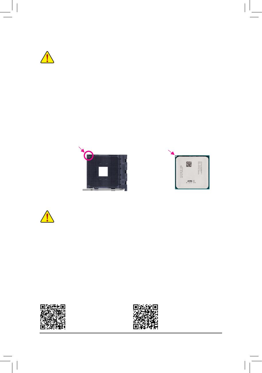
1-3 Installing the CPU
Installing the CPU
Locate the pin one (denoted by a small triangle) of the CPU socket and the CPU.
AM4 Socket
A Small Triangle Marking
Denotes Pin One of the
Socket
AM4 CPU
A Small Triangle Marking
Denotes CPU Pin One
Please visit GIGABYTE's website
for support lists of CPU, memory
modules, SSDs, M.2, and U.2 devices.
Please visit the Support\Utility List
page on GIGABYTE's website to
download the latest version of apps.
1-4 Installing the Memory
DualChannelMemoryConguration
This motherboard provides four memory sockets and supports Dual Channel Technology. After the memory
isinstalled,theBIOSwillautomaticallydetectthespecicationsandcapacityofthememory.EnablingDual
Channel memory mode will double the original memory bandwidth.
The four memory sockets are divided into two channels and each channel has two memory sockets as following:
ChannelA:DDR4_2,DDR4_4
ChannelB:DDR4_1,DDR4_3
Readthefollowingguidelinesbeforeyoubegintoinstallthememory:
• Make sure that the motherboard supports the memory. It is recommended that memory of the
same capacity, brand, speed, and chips be used.
(Go to GIGABYTE's website for the latest supported memory speeds and memory modules.)
• Always turn off the computer and unplug the power cord from the power outlet before installing the
memory to prevent hardware damage.
• Memory modules have a foolproof design. A memory module can be installed in only one direction.
If you are unable to insert the memory, switch the direction.
ReadthefollowingguidelinesbeforeyoubegintoinstalltheCPU:
• Make sure that the motherboard supports the CPU.
(Go to GIGABYTE's website for the latest CPU support list.)
• Always turn off the computer and unplug the power cord from the power outlet before installing the
CPU to prevent hardware damage.
• Locate the pin one of the CPU. The CPU cannot be inserted if oriented incorrectly. (Or you may
locate the notches on both sides of the CPU and alignment keys on the CPU socket.)
• Apply an even and thin layer of thermal grease on the surface of the CPU.
• Do not turn on the computer if the CPU cooler is not installed, otherwise overheating and damage
of the CPU may occur.
• SettheCPUhostfrequencyinaccordancewiththeCPUspecications.Itisnotrecommended
thatthesystembusfrequencybesetbeyondhardwarespecicationssinceitdoesnotmeetthe
standard requirements for the peripherals. If you wish to set the frequency beyond the standard
specications,pleasedosoaccordingtoyourhardwarespecicationsincludingtheCPU,graphics
card, memory, hard drive, etc.
- 9 -
Please visit GIGABYTE's website for details on hardware installation.
1-5 Installing an Expansion Card
Readthefollowingguidelinesbeforeyoubegintoinstallanexpansioncard:
• Make sure the motherboard supports the expansion card. Carefully read the manual that came
with your expansion card.
• Always turn off the computer and unplug the power cord from the power outlet before installing an
expansion card to prevent hardware damage.
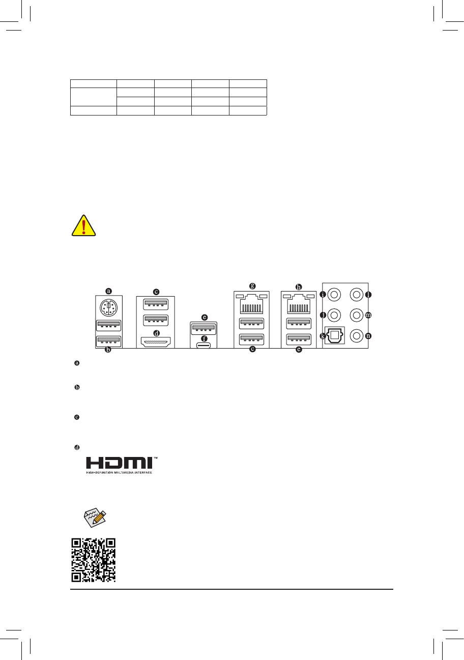
PS/2 Keyboard/Mouse Port
Use this port to connect a PS/2 mouse or keyboard.
USB 3.1 Gen 1 Port
TheUSB3.1Gen1portsupportstheUSB3.1Gen1specicationandiscompatibletotheUSB2.0
specication.YoucanconnectaUSBDACtothisportorusethisportforUSBdevices.
USB 3.1 Gen 1 Port
TheUSB3.1Gen1portsupportstheUSB3.1Gen1specicationandiscompatibletotheUSB2.0
specication.UsethisportforUSBdevices.
HDMI Port
The HDMI port is HDCP compliant and supports Dolby TrueHD and DTS HD
MasterAudio formats.Italsosupports upto192KHz/24bit 8-channelLPCM
audio output. You can use this port to connect your HDMI-supported monitor. The maximum supported
resolutionis4096x2160@24Hz, but theactualresolutionssupportedare dependent onthemonitor
being used.
1-6 Back Panel Connectors
Due to CPU limitations, read the following guidelines before installing the memory in Dual Channel mode.
1. Dual Channel mode cannot be enabled if only one memory module is installed.
2. WhenenablingDualChannelmodewithtwoorfourmemorymodules,itisrecommendedthatmemory
of the same capacity, brand, speed, and chips be used and installed in the same colored sockets. For
optimum performance, when enabling Dual Channel mode with two memory modules, we recommend
thatyouinstallthemintheDDR4_1andDDR4_2sockets.
After installing the HDMI device, make sure to set the default sound playback device to HDMI. (The
item name may differ depending on your operating system.)
DualChannelMemoryCongurationsTable:
DDR4_4 DDR4_2 DDR4_3 DDR4_1
Two Modules
- - DS/SS - - DS/SS
DS/SS - - DS/SS - -
Four Modules DS/SS DS/SS DS/SS DS/SS
(SS=Single-Sided,DS=Double-Sided,"--"=NoMemory)
- 10 -

USB 3.1 Gen 2 Type-A Port (Red)
TheUSB3.1Gen2Type-AportsupportstheUSB3.1Gen2specicationandiscompatibletotheUSB
3.1Gen1andUSB2.0specication.UsethisportforUSBdevices.
USB Type-C
™
Port
ThereversibleUSBportsupportstheUSB3.1Gen2specicationandiscompatibletotheUSB3.1Gen1
andUSB2.0specication.UsethisportforUSBdevices.
RJ-45 LAN Port (LAN2)
The Gigabit Ethernet LAN port provides Internet connection at up to 1 Gbps data rate. The following
describes the states of the LAN port LEDs.
• ToenableorconguretheaudioamplifyingfunctionfortheLineoutjack,pleaseaccesstheHD
Audio Manager application.
• If you want to install a Side Speaker, you need to retask either the Line in or Mic in jack to be Side
Speaker out using the HD Audio Manager application.
• Please visit GIGABYTE's website for more audio software information.
• Whenremovingthecableconnectedtoabackpanelconnector,rstremovethecablefromyour
device and then remove it from the motherboard.
• Whenremovingthecable,pullitstraightoutfromtheconnector.Donotrockitsidetosidetoprevent
an electrical short inside the cable connector.
Activity LED
Connection/
Speed LED
LAN Port
Activity LED:Connection/Speed LED:
State Description
Orange 1 Gbps data rate
Green 100 Mbps data rate
Off 10 Mbps data rate
State Description
Blinking Data transmission or receiving is occurring
Off No data transmission or receiving is occurring
RJ-45 LAN Port (LAN1)
The Gigabit Ethernet LAN port provides Internet connection at up to 1 Gbps data rate. The following
describes the states of the LAN port LEDs.
Activity LED
Connection/
Speed LED
LAN Port
Activity LED:Connection/Speed LED:
State Description
Orange 1 Gbps data rate
Green 100 Mbps data rate
Off 10 Mbps data rate
State Description
Blinking Data transmission or receiving is occurring
On No data transmission or receiving is occurring
Center/Subwoofer Speaker Out
Usethisaudiojacktoconnectcenter/subwooferspeakersina5.1/7.1-channelaudioconguration.
Rear Speaker Out
Thisjackcanbeusedtoconnectrearspeakersina4/5.1/7.1-channelaudioconguration.
Optical S/PDIF Out Connector
This connector provides digital audio out to an external audio system that supports digital optical audio.
Before using this feature, ensure that your audio system provides an optical digital audio in connector.
Line In
The line in jack. Use this audio jack for line in devices such as an optical drive, walkman, etc.
Line Out
The line out jack. This jack supports audio amplifying function. For better sound quality, it is recommended
that you connect your headphone/speaker to this jack (actual effects may vary by the device being used).
Use this audio jack for a headphone or 2-channel speaker. This jack can be used to connect front speakers
ina4/5.1/7.1-channelaudioconguration.
Mic In
The Mic in jack.
- 11 -
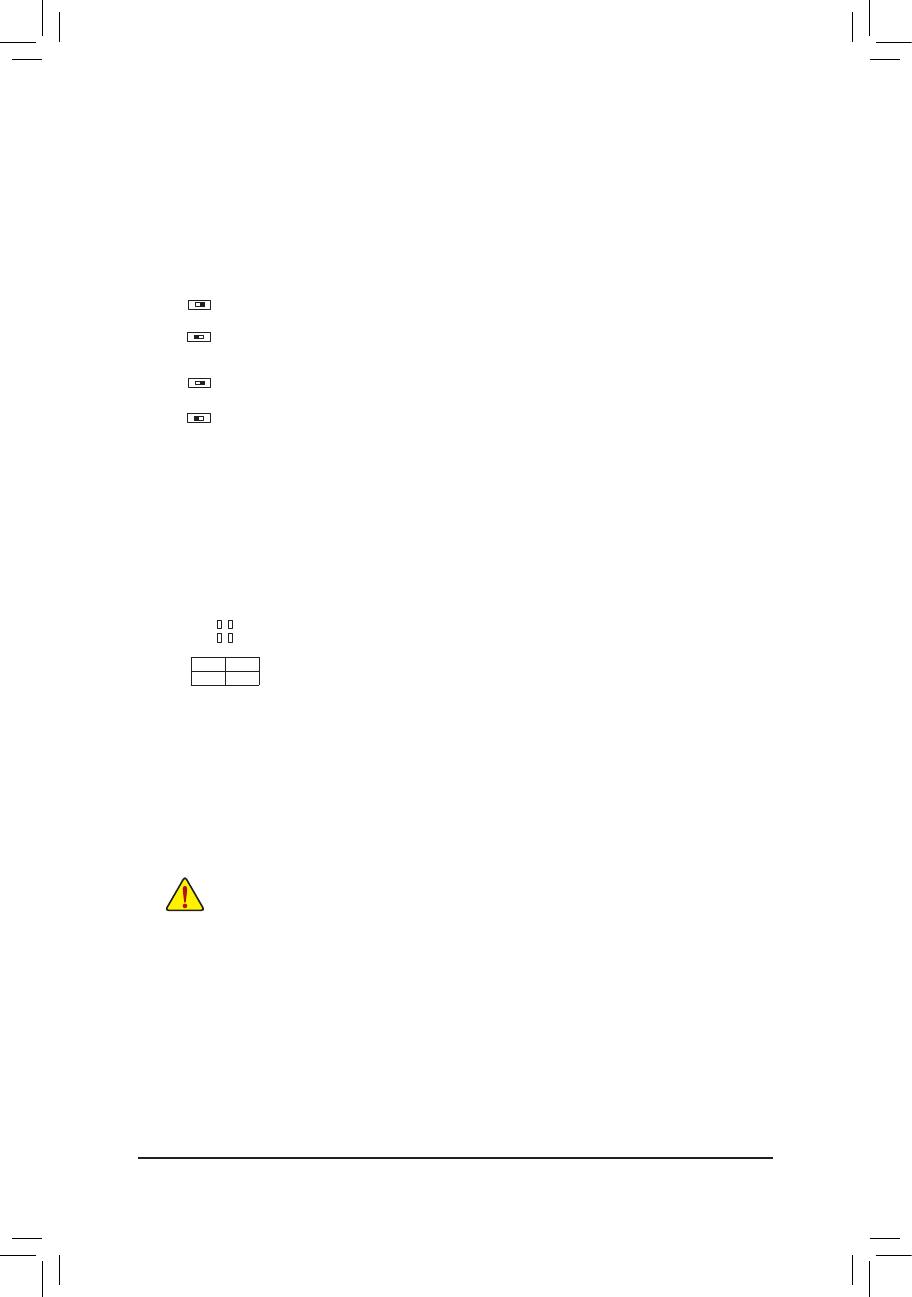
1-7 Onboard Buttons, Switches and LEDs
BIOS Switches and BIOS LED Indicators
TheBIOSswitch(BIOS_SW)allowsuserstoeasilyselectadifferentBIOSforbootuporoverclocking,helping
to reduce BIOS failure during overclocking. The DualBIOS™ (SB) switch allows for enabling or disabling of the
DualBIOS™ function. The LED indicator (MBIOS_LED/BBIOS_LED) shows which BIOS is active.
2: Backup BIOS (Boot from the backup BIOS)
1: Main BIOS (Boot from the main BIOS)
BIOS_SW
2: Single BIOS
1: Dual BIOS
SB
F_USB30
F_U
B_
F_ F_
_
B
BS_
B
SB_
B
_S
S_
_
B
_U
_
B
S
123
123
123
123
1
1
1
1
BSS
S
_S
SSU
1 2 3
S3
BSSS
U
__ 3
F_USB3F
S _
S _
S _
SF
B_
B_
F
_0
S
S
_0F
_F
_
_
__B
U
S _S
_
USB0_B
B_
F_USB3
2 1
F_USB30
F_U
B_
F_ F_
_
B
BS_
B
SB_
B
_S
S_
_
B
_U
_
B
S
123
123
123
123
1
1
1
1
BSS
S
_S
SSU
1 2 3
S3
BSSS
U
__ 3
F_USB3F
S _
S _
S _
SF
B_
B_
F
_0
S
S
_0F
_F
_
_
__B
U
S _S
_
USB0_B
B_
F_USB3
2 1
F_USB30
F_U
B_
F_ F_
_
B
BS_
B
SB_
B
_S
S_
_
B
_U
_
B
S
123
123
123
123
1
1
1
1
BSS
S
_S
SSU
1 2 3
S3
BSSS
U
__ 3
F_USB3F
S _
S _
S _
SF
B_
B_
F
_0
S
S
_0F
_F
_
_
__B
U
S _S
_
USB0_B
B_
F_USB3
2 1
F_USB30
F_U
B_
F_ F_
_
B
BS_
B
SB_
B
_S
S_
_
B
_U
_
B
S
123
123
123
123
1
1
1
1
BSS
S
_S
SSU
1 2 3
S3
BSSS
U
__ 3
F_USB3F
S _
S _
S _
SF
B_
B_
F
_0
S
S
_0F
_F
_
_
__B
U
S _S
_
USB0_B
B_
F_USB3
2 1
MBIOS_LED (The main BIOS is active)
BBIOS_LED (The backup BIOS is active)
BIOS LED Indicators:
CPU/VGA/DRAM/BOOT (Status LEDs)
The status LEDs show whether the CPU, graphics card, memory, and operating system are working properly
aftersystempower-on.IftheCPU/VGA/DRAMLEDison,thatmeansthecorrespondingdeviceisnotworking
normally; if the BOOT LED is on, that means you haven't entered the operating system yet.
CPU: CPU status LED
VGA: Graphics card status LED
DRAM: Memory status LED
BOOT: Operating system status LED
F_USB30
F_U
B_
F_ F_
_
B
BS_
B
SB_
B
_S
S_
_
B
_U
_
B
S
123
123
123
123
1
1
1
1
BSS
S
_S
SSU
1 2 3
S3
BSSS
U
__ 3
F_USB3F
S _
S _
S _
SF
B_
B_
F
_0
S
S
_0F
_F
_
_
__B
U
S _S
_
USB0_B
B_
F_USB3
CPU DRAM
VGA BOOT
Quick Buttons
This motherboard has 3 quick buttons: power button, reset button and clear CMOS button. The power button
and reset button allow users to quickly turn on/off or reset the computer in an open-case environment when
they want to change hardware components or conduct hardware testing.
Use this button to clear the BIOS
congurationandresettheCMOSvaluestofactorydefaultswhenneeded.
PW_SW: Power Button
RST_SW: ResetButton
CMOS_SW: Clear CMOS Button
• Always turn off your computer and unplug the power cord from the power outlet before clearing
the CMOS values.
• NOTE: Do not use the clear CMOS button when the system is on, or the system may shutdown
and data loss or damage may occur.
• Aftersystemrestart,gotoBIOSSetuptoloadfactorydefaults(selectLoadOptimizedDefaults)or
manuallyconguretheBIOSsettings(refertoChapter2,"BIOSSetup,"forBIOScongurations).
OC Button
The OC button helps enthusiasts and overclockers not only get the most performance from their hardware, but
also the absolute most enjoyable OC experience.
OC Button:
PressthisbuttontoloadthemostoptimizedGIGABYTEoverclocking
congurationforyourhardware.
- 12 -

1-8 Internal Connectors
Readthefollowingguidelinesbeforeconnectingexternaldevices:
• First make sure your devices are compliant with the connectors you wish to connect.
• Before installing the devices, be sure to turn off the devices and your computer. Unplug the power
cord from the power outlet to prevent damage to the devices.
• After installing the device and before turning on the computer, make sure the device cable has
been securely attached to the connector on the motherboard.
1
2
3
4 6
16
8
18
15 199
13
20
4
5
4
6
7
7
10
11
11
12
14
17
21
1) ATX_12V
2) ATX
3) CPU_FAN
4) SYS_FAN1/2/3/4
5) CPU_OPT
6) SYS_FAN5_PUMP/SYS_FAN6_PUMP
7) EC_TEMP1/EC_TEMP2
8) LED_C1
9) LED_C2
10) SATA EXPRESS
11) SATA3 0/1/2/3/4/5/6/7
12) U2_32G
13) M2F_32G
14) F_PANEL
15) F_ AUDIO
16) SPDIF_O
17) F_USB30_1/F_USB30_2
18) F_USB1/F_USB2
19) TPM
20) BAT
21) CLR_CMOS
- 13 -
DEBUG
PORT
G.QBOFM
131
24
12
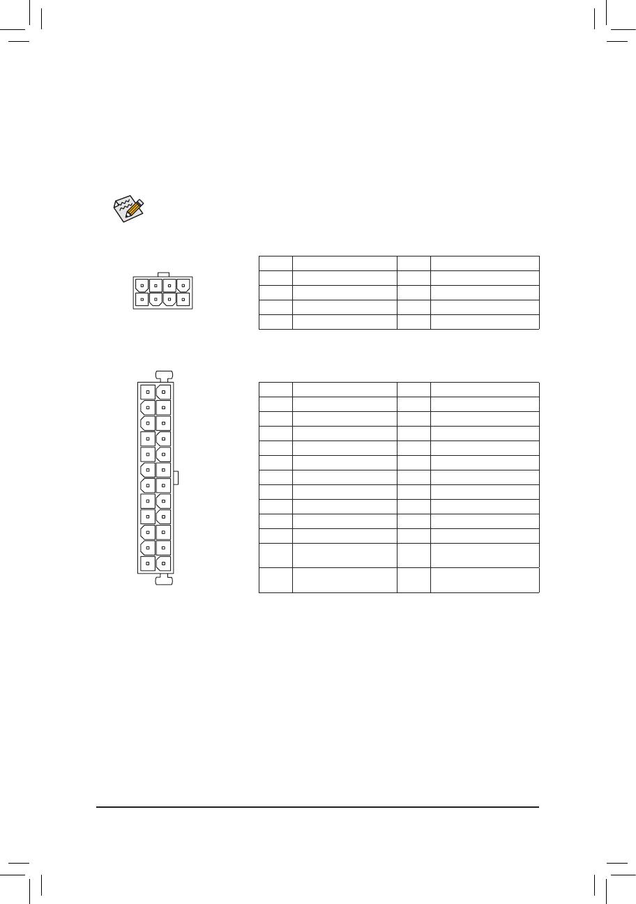
ATX
1/2) ATX_12V/ATX (2x4 12V Power Connector and 2x12 Main Power Connector)
Withtheuseofthepowerconnector,thepowersupplycansupplyenoughstablepowertoallthecomponents
onthemotherboard.Beforeconnectingthepowerconnector,rstmakesurethepowersupplyisturned
off and all devices are properly installed. The power connector possesses a foolproof design. Connect the
power supply cable to the power connector in the correct orientation.
The 12V power connector mainly supplies power to the CPU. If the 12V power connector is not connected,
the computer will not start.
To meet expansion requirements, it is recommended that a power supply that can withstand high
powerconsumptionbeused(500Worgreater).Ifapowersupplyisusedthatdoesnotprovidethe
required power, the result can lead to an unstable or unbootable system.
ATX:
Pin No. Denition Pin No. Denition
1 3.3V 13 3.3V
2 3.3V 14 -12V
3 GND 15 GND
4 +5V 16 PS_ON (soft On/Off)
5 GND 17 GND
6 +5V 18 GND
7 GND 19 GND
8 Power Good 20 NC
9 5VSB (stand by +5V) 21 +5V
10 +12V 22 +5V
11 +12V (Only for 2x12-pin
ATX)
23 +5V (Only for 2x12-pin ATX)
12 3.3V (Only for 2x12-pin
ATX)
24 GND (Only for 2x12-pin ATX)
ATX_12V:
Pin No. Denition Pin No. Denition
1 GND (Only for 2x4-pin 12V) 5 +12V (Only for 2x4-pin 12V)
2 GND (Only for 2x4-pin 12V) 6 +12V (Only for 2x4-pin 12V)
3 GND 7 +12V
4 GND 8 +12V
DEBUG
PORT
G.QBOFM
ATX_12V
8
4
5
1
- 14 -
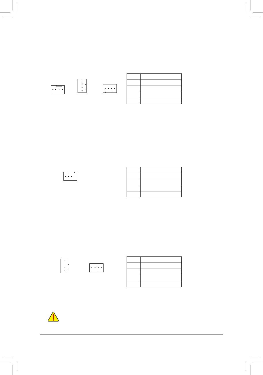
3/4) CPU_FAN/SYS_FAN1/2/3/4 (Fan Headers)
All fan headers on this motherboard are 4-pin. Most fan headers possess a foolproof insertion design.
Whenconnectingafancable,besuretoconnectitinthecorrectorientation(theblackconnectorwireis
the ground wire). The speed control function requires the use of a fan with fan speed control design. For
optimum heat dissipation, it is recommended that a system fan be installed inside the chassis.
CPU_FAN
DEBUG
PORT
G.QBOFM
1
Pin No. Denition
1 GND
2 Voltage Speed Control
3 Sense
4 PWMSpeedControl
DEBUG
PORT
G.QBOFM
DEBUG
PORT
G.QBOFM
1
1
SYS_FAN3/4SYS_FAN1/2
5) CPU_OPT (Water Cooling CPU Fan Header)
The fan header is 4-pin and possesses a foolproof insertion design. Most fan headers possess a foolproof
insertiondesign.Whenconnectingafancable,besuretoconnectitinthecorrectorientation(theblack
connector wire is the ground wire). The speed control function requires the use of a fan with fan speed
control design.
Pin No. Denition
1 GND
2 Voltage Speed Control
3 Sense
4 PWMSpeedControl
DEBUG
PORT
G.QBOFM
1
• Be sure to connect fan cables to the fan headers to prevent your CPU and system from
overheating. Overheating may result in damage to the CPU or the system may hang.
• Thesefanheadersarenotcongurationjumperblocks.Donotplaceajumpercapontheheaders.
DEBUG
PORT
G.QBOFM
1
SYS_FAN5_PUMP
SYS_FAN6_PUMP
6) SYS_FAN5_PUMP/SYS_FAN6_PUMP (System Fan/Water Cooling Pump Headers)
Thefan/pumpheadersare4-pin.Mostfanheaderspossessafoolproofinsertiondesign.Whenconnecting
a fan cable, be sure to connect it in the correct orientation (the black connector wire is the ground wire).
The speed control function requires the use of a fan with fan speed control design. For optimum heat
dissipation, it is recommended that a system fan be installed inside the chassis. The headers also provides
speedcontrolforawatercoolingpump,refertoChapter2,"BIOSSetup,""M.I.T.,"formoreinformation
DEBUG
PORT
G.QBOFM
1
Pin No. Denition
1 GND
2 Voltage Speed Control
3 Sense
4 PWMSpeedControl
- 15 -
7) EC_TEMP1/EC_TEMP2 (Temperature Sensor Headers)
Connect the thermistor cables to the headers for temperature detection.
Pin No. Denition
1 SENSORIN
2 GND
1
1
EC_TEMP1 EC_TEMP2
Pin No. Denition
1 12V
2 G
3 R
4 B
DEBUG
PORT
G.QBOFM
1
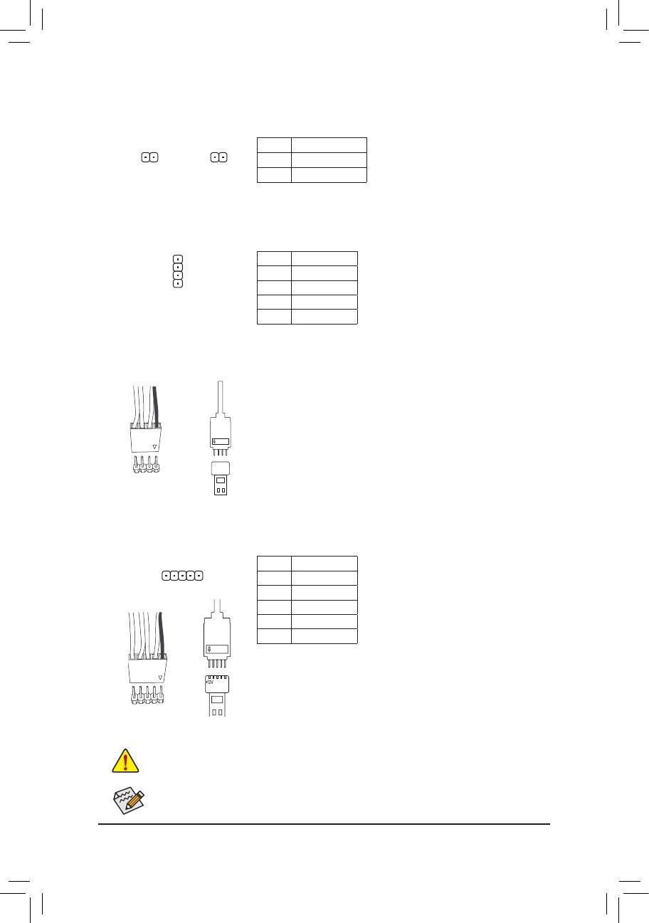
8) LED_C1 (CPU Cooler LED Strip/RGB LED Strip Extension Cable Header)
TheheadercanbeusedtoconnectaCPUcoolerLEDstriporastandard5050RGBLEDstrip(12V/G/R/B),
with maximum power rating of 2A (12V) and maximum length of 2m.
Connecting the CPU cooler LED strip:
Connect the connector of the CPU cooler LED strip (marked with an arrow) to Pin 1 (12V) of this header.
Pin No. Denition
1 12V
2 G
3 R
4 B
5 W
F_USB30
F_U
B_
F_ F_
_
B
BS_
B
SB_
B
_S
S_
_
B
_U
_
B
S
123
123
123
123
1
1
1
1
BSS
S
_S
SSU
1 2 3
S3
BSSS
U
__ 3
F_USB3F
S _
S _
S _
SF
B_
B_
F
_0
S
S
_0F
_F
_
_
__B
U
S _S
_
USB0_B
B_
F_USB3
1
Before installing the devices, be sure to turn off the devices and your computer. Unplug the power
cord from the power outlet to prevent damage to the devices.
9) LED_C2 (RGB (RGBW) LED Strip Extension Cable Header)
Theheadercanbeusedtoconnectastandard5050RGB(RGBW)LEDstrip(12V/G/R/B/W),withmaximum
power rating of 2A (12V) and maximum length of 2m.
ConnectoneendoftheRGB(RGBW)LEDstripextensioncabletothe
headerandtheotherendtoyourRGB(RGBW)LEDstrip.Theblack
wire (marked with a triangle on the plug) of the extension cable must be
connected to Pin 1 (12V) of this header. The 12V pin (marked with an
arrow) on the other end of the extension cable must be lined up with the
12V of the LED strip. Be careful with the connection orientation of the
LED strip; incorrect connection may lead to the damage of the LED strip.
12V
1
Black wire
12V of the
LED strip
Forhowtoturn on/off thelightsoftheRGB (RGBW) LED strip, refertotheinstructionson in
Chapter2,"BIOSSetup."
12V
1
Black wire
12V of the
LED strip
Connecting the standard LED strip:
ConnectoneendoftheRGBLEDstripextensioncabletotheheader
andtheotherendtoyourRGBLEDstrip.Theblackwire(markedwith
a triangle on the plug) of the extension cable must be connected to Pin
1 (12V) of this header. The 12V pin (marked with an arrow) on the other
end of the extension cable must be lined up with the 12V of the LED
strip. Be careful with the connection orientation of the LED strip; incorrect
connection may lead to the damage of the LED strip.
- 16 -
1
1
7 6
5 4
F_USB30
F_U
B_
F_ F_
_
B
BS_
B
SB_
B
_S
S_
_
B
_U
_
B
S
123
123
123
123
1
1
1
1
BSS
S
_S
SSU
1 2 3
S3
BSSS
U
__ 3
F_USB3F
S _
S _
S _
SF
B_
B_
F
_0
S
S
_0F
_F
_
_
__B
U
S _S
_
USB0_B
B_
F_USB3
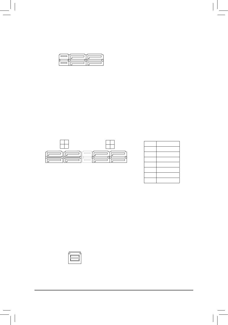
11) SATA3 0/1/2/3/4/5/6/7 (SATA 6Gb/s Connectors)
The SATA connectors conform to SATA 6Gb/s standard and are compatible with SATA 3Gb/s and SATA
1.5Gb/sstandard.EachSATAconnectorsupportsasingleSATAdevice.TheAMDChipsetsupportsRAID0,
RAID1,andRAID10.RefertoChapter3,"ConguringaRAIDSet,"forinstructionsonconguringaRAID
array.
Pin No. Denition
1 GND
2 TXP
3 TXN
4 GND
5 RXN
6 RXP
7 GND
SATA3
2 0
3 1
7
7
DEBUG
PORT
G.QBOFM
DEBUG
PORT
G.QBOFM
12) U2_32G (U.2 Connector)
The U.2 connector supports a single U.2 device.
F_USB30
F_U
B_
F_ F_
_
B
BS_
B
SB_
B
_S
S_
_
B
_U
_
B
S
123
123
123
123
1
1
1
1
BSS
S
_S
SSU
1 2 3
S3
BSSS
U
__ 3
F_USB3F
S _
S _
S _
SF
B_
B_
F
_0
S
S
_0F
_F
_
_
__B
U
S _S
_
USB0_B
B_
F_USB3
10) SATA EXPRESS (SATA Express Connectors)
Each SATA Express connector supports a single SATA Express device.
F_USB30
F_U
B_
F_ F_
_
B
BS_
B
SB_
B
_S
S_
_
B
_U
_
B
S
123
123
123
123
1
1
1
1
BSS
S
_S
SSU
1 2 3
S3
BSSS
U
__ 3
F_USB3F
S _
S _
S _
SF
B_
B_
F
_0
S
S
_0F
_F
_
_
__B
U
S _S
_
USB0_B
B_
F_USB3
SATA3
- 17 -
13) M2F_32G (M.2 Socket 3 Connector)
TheM.2connectorsupportsM.2SATASSDsandM.2PCIeSSDsandsupportsSATARAIDconguration
throughtheAMDChipset.PleasenotethatanM.2PCIeSSDcannotbeusedtocreateaRAIDarray.Refer
toChapter3,"ConguringaRAIDSet,"forinstructionsonconguringaRAIDarray.
F_USB30
F_U
B_
F_ F_
_
B
BS_
B
SB_
B
_S
S_
_
B
_U
_
B
S
123
123
123
123
1
1
1
1
BSS
S
_S
SSU
1 2 3
S3
BSSS
U
__ 3
F_USB3F
S _
S _
S _
SF
B_
B_
F
_0
S
S
_0F
_F
_
_
__B
U
S _S
_
USB0_B
B_
F_USB3
80110 60 42
Select the proper hole for the M.2 SSD to be installed and refasten the screw and nut.
Follow the steps below to correctly install an M.2 SSD in the M.2 connector.
Step 1:
Use a screw driver to unfasten the screw and nut from the motherboard. Locate the proper mounting hole
fortheM.2SSDtobeinstalledandthenscrewthenutrst.
Step 2:
Slide the M.2 SSD into the connector at an angle.
Step 3:
Press the M.2 SSD down and then secure it with the screw.
SATA3 0 SATA3 1 SATA3 2 SATA3 3 SATA3 4 SATA3 5 SATA3 6 SATA3 7
M.2 SATA SSD
a a a r a a a a
M.2 PCIe x4 SSD*
a a a a a a a a
M.2 PCIe x2 SSD
a a a a a a a a
No M.2 SSD Installed
a a a a a a a a
a: Available, r: Not available
* ForAMDRyzen
™
processor only.
Connector
Type of
M.2 SSD
Installation Notices for the M2F_32G and SATA Connectors:
Due to the limited number of lanes provided by the Chipset, the availability of the SATA connectors may be
affected by the type of devices installed in the M2F_32G connector. The M2F_32G connector shares bandwidth
withtheSATA33connector.Refertothefollowingtablefordetails.
- 18 -

15) F_AUDIO (Front Panel Audio Header)
ThefrontpanelaudioheadersupportsIntelHighDenitionaudio(HD)andAC'97audio.Youmayconnect
your chassis front panel audio module to this header. Make sure the wire assignments of the module
connector match the pin assignments of the motherboard header. Incorrect connection between the module
connector and the motherboard header will make the device unable to work or even damage it.
For HD Front Panel Audio:
For AC'97 Front Panel Audio:
• The front panel audio header supports HD audio by default.
• Audio signals will be present on both of the front and back panel audio connections simultaneously.
• Some chassis provide a front panel audio module that has separated connectors on each wire
instead of a single plug. For information about connecting the front panel audio module that has
different wire assignments, please contact the chassis manufacturer.
Pin No. Denition
1 MIC2_L
2 GND
3 MIC2_R
4 NC
5 LINE2_R
6 Sense
7 FAUDIO_JD
8 No Pin
9 LINE2_L
10 Sense
Pin No. Denition
1 MIC
2 GND
3 MIC Power
4 NC
5 LineOut(R)
6 NC
7 NC
8 No Pin
9 Line Out (L)
10 NC
F_USB30
F_U
B_
F_ F_
_
B
BS_
B
SB_
B
_S
S_
_
B
_U
_
B
S
123
123
123
123
1
1
1
1
BSS
S
_S
SSU
1 2 3
S3
BSSS
U
__ 3
F_USB3F
S _
S _
S _
SF
B_
B_
F
_0
S
S
_0F
_F
_
_
__B
U
S _S
_
USB0_B
B_
F_USB3
9 1
10 2
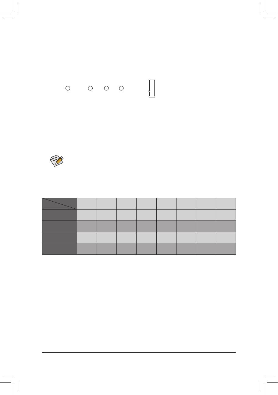
14) F_PANEL (Front Panel Header)
Connect the power switch, reset switch, speaker, chassis intrusion switch/sensor and system status indicator
on the chassis to this header according to the pin assignments below. Note the positive and negative pins
before connecting the cables.
System Status LED
S0 On
S3/S4/S5 Off
• PW(PowerSwitch,Red):
Connects to the power switch on the chassis front panel. You may
congurethewaytoturnoffyoursystemusingthepowerswitch(refer
toChapter2,"BIOSSetup,""Power,"formoreinformation).
• SPEAK (Speaker, Orange):
Connects to the speaker on the chassis front panel. The system reports
system startup status by issuing a beep code. One single short beep
will be heard if no problem is detected at system startup.
• PLED/PWR_LED (Power LED, Yellow/Purple):
Connects to the power status indicator
on the chassis front panel. The LED is on
when the system is operating. The LED is
off when the system is in S3/S4 sleep state
or powered off (S5).
• HD (Hard Drive Activity LED, Blue):
Connects to the hard drive activity LED on the chassis front panel. The LED is on when the hard drive is
reading or writing data.
• RES (ResetSwitch,Green):
Connects to the reset switch on the chassis front panel. Press the reset switch to restart the computer if the
computerfreezesandfailstoperformanormalrestart.
• CI (Chassis Intrusion Header, Gray):
Connects to the chassis intrusion switch/sensor on the chassis that can detect if the chassis cover has been
removed. This function requires a chassis with a chassis intrusion switch/sensor.
• NC (Orange): No Connection.
NC
NC
Power LED
DEBUG
PORT
G.QBOFM
1
2
19
20
CI-
CI+
PWR_LED-
PWR_LED+
PLED-
PW-
SPEAK+
SPEAK-
PLED+
PW+
Power LED
HD-
RES+
HD+
RES-
Hard Drive
Activity LED
Reset
Switch
Chassis Intrusion
Header
Power Switch
Speaker
PWR_LED-
The front panel design may differ by chassis. A front panel module mainly consists of power switch,
resetswitch,powerLED,harddriveactivityLED,speakerandetc.Whenconnectingyourchassis
front panel module to this header, make sure the wire assignments and the pin assignments are
matched correctly.
- 19 -
Pin No. Denition Pin No. Denition
1 VBUS 11 D2+
2 SSRX1- 12 D2-
3 SSRX1+ 13 GND
4 GND 14 SSTX2+
5 SSTX1- 15 SSTX2-
6 SSTX1+ 16 GND
7 GND 17 SSRX2+
8 D1- 18 SSRX2-
9 D1+ 19 VBUS
10 NC 20 No Pin
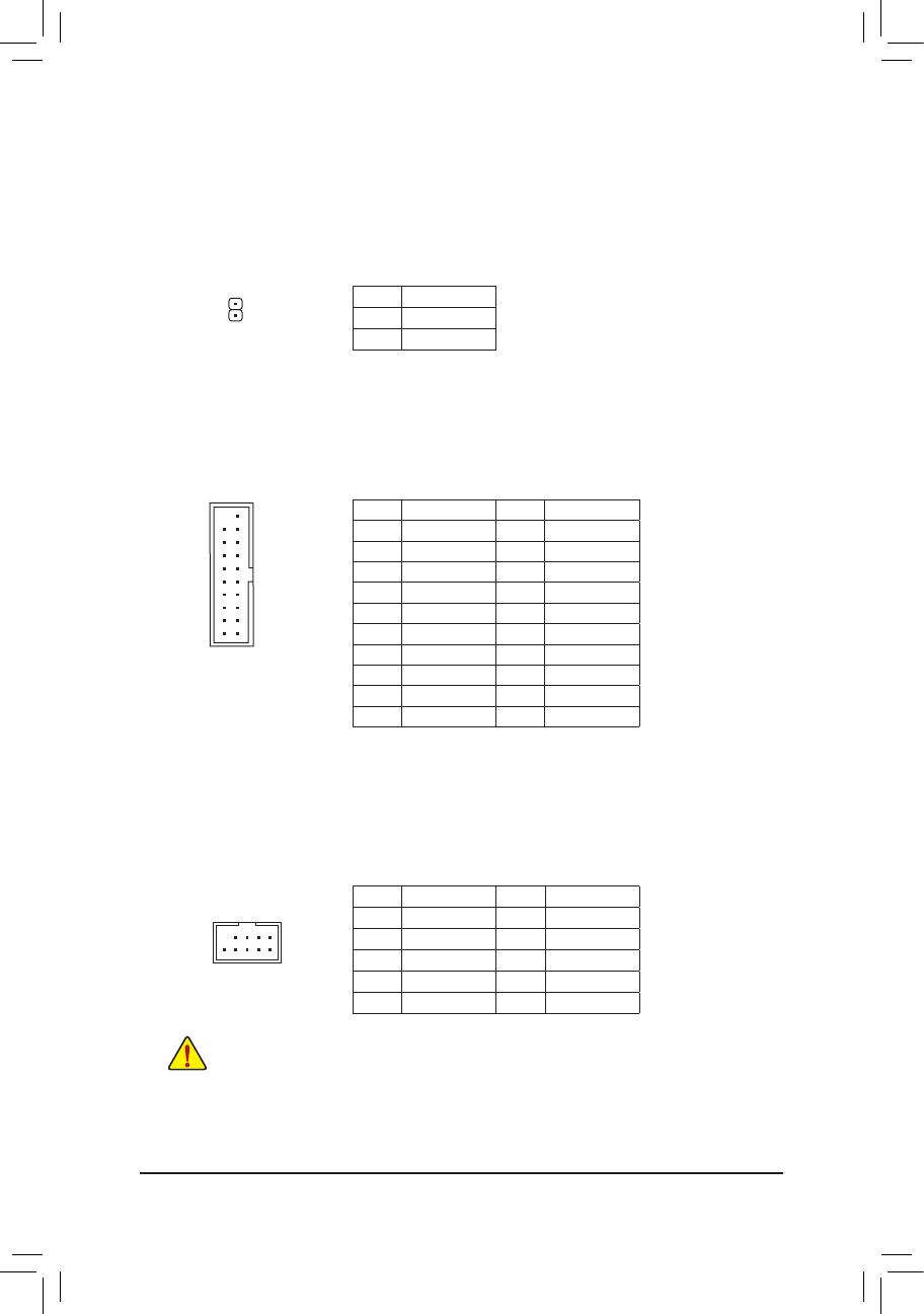
17) F_USB30_1/F_USB30_2 (USB 3.1 Gen 1 Headers)
TheheadersconformtoUSB3.1Gen1andUSB2.0specicationandcanprovidetwoUSBports.For
purchasingtheoptional3.5"frontpanelthatprovidestwoUSB3.1Gen1ports,pleasecontactthelocal
dealer.
18) F_USB1/F_USB2 (USB 2.0/1.1 Headers)
TheheadersconformtoUSB2.0/1.1specication.EachUSBheadercanprovidetwoUSBportsviaan
optional USB bracket. For purchasing the optional USB bracket, please contact the local dealer.
Pin No. Denition Pin No. Denition
1 Power (5V) 6 USB DY+
2 Power (5V) 7 GND
3 USB DX- 8 GND
4 USB DY- 9 No Pin
5 USB DX+ 10 NC
• Do not plug the IEEE 1394 bracket (2x5-pin) cable into the USB 2.0/1.1 header.
• Prior to installing the USB bracket, be sure to turn off your computer and unplug the power cord
from the power outlet to prevent damage to the USB bracket.
16) SPDIF_O (S/PDIF Out Header)
This header supports digital S/PDIF Out and connects a S/PDIF digital audio cable (provided by expansion
cards) for digital audio output from your motherboard to certain expansion cards like graphics cards and
sound cards. For example, some graphics cards may require you to use a S/PDIF digital audio cable for
digital audio output from your motherboard to your graphics card if you wish to connect an HDMI display
to the graphics card and have digital audio output from the HDMI display at the same time. For information
about connecting the S/PDIF digital audio cable, carefully read the manual for your expansion card.
Pin No. Denition
1 SPDIFO
2 GND
1
F_USB30
F_U
B_
F_ F_
_
B
BS_
B
SB_
B
_S
S_
_
B
_U
_
B
S
123
123
123
123
1
1
1
1
BSS
S
_S
SSU
1 2 3
S3
BSSS
U
__ 3
F_USB3F
S _
S _
S _
SF
B_
B_
F
_0
S
S
_0F
_F
_
_
__B
U
S _S
_
USB0_B
B_
F_USB3
10
20 1
11
DEBUG
PORT
G.QBOFM
10
9
2
1
- 20 -
/