Page is loading ...

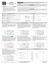
EMS447 and EMS448 Models
Operation Instructions Section
“2”
Standard
Program #01 (A94035) V12 and Later
EMS Modes of Operation
The EMS447 and EMS448 monitor your engine/motor conditions and count
down the service reminders. When a shutdown occurs, the fuel valve will turn off
and the display will show the cause of shutdown. TOA switch must be moved to
“OFF” to reset.
The EMS447 and EMS448 have two standard modes of operation which can be
configured in the S-Numbers, these modes of operation are described as follows:
Manual Mode:
When this mode is selected, the EMS performs as a
monitoring engine panel. It will alarm when faults are detected and initiate
shutdowns based on shutdown switches and gage senders. It will also remind
you when service is required for your equipment.
Automatic Mode:
In the Automatic Mode, two of the shutdown inputs
available in the Manual Mode are redefined. Instead of shutdowns for V
-belt
Break
and Low Oil Level, automatic throttling inputs are available.
All S-numbers are used and must be configured in the Automatic mode.
Sequence of Operations
Automatic Mode of Operation
(TOA switch is in Auto, see Scrolling Main Displays, 8. Selector, p-2.)
I. A Start Signal is received
a.
The start delay begins timing. If the start signal is sustained throughout
this delay, step b. is executed. If the start signal is not sustained throughout
this delay, nothing happens.
b.
The prelube/glowplug output turns on throughout the prelube/glowplug delay.
c.
The Fuel and Crank outputs turn on. The crank output turns on for the
adjustable crank time. It then turns off for the adjustable rest time. If the
engine starts, step d. is executed. If the engine does not start in the
adjustable number of cranking attempts, the unit will display
OVERCRANK, turn off the fuel and crank outputs, and turn on the common
fail output. If the engine false starts, the unit will wait through the adjustable
recrank delay before attempting another engine crank.
d.
When the unit senses an engine RPM higher than the crank stop RPM, the
crank and glowplug outputs turn off and the following begin timing:
1. Internal hourmeter.
2. Lockout Delay. Low Oil Pressure and High Engine Temperature
shutdowns are locked out during this delay.
3. Warm-up Delay.
*
e.
The unit signals the engine to throttle up to the warm-up RPM.
*
f.
Once the warm-up delay expires, the EMS signals the engine to throttle up
to Minimum RPM and the clutch output turns on. If the engine throttling
inputs call for an engine increase or decrease, the unit will signal the engine
to respond accordingly.
NOTE: The EMS will always try to throttle the engine between the minimum and
maximum RPM set-points when at the AT-LOAD state.
II. A Stop Signal is received
a.
The stop delay begins timing. If the stop signal is sustained through the
stop delay, step b. is executed. If the stop signal is not sustained through
the stop delay, the unit will continue to run.
b.
The Cooldown delay begins timing.
*
c.
The unit signals the engine to throttle down to an idle.
**
d.
When engine speed reaches the clutch release RPM, the clutch output turns off.
e.
When the cooldown delay expires, the following items occur:
1. Fuel valve turns off.
2. Internal hourmeter stops timing.
f.
The unit is ready for another start signal. If the TOA switch is moved to the
TEST position, delay on start and stop will be ignored. The unit will start
normally and run through the sequence. When TOA switch is moved to OFF,
the unit will signal the engine to shut down without a cooldown period.
Manual Mode of Operation
In the manual mode, the unit gets its power from the ignition position of the engine
start key switch. The following sequence occurs when the unit first powers up.
I. Power is Supplied to the EMS
a.
Fuel
valve output turns on.
b.
T
he “Failed To Start” Delay will begin timing (fixed to 5 minutes).
If the engine is not started within 5 minutes, “Failed To Start” is displayed
and the fuel valve is turned off.
c.
W
hen the engine speed is sensed to meet or exceed the Crank Stop set-
point, the following delays will begin timing.
1. Internal hourmeter.
2. Lockout Delay. Oil pressure and engine temperature shutdowns are
locked out during this delay. The unit must sense an engine RPM
higher than the crank stop RPM before this delay expires or it will turn
off the fuel valve and show No Speed Signal.
II. Key Switch is turned Off
(power removed from EMS)
a.
F
uel valve output turns off.
Operating the Interface
By using the three membrane buttons and the liquid crystal display, you can make
set-point changes, acknowledge alarms, and scroll through the display.
The graphic below shows the display and buttons.
●
The ENTER
(EXIT) button is used to confirm a set-point, get into and out of
a display and to acknowledge alarms.
▲
The YES
(INCREMENT) button is used to scroll up the display, to select
messages, and enter value increments.
▼
The NO (DECREMENT) button is used to scroll down the display, to select
messages, and enter value decrement.
EMS-94132N
Revised 6-03
Section 40
(00-02-0201)
EMS
YES
NO
BACK
DECREMENTNEXTEXIT
INCREMENTENTER
SCROLL
TO EXIT
Controller
®
DISPLAY WINDOW
ENTER
BUTTON
YES
BUTTON
NO
BUTTON
* When equipped with Murphy AT-67207 or other throttling device.
** When equipped with Murphy CO3 or other clutch operator device.
Caution: Certain danger to human safety and to equipment
such as applied in mobile or marine application may occur if
some equipment is stopped without prewarning. In those cases
it is recommended that monitored functions be limited to
alarm-only or to alarm before shutdown.
EMS-94132N page 1 of 12

Scrolling Main Displays
During normal operation, the EMS allows you to scroll through a number of
informative displays. You can manually scroll through monitored information by
pressing
▲
or
▼
buttons, or you may set the unit for automatic scrolling.
While scrolling, the EMS remains fully operational. When a shutdown occurs or a
service reminder comes due, the unit will display the corresponding information
regardless of the scrolling mode. When first powered up, the EMS will delay for one
minute before starting to scroll. When the scrolling mode is changed a 10 second
delay must time out before scrolling resumes.
To set the Automatic scroll, press the
●
and
▲
buttons simultaneously. To set the
Automatic scroll mode to off, press
●
and
▼
buttons at the same time. The
Automatic scroll off enables you to Manually scroll the unit. See displays listing and
explanation below:
1. MURPHY EMS
This is the first line of the title page.
2. PROGRAM #01
This is the second line of the title page. It shows which program is installed
in your unit. This information is helpful when calling for technical assistance.
3. RUN HOURS XXXX.X
This is your on board hour meter. It digitally displays the number of hours
your engine has been running. All the service reminders are based on the
elapsed time on the hourmeter.
4. BATTERY XX.X VDC
This displays your system voltage.
5. ENG SPD XXXX RPM
This displays the current engine RPM. Decisions to stop cranking and
shutdown on overspeed / underspeed are based on this number. Remember
to calibrate this in the S-numbers.
6. OIL PR XXX PSI
This displays the current engine oil pressure as sensed from an electric
gauge sender, or pressure transmitter. Shutdowns based on oil pressure
reference this number.
7. ENG TEMP XXX °F
This displays the current engine temperature as sensed from an electric
gauge sender. The unit will signal the engine to shutdown if this
temperature reading exceeds the shutdown point selected in S10.
8. SELECTOR - XXXX
(Replaced with MANUAL MODE when unit is used as a manual panel)
There are three positions on the selector switch that are displayed on this
line: TEST, OFF and AUTO or (TOA). When this window shows AUTO,
your TOA switch is in the AUTO position. When in AUTO, the unit is
ready to start the engine or already has started it. When this window shows
OFF, your TOA switch is in the OFF position. The unit will not initiate an
auto start with the switch in the OFF position. If the switch is moved to the
OFF position while the engine is running, the unit will signal the engine to
stop. When this window shows TEST, your TOA switch is in the TEST
position. When the switch is flipped to TEST, the unit will start the engine
as if a start signal had been received; regardless of the start/stop contacts.
9. ST: XXXXXXXXXX
ST stands for STATE. This window shows what state your controller is in.
States include the following: NOT READY, PANEL READY, START DLY,
PRELUBE, CRANK ON, CRANK OFF, WARMUP, AT LOAD,
SHUTDOWN, STOP DLY and COOLDOWN.
NOT READY: This state occurs when the selector is in the OFF position. It
means that the panel is not ready to run in Automatic mode.
PANEL READY: This state occurs when the selector is in the AUTO position
and no shutdowns have occurred. It means that the panel is ready to run in
Automatic mode.
START DLY: This state occurs when a start signal is sensed and the start delay
is timing. The start signal must be present throughout this delay before the
unit goes to the next state.
PRELUBE: This state occurs after the Start Delay expires. During the Prelube
state, the prelube output is turned on.
CRANK ON: This state occurs after Prelube Delay expires. During Crank On
state, the unit energizes the starter circuit and attempts to start the engine.
CRANK OFF: This state occurs after the Crank On state if the unit senses that
the engine has not started. During the Crank Off state, the unit removes
power from the starter circuit to cool off the starter before another cranking
attempt is made.
WARMUP: This state occurs after the unit senses that the engine has started.
During this state, the unit throttles the engine
*
to the warmup RPM and
stays at this engine speed until the Warmup Delay expires. The Lockout
Delay also begins timing when the Warmup State begins.
AT LOAD: This state occurs after the Warmup state concludes. It can also
occur if a start signal is received during the Cooldown state (see Cooldown
below). When the At Load state first begins, the clutch circuit is activated
and the unit brings the engine
*
speed to Minimum RPM or higher,
depending on system demand.
STOP DLY: This state occurs when a stop signal is sensed and the stop delay is
timing. The stop signal must be present throughout this delay before the
unit goes to the next state.
COOLDOWN: This state occurs after the Stop Delay has expired. During the
Cooldown state, the unit throttles the engine
*
to an idle. As the engine
RPM passes through the Clutch Release RPM, the unit will deactivate the
clutch circuit. If a start signal is received during the Cooldown state, the
unit will switch to the At Load state and ignore the Warm-up state.
SHUTDOWN: This state occurs if a shutdown condition is detected. Reasons
for shutdown include low oil pressure, high engine temperature, overspeed,
etc. During this state, the engine is signalled to shutdown and all start
signals are ignored until the unit is reset by moving the selector to the OFF
position and then back into AUTO or TEST.
10. CHG OIL XXX HRS
This display shows the number of running hours remaining before the oil
must be changed in the engine.
11. OIL FLT XXX HRS
This display shows the number of running hours remaining before the oil
filter on the engine must be changed.
12. FUEL FLT XXX HRS
This display shows the number of running hours remaining before the fuel
filter on the engine must be changed.
13. AIR CLNR XXX HRS
This display shows the number of running hours remaining before the air
cleaner on the engine must be serviced or changed.
14. SERV BAT XXXX HRS
This display shows the number of running hours remaining before the
engine cranking battery must be serviced or changed.
Service Reminders
The EMS has the above built in service reminders. When a service reminder
comes due, the EMS will stop scrolling and display the service reminder
message. If you cannot perform the service at that moment, you may press the
●
(ENTER)
button and the message will go away for 4 hours and normal
scrolling will resume within 10 seconds approximately.
Once you perform the service, enter the P-Numbers and select the service that is
due. Toggle the
(NO)
to a
(YES)
and the count down Timer will reset to the
number of hours programmed in the S-Numbers.
Loss of Sender Feature
If the EMS senses that a sender wire has broken or the value from the sender is
out of known bounds, the EMS will display a “Loss of Sender” alarm message
and initiate a shutdown. There are alarms for loss of temperature sender, oil
pressure sender and the magnetic pick-up speed sensor.
If you get a lost sender message for temperature or pressure, check the
connections between the controller and the sender. Also check that the sender has
a good ground. If the alarm is for the magnetic pick-up, confirm you are getting at
* When equipped with Murphy AT-67207 or other throttling device.
EMS-94132N page 2 of 12

least 2 Vrms from the magnetic pick-up.
How to access the S-numbers
Also refer to the “Quick-reference” sheet supplied with these instructions.
1.
Press the
▼
button until the title page appears.
2.
Press the
●
button until the entry code screen appears.
3.
Press the
▲
or
▼
buttons until the corresponding entry code is displayed.
4.
Press the
●
button once, the S-numbers main menu will be displayed.
5.
Now that you are in the S-numbers, you can go to a specific function by
pressing the
▲
or
▼
buttons then pressing the
●
button to enter the
specific function. Now you can increase, toggle, or decrease the setpoint.
All Setpoints use the above described procedure. You can exit the set-up mode by
depressing and holding the
▼
button until the exit screen is displayed.
Now press the
●
button to set the EMS back into the Main Displays. If you forget
to exit the S-numbers menu, the EMS will exit for you after 10 minutes.
S-Numbers Description and Listings
The S-numbers are used for customizing the controller to your specific engine.
Included in the S-numbers are variables such as crank / rest times and warm-up /
cool-down times. These S-Numbers must be set before trying to use the unit to
auto start your engine. Following is a list of available S-Numbers and a short
description of the function of each. The Factory Default values are shown in bold
parentheses; the Adjust Range values are shown in standard parentheses.
S0 CIRCLE = EXIT
Used to exit the S-number setup mode.
S1 LINE SELECT
Used to change what is displayed on the top line throughout your S-number
editing session. Your choices include: Engine Speed, Run Hours, Oil Pressure,
Engine Temperature, and Input / Output status. The input and output status
information will show an X if that particular input is active or output is ON. If
there is no input or the output is OFF, the unit will display an O. This can be
used for testing wiring before starting the engine. For more information, see
the section titled “Double Checking Your Wiring”.
S2 SPEED CALIB (120.00 PULS)
This setting (1.00 to 320.00), is used to calibrate the speed signal so that
the unit will display engine RPM. This setting must be adjusted for items
such as crank stop RPM and OVERSPEED RPM to work. Simply enter the
number of Pulses per revolution the magnetic pickup or alternator supplies
to the EMS. Another way to set this variable is to get the engine running at
a known RPM and then change the number until the top line matches your
known RPM. The resulting number is the pulses per revolution.
S3 OVERSPEED (2000 RPM)
This setting allows you to enter the highest speed the engine can run before
damage is caused (0 to 10,000). If the unit senses that the engine has
exceeded this speed, it will signal the engine to shutdown.
S4 UNDERSPEED (0 RPM)
If the engine speed dips to the RPM in this set-point, an automatic
shutdown will be initiated (0 to 5,000). If you do not want to use this
feature, change this variable to 0.
S5 LOCKOUT DELAY (30 SEC)
This delay (2 to 60), is used to ignore conditions such as low oil pressure when
the engine first starts to allow the pressure time to reach its normal operating
range.
S6 LOP @ LOW SPD (15 PSI)
The EMS gives you two oil pressure shutdown points (0 to 1000). For
engines that develop very little oil pressure at an idle, you put a lower
shutdown setting in this set-point. The unit automatically changes the
shutdown point between the Low Speed Shutdown point and the High
Speed Shutdown point.
S7 LOP @ HI SPD (30 PSI)
This set-point (0 to 1000), is the higher oil pressure shutdown point that is
referred to in S-number 6. This is the point that you want the engine to shutdown
during normal high speed engine operation. By shutting down the engine at a
higher oil pressure, you can avert damage that could be caused by waiting to shut
down the engine at the lower set-point needed to accommodate an idle.
S8 LOP LO SPEED (600 RPM)
Set this to your engine idle speed (0 to 10,000). If the engine is running at
this speed, an idle for example, and the oil pressure reaches the set-point
selected in S6, the unit will initiate an automatic shutdown.
S9 LOP HI SPEED (1600 RPM)
Set this to your engine maximum speed (0 to 10,000). If the engine is
running at this speed, and the oil pressure reaches the set-point selected in
S7, the unit will initiate an automatic shutdown. The Graph below shows
how the set-point changes between your high speed set-point and low
speed set-point. As the engine speed increases, the unit automatically raises
the oil pressure shutdown set-point along a straight line between the two
set-points you entered. This graph represents the following set-points: S6 is
set to 5, S7 is set to 30, S8 is set to 600, and S9 is set to 2000.
NOTE: Once the speed reaches the high speed set-point, the oil pressure
shutdown point will not increase any higher.
S10 HI ENG TEMP (220 °F)
Adjust this setting (0 to 400), to the engine temperature you do not want to
exceed. If the unit senses an engine temperature higher than this set-point,
it will initiate an automatic shutdown.
S11 PRESS UNITS (PSI)
Select the units of pressure you would like displayed on the digital read
out. Your choices are: PSI (Pounds Per Square Inch); KPA (Kilo Pascals);
BARS (Bar); KG❐CM (Kilograms Per Square Centimeter).
NOTE: Also included are choices for selecting a bar graph of the units specified
above.
S12 TEMP UNITS (°F)
Select the units of temperature you would like displayed on the digital read
out. Your choices are: °F (Fahrenheit); °C (Celsius)
NOTE: Also included are choices for selecting a bar graph of the units specified
above.
S13 CRK STOP (300 RPM)
This RPM set-point is used to adjust where the unit releases the starter during
cranking (0 to 9999). Set this to the RPM the engine attains just as it starts.
This way, the starter is not engaged unnecessarily after the engine starts. You
must also set this set-point to the speed you release the starter while cranking.
This is how the unit senses whether the engine is running or not. You will get
a NO SPEED SIGNAL shutdown if this is adjusted to high.
S14 SPARE 1 TYPE (DLY ALM & SHTDWN)
S14 selects how the spare 1 terminal will handle an input signal. Your
choices are: Immediate alarm only, Immediate alarm & Shutdown,
Immediate alarm before shutdown, Delay alarm only, Delay alarm &
shutdown, and Delay alarm before shutdown. An immediate type alarm,
shutdown or both will be processed whenever the input is active. A delay
type alarm, shutdown or both will be processed after the Lockout Delay has
expired (S5). The alarm before shutdown is fixed at 30 seconds. The next
option is RPM LIMIT ENABLE, when selected, an input to spare 1
terminal (spare 1 input) will signal the unit to throttle the engine
*
to the
setting in S34. When this input is not grounded, the unit will throttle the
engine to the setting in S33. The engine must be in AT LOAD state for this
CAUTION:
THE S-NUMBERS CONTAIN CRITICAL
OPERATING PARAMETERS. ITEMS SET IMPROPERLY
CAN CAUSE SERIOUS DAMAGE TO THE ENGINE.
2500 2000 1500 1000 500
0
10
20
30
40
Shutdown Setting
OIL PRESSURE PSI
R. P. M.
* When equipped with Murphy AT-67207 or other throttling device.
EMS-94132N page 3 of 12

throttle type to take effect. (This type will not function in Manual Mode.)
Your final option is LOW OIL LEVEL. When this is selected, the unit will
display LOW OIL LEVEL on the screen and shut the engine down if an
input is sensed on the SPARE 1 terminal. This is an Immediate alarm and
shutdown type.
S15 OIL PRESSURE TYPE
Enter in the type of oil pressure sensing device being used.
Your choices include: SENDER: The program would
accommodate the Murphy ES2P electric sender. XDUCER:
The program would accommodate the Murphy PXMS
pressure transducer. DIGITAL: The program would
accommodate the Murphy 20P pressure Swichgage. Factory
set to SENDER.
NOTE: LK2 #2 must be in the sender position for the “sender” or “digital”
choices. It must be in the 4-20 position for the “xducer” choice.
S16 OIL PRESSURE SLOPE
With battery power applied and no pressure applied, enter
the value displayed in the top line on the bottom line. This
should be 51 if the transducer is producing exactly 4 ma. at
zero pressure. This S# is not available if either SENDER or
DIGITAL is selected in S15. Factory set to 51.
S17 OIL PRESSURE MAX
Enter in the maximum range of the PXMS oil pressure
transducer. Example: PXMS-100 enter 100 in this set point.
This S# is not available if either SENDER or DIGITAL is
selected in S15. Factory set to 100.
S18 CHANGE OIL
Set the interval in engine running hours you wish to be
prompted to change your engine oil. Factory set to 500.
S19 CHG OIL FLTR
Set the interval in engine running hours you wish to be
prompted to change your engine oil filter. Factory set to 500.
S20 CHG FUEL FLT
Set the interval in engine running hours you wish to be
prompted to change your engine fuel filter. Factory set to 1000.
S21 SERV AIR CLN
Set the interval in engine running hours you wish to be
prompted to service your engine air cleaner. Factory set to 10.
S22 SERV BATTERY
Set the interval in engine running hours you wish to be
prompted to service your cranking battery. Factory set to 120.
NOTE: After service reminder time values have been set, the
new values will not take effect (become active) until they have
also been acknowledged in P-Numbers P-15 through P-19.
S23 PANEL MODE
You have two options: MANUAL or AUTOMATIC. When
Manual is selected, the unit will function as a standard
engine monitoring panel. You must manually start the
engine and throttle it to the desired speed. It will initiate
shutdowns when faults are detected. Set-points relating to
the Automatic mode will no longer display when this mode
is selected. When AUTOMATIC is selected, the unit will
perform all engine control automatically. Factory set to
MANUAL.
S24 WARMUP DLY
You can adjust this variable to the number of seconds you
want your engine to warm-up before it engages the clutch
and throttles up to an at load condition, or goes to the “at
load” state (adjustable from 1 to 300 seconds). Factory set
to 30.
S25 COOLDOWN DLY
You can adjust this variable to the number of seconds you
wish to cool down your engine before it shuts off after a
stop signal is received (adjustable from 1 to 300 seconds).
Factory set to 60.
S26 PRELUBE DLY
If you have the requirement for prelube or possibly a
glowplug, you can use this delay. Set in the number of
seconds you wish the unit to turn on this output before it
initiates a crank. Factory set to 1.
S27 ENG STRT DLY
Set this delay on engine start to the number of seconds that
the start signal must be present before the unit accepts it and
initiates an auto start sequence (adjustable from 1 to 300
seconds). Factory set to 1.
S28 ENG STOP DLY
Set this delay on engine stop to the number of seconds that
the stop signal must be present before the unit accepts it and
initiates a stop sequence (adjustable from 1 to 300 seconds).
Factory set to 1.
S29 CRANK TIME
Set this delay to the desired amount of time you want each
engine cranking attempt to last. Consult your engine manual
for recommended cranking and resting times (adjustable
from 1 to 300 seconds). Factory set to 10.
S30 REST TIME
Set this delay to the desired amount of time you want each
rest period between cranking attempts to last. Consult your
engine manual for recommended resting and cranking times
(adjustable from 1 to 300 seconds). Factory set to 10.
S31 RECRANK DLY
This delay is used to adjust the amount of time the unit will
wait for the engine to stop moving before attempting
another crank if a false start occurs. A false start is when the
engine starts but then dies before the LOCKOUT DELAY
has expired (adjustable from 1 to 300 seconds). Factory set
to 10.
S32 CRK ATTEMPTS
Set the number of attempts you would like the controller to
try an engine start. If the engine fails to start after the
number of attempts you have selected, it will fail the engine
and display OVERCRANK on the front display. This
shutdown requires a manual reset. Factory set to 6.
S33 MIN ENG RPM
Minimum engine RPM is the speed at which your engine
must run for it’s driven equipment to start performing work.
For example, in a pumping application, minimum engine
RPM is the speed at which an engine must run for fluid to
begin being pumped. Set this variable to that speed. Factory
set to 900
S34 MAX ENG RPM
Maximum engine RPM is the speed at which engine driven
pump performance peaks. If the engine exceeds this speed,
pump performance starts to deteriorate. This would be at the
peak of a pump curve, for example. Set this set-point to that
peak speed. For auto throttling at load, the controller will
vary your engine speed between minimum and maximum
RPM. Factory set to 1600.
S35 WARMUP RPM
You can set a specific speed you would like the engine to
run during the warm-up time delay in this set-point. Consult
your engine manual for the optimum warm-up speed.
Factory set to 700.
* When equipped with Murphy AT-67207 or other throttling device.
EMS-94132N page 4 of 12

S36 RATE INC RPM
This set-point is used to customize how fast or slow you
wish the unit to increase the engine speed during throttling.
Experiment with this number until the desired throttling is
achieved. Factory default for this set-point is 10 RPM per
second. Factory set to 10.
S37 RATE DEC RPM
This set-point is used to customize how fast or slow you
wish the unit to decrease the engine speed during throttling.
Experiment with this number until the desired throttling is
achieved. Factory default for this set-point is 10 RPM per
second. Factory set to 10.
S38 CLUT REL RPM
During cooldown, the unit brings the engine to an idle.
While it is throttling down, it passes through the clutch
release RPM and drops out the clutch. Set this point to the
RPM you would like the unit to automatically release the
clutch during Cooldown. Factory set to 800.
S39 STRT/STOP TYPE
This set-point allows you to configure the type of automatic
start / stop inputs you will use. If this set-point is adjusted to
OPL, a momentary input to terminal 1(447), (31 on 448),
(analog input 4 as a switch input) will cause a start and a
momentary input to terminal 15(447), (34 on 448) (analog
input 5 as a switch input) will cause a stop. The momentary
input must be maintained for the length of the start or stop
delay. If this set-point is adjusted to 1 MAINTAIN CNTCT,
a start input must be present the entire time a run condition
is required on terminal 1(447), (31 on 448), (analog input 4
as a switch input). When this input is taken away, the unit
interprets this as a stop signal. If this set-point is adjusted to
2 MAINTAIN CNTCT, a start input must be present on both
1(447), (31 on 448), (analog input 4 as a switch input) and
15(447), (34 on 448), (analog input 5 as a switch input)
before the unit will acknowledge a start. A stop is initiated
after both inputs are removed. Factory set to OPL
START/STOP.
S40 THR MIN PULS
This set-point is used to further customize the way the unit
throttles your engine. Higher numbers cause the throttling
outputs to stay active for longer periods of time when the
unit demands an increase or decrease in the throttling. If it
hunts around the set-point, lower the setting. If the engine
never reaches the set-point, raise the number. Factory set to
700.
S41 THR FDBK DLY
This set-point adjusts the amount of time in quarter seconds
that the controller waits to sample the change made from the
previous throttle pulse. Lower numbers cause less of a wait
than larger numbers. If the system pressure, for example,
takes quite a long time to change based on speed changes
from the engine, this set-point should be increased. On the
other hand, if the system pressure reacts quickly with changes
in engine RPM, lower the set-point. Factory set to 2.
S42 THR SEN SITVY
This set-point adjusts the throttle sensitivity when it closes in on
the desired set-point. Higher numbers cause it to make more
coarse signal adjustments when approaching a set-point than
lower numbers. This set-point is used to keep the unit from
overshooting or undershooting a set-point. If it hunts around the
set-point, lower the setting. If the engine never reaches the set-
point, raise the number. Factory set to 700.
How to access the P-numbers
Also refer to the “Quick-reference” sheet supplied with this installation.
1.
Press the
▼
button until the title page appears.
2.
Press the
●
button until the entry code screen appears.
3.
Press the
▲
or
▼
buttons until the corresponding entry code is displayed.
4.
Press the
●
button once, the P-numbers main menu will be displayed.
5.
Now that you are in the P-numbers, you can go to a specific function by
pressing the
▲
or
▼
buttons then pressing the
●
button to enter the
specific function. Now you toggle, or acknowledge service reminders.
All P Numbers
use the above described procedure. You can exit this mode by
depressing and holding the
▼
button until the exit screen is displayed.
Now press
●
to set the EMS back into the Main Displays. If you forget to exit the
P-numbers menu, the EMS will exit for you after 10 minutes.
P-Numbers Description and Listings
The P-numbers are used to acknowledge service reminders and accessing the shutdown
history list. Following is a list of P-number information and acknowledgments.
P0 CIRCLE = EXIT
Used to exit the P-number editing mode.
P1 LINE 1 SELECT
Used to change what is displayed on the top line throughout your P-number
editing session. Your choices include: Engine Speed, Run Hours, Battery
Voltage, Oil Pressure, and Engine Temperature.
P2 OIL PR @ SHDW
Shows what the engine oil pressure was when the unit initiated the last
shutdown. To view the information, press the
●
button.
P3 TEMP @ SHDW
Shows what the engine temperature was when the unit initiated the last
shutdown. To view the information, press the
●
button.
P4 TACH @ SHDW
Shows what the engine speed was when the unit initiated the last shutdown.
To view the information, press the
●
button.
P5 LAST SHUTDOWN
Shows what caused the last shutdown and the time in running hours that it
occurred. To view the information, press the
●
button.
P6 THRU P14 ## SHUTDWN
These P-numbers store the 2nd through the 10th cause of shutdown and the
running hours they occurred (to view information, press
●
button).
P15 ACK CHG OIL
This setting allows the user to acknowledge that they have changed the oil
in the engine as prompted by the unit. When this setting is toggled from
NO to YES, the unit resets the counter and will not prompt the user again
until the selected number of running hours has elapsed.
P16 ACK OIL FLTR
This setting allows the user to acknowledge that they have changed the oil
filter as prompted by the unit. When this setting is toggled from NO to
YES, the unit resets the counter and will not prompt the user again until the
selected number of running hours has elapsed.
P17 ACK FUEL FLTR
This setting allows the user to acknowledge that they have changed the fuel
filter as prompted by the unit. When this setting is toggled from NO to
YES, the unit resets the counter and will not prompt the user again until the
selected number of running hours has elapsed.
P18 ACK AIR CLNR
This setting allows the user to acknowledge that they have changed or
serviced the air cleaner as prompted by the unit. When this setting is
EMS-94132N page 5 of 12

toggled from NO to YES, the unit resets the counter and will not prompt
the user again until the selected number of running hours has elapsed.
P19 ACK BATTERY
This setting allows the user to acknowledge that they have serviced /
changed the battery as prompted by the unit. When this setting is toggled
from NO to YES, the unit resets the counter and will not prompt the user
again until the selected number of running hours has elapsed.
P20 PROGRAM #
This indicates what program and version number is installed in your unit.
When you call for help, please have this number available.
General Wiring Precautions
There are several precautions you can take on initial installation to increase
reliability. Many of these steps may take a few extra minutes to do at the time of
installation; however, they can also save headaches in the future. We strongly
recommend that you follow these precautionary steps.
1.
Suppression Diodes
Place suppression diodes across all inductive loads. These loads typically
include pilot relays, solenoid valves, starter solenoids, etc. This helps increase
contact life and eliminate a source of electrical interference.
2.
Wire Power Leads Directly to Battery Post
When hooking your power supply to your EMS447 /448 (Automatic mode) or
Off-On switch (Manual Mode), run your positive and negative wiring directly
to the battery posts. This helps minimize noise generated from battery
chargers and alternators.
3.
Pilot Excessive Loads
Many of the outputs on the EMS controller are rated for low current, control
type loads. Do NOT run high current loads directly to the unit.
4.
Use Stranded Wire for Hook Up
Solid wire transmits vibration and is more likely to crystallize and break
when it is subjected to movement and or vibration.
5.
Wire Standby Battery Charger Directly to Battery
Standby chargers must be wired directly to the battery. Failing to do this may
result in erratic operation due to electric “noise” coupled into the
microprocessor.
6.
Separate VAC and VDC Wiring
Never run AC and DC handling wiring together. AC signals may get coupled
into the control circuits leading to erratic operation.
7.
Special Precaution for Spark Ignition Systems
Spark ignition systems produce high voltage and cause high frequency
interference. Precautions must be taken to protect the EMS. All wiring, and
especially sender and shutdown wiring must be routed away from the ignition
and spark plug wiring. Resistor spark plugs and spark plug wires reduce
electrical interference and are recommended for these applications.
8.
Use Shielded Cable on Magnetic Pick-up
Shielded cable is recommended for connecting the magnetic pick-up to the unit.
This helps prevent signal loss and possible coupling of electrical interference
into the relatively sensitive speed sensing circuit. The shield should only be
grounded on one end. Remember, proper care during installation will help your
EMS controller live a long and trouble-free operating life.
EMS-94132N page 6 of 12
Double Checking your Wiring
The EMS Controller has built in diagnostic information for confirming your wiring
before you attempt to auto start your engine. The diagnostic information is found in
the S-numbers under S1 LINE 1 SELECT. The factory default line 1 display shows
the engine RPM. By scrolling through the displays, you will see the following:
I 1-4 ØØØØ
This represents the 4 standard digital only inputs. A Ø means that the input is not
active. An X means that the input is active. Following is what each input represents:
1.
Auto Position on Toggle Switch
2.
Test Position on Toggle Switch
3.
External Spare 1 Shutdown input
4.
Not Used for This Application
Next screen shows the rest of your inputs:
I 5-12 ØØØØ ØØØØ
5.
Battery Voltage Input (ignore)
6.
Temperature Sender
(For test purposes, you can ground this input
to make sure you have run your wire properly.)
7.
Oil Pressure Sender
(For test purposes, you can ground this input
to make sure you have run your wire properly.)
8.
Low Coolant Level Input
9.
OPL Start Input / Remote S/S Input
10.
OPL Stop Input
11.
OPL Increase Input
(low oil level in Manual mode)
12.
OPL Decrease Input
(V-belt break in Manual mode)
Next screen show your outputs:
O 1-7 ØØØØ ØØØ
1.
Fuel Valve Output
2.
Starter Circuit Output
3.
Common Fail Output
4.
Throttler Decrease Output
5.
Throttler Increase Output
6.
Prelube Output
7.
Clutch Output
Oil pressure 100 PSI
Engine temperature 167 °F
Engine hours 93.5
System voltage 14.0
Engine rpm 1343
Setpoint rpm 700
SELECTOR - TEST
WARMUP
CHANGE OIL
SHUTDOWN INFORMATION
Hours at shutdown 93
Oil pressure shutdown 11 psi
RS485 Output
This program is equipped with computer display capability. By hooking up to a
computer equipped with an RS485 serial port and a communication program like
Procomm Plus or Hyperterminal, you can remotely watch the status of your
engine. The screen output consists of the Engine RPM, Oil Pressure, Engine
Temperature, Running Hours, Target Engine RPM, Engine State, Selector Switch
Position, Current Service Reminders, and a shutdown history log. For proper
display, set your communications package to 9600 baud N-8-1. Shown below is
an example of the generic Input / Output layout for EMS447 and EMS448
models.

EMS-94132N page 7 of 12
Color Code (Option -C)
EMS448 Terminal Designation
1 Black 31 Analog input 4
10
†
Red w/ Black stripe K2
Com 1=6 NO=4 NC=5 Com 2=15 NO=13 NC=14 (K2)
Digital output 2
18 White w/ Green stripe 40 Digital input 3
9 Gray 20 Battery +
15 White w/ Brown stripe 34 Analog input 5
17 White w/ Blue stripe 38 Analog input 2
19 White w/ Red stripe 12 Digital input 4 jumper
21 White w/ Orange stripe 25 Digital output 5
23 White w/ Gray stripe 29 & 30 NO (K7)
*
Digital output 7 jumper
25 White w/ Black/Red 3 RS485 pos. + Comm.
24 White 2 RS485 neg. -- Comm.
EMS447 PIN Num.
447 Relay
Input / Output Designation
EMS447 Pin and Color Codes to EMS448 Terminal Conversion
or
+-
VIOLET
GRAY
PINK
85 86
30 87a
87
12345
BATTERY
BATTERY
CABLES
STARTER
MOTOR
SOLENOID
PILOT
RELAY
ALTERNATOR
BATTERY
TERMINAL
EXCITATION
TERMINAL
REGULATOR
TERMINAL
DIODE
SHIELDED
CABLE
THROTTLE
CONTROL
SENSOR
INCREASE
DECREASE
COOLANT LEVEL
SLOW
FAST
TEST AUTO
OFF
SHUTDOWN
SUMMARY
OUTPUT
+
SPARE EXTERNAL
SHUTDOWN
RED W/ ORANGE STRIP
RED W/ BLACK STRIPE
WHITE / VIOLET STRIPE
YELLOW
GREEN
BLUE
BLACK
WHITE W/ BROWN STRIPE
TAN
RED
RED W/ GREEN STRIPE
WHITE W/ YELLOW STRIPE
WHITE W/ BLUE STRIPE
WHITE W/ GREEN STRIPE
ORANGE
WHITE W/ BLACK STRIPE
WHITE W/ ORANGE STRIPE
WHITE W/ GRAY STRIPE
OIL PRESSURE
SENDER
(100 psi)
TEMPERATURE
SENDER
THROTTLE
CONTROLLER
CLUTCH OPERATOR
PILOT RELAY
PILOT
RELAY
GLOW PLUGS
RS-485
COMM.
SHIELDED
CABLE
PORT
-
WHITE
WHITE W/ BLACK & RED STRIPE
6 AMP
FUSE
WIRES NOT USED BROWN, WHITE W/ RED STRIPE
NOTES: REFER TO S39 (PAGE 5) FOR
START/STOP OPTIONS.
CONNECTION DIAGRAM FOR EMS447
WITH PROGRAM # 01 INSTALLED.
AUTOMATIC MODE ONLY
STARTER
RING GEAR
FLYWHEEL HOUSING
MAGNETIC
PICKUP
SHIELDED
CABLE
FUEL SOLENOID
START
STOP
START STOP
SENSOR
SEE NOTE
+
+
+
+
+
3 AMP
MAX.
+
3 AMP
MAX.
+
3 AMP
MAX.
EMS447 CONNECTOR PINS
11 10 22 13 15 12 16 17 18 20 21 23 24 25148 9 6 5
7 1 3 4
BLUE RED
PXMS-
100
OPTIONAL
OIL PRESSURE
S15=XDUCER
EMS447 AUT
OMATIC MODE
Wiring Diagram (S23=Automatic)
12
†
Red w/ Green stripe K1 21 & 22 NO (K1) Digital output 3
Notes: Digital output 4 can be equipped with EMS448 relay K3–provides N.O. dry contact output at terminals 23/24. Digital output 5 can be equipped with EMS448 relay K4–provides N.O. dry contact at
terminals 25/26.
*
LK1 is on the “OUT” position for this program.
†
Pins 7,10, and 12 are battery positive, relay contact outputs from the EMS447 with LK4, 5, and 6 in the “R” position. LK2 positions
0-7 in “sender” position unless oil pressure “xducer” option chosen, then LK2-2 should be in 4-20 position.
2 Brown 33 (Do Not Connect) Analog input 0 (Internally Connected)
4 Orange 37 Analog input 1
3 Red 35 Analog input 7
5 Yellow 39 Digital input 1
6 Green 11 Digital input 2
7
†
Blue K3
Com 1=B+ NO=8 NC=7 Com 2=18 NO=16 NC=17 (K6)
Digital output 1
8 Violet 20 Battery +
11 Red w/ Orange stripe 9 & 10 Battery --
13 Pink 1 Frequency input
14 Tan 32 Analog input 6
16 White w/ Yellow stripe 36 Analog input 3
22 White w/ Violet stripe 27 & 28 NO (K5) Digital output 6
20 White w/ Black stripe 23 Digital output 4

EMS-94132N page 8 of 12
+-
VIOLET
GRAY
PINK
BATTERY
BATTERY
CABLES
STARTER
MOTOR
SOLENOID
PILOT
RELAY
ALTERNATOR
BATTERY
TERMINAL
EXCITATION
TERMINAL
REGULATOR
TERMINAL
DIODE
RED W/ ORANGE STRIP
BLUE
SHUTDOWN
SUMMARY
OUTPUT
+
RED W/ GREEN STRIPE
COOLANT LEVEL
WHITE W/ YELLOW STRIPE
SPARE EXTERNAL
SHUTDOWN
WHITE W/ GREEN STRIPE
WHITE W/ BLUE STRIPE
OIL PRESSURE
SENDER
(100 psi)
ORANGE
TEMPERATURE
SHIELDED
CABLE
SENDER
PILOT
RELAY
GLOW PLUGS
85 86
30
87
START
ON - OFF
PRE-HEAT
V BELT
SWITCH
SEE
NOTE 2
+
_
WHITE W/ BLACK & RED STRIPE
WHITE
RS-485
COMM
PORT
1 A RELAY CAN BE ADDED TO PREVENT CRANKING THE
ENGINE UNTIL THE S-447 PROVIDES A PERMISSIVE
RUN SIGNAL (RECOMMENDED)
SEE NOTE 1
NOTES
RELAY
3 AMP
FUSE
2
IF A V BELT SWITCH IS NOT USED, GROUND THE RED WIRE
WIRES NOT USED
BLACK
BROWN
YELLOW
GREEN
RED W/ BLACK STRIPE
WHITE W/ BROWN STRIPE
WHITE W/ RED STRIPE
STARTER
RING GEAR
FLYWHEEL HOUSING
MAGNETIC
PICKUP
SHIELDED
CABLE
FUEL SOLENOID
+
+
CONNECTION DIAGRAM FOR EMS447
WITH PROGRAM # 01 INSTALLED.
MANUAL MODE ONLY
+
3 AMP
MAX.
+
3 AMP
MAX.
EMS447 CONNECTOR PINS
11 8 9 13
7 123
ENGINE
OIL
LEVEL
14 16 17 18 24 254
BLUE RED
PXMS-
100
OPTIONAL
OIL PRESSURE
S15=XDUCER
EMS447 MANUAL MODE Wiring Diagram (S23=Manual)

EMS-94132N page 9 of 12
+-
STARTER
RING GEAR
FLYWHEEL HOUSING
MAGNETIC
PICKUP
SHIELDED
CABLE
SHIELDED
CABLE
SHIELDED
CABLE
85 86
30 87a
87
1234 5
BATTERY
BATTERY
CABLES
STARTER
MOTOR
SOLENOID
PILOT
RELAY
ALTERNATOR
BATTERY
TERMINAL
EXCITATION
TERMINAL
REGULATOR
TERMINAL
FUEL SOLENOID
START
STOP
START-STOP
SEE NOTE
SENSOR
THROTTLE
CONTROL
SENSOR
INCREASE
DECREASE
COOLANT LEVEL
SLOW
FAST
SHUTDOWN
SUMMARY
OUTPUT
SPARE EXTERNAL
SHUTDOWN
OIL PRESSURE
SENDER
(100 psi)
TEMPERATURE
SENDER
THROTTLE
CONTROLLER
CLUTCH OPERATOR
PILOT RELAY
PILOT
RELAY
GLOW PLUGS
CONNECTION DIAGRAM FOR EMS448
NOTE: REFER TO S39 (PAGE 5) FOR
START/STOP OPTIONS.
WITH PROGRAM # 01 INSTALLED.
AUTOMATIC MODE ONLY
RS-485
COMM.
PORT
+
_
6 AMP
1 AMP
MAX.
3 AMP
MAX.
FUSE
+
+
3 AMP
MAX.
3 AMP
MAX.
CRANK RELAY
CONTACTS
2 AMP MAX.
FUEL SOLENOID
RELAY CONTACTS
2 AMP MAX.
EMS448 NUMBERED TERMINALS (FOUR BLOCKS)
19 9 10 13 15 14 6 20 4 5 28 27 161 18 17 8 7 31 34 32 21 35 22 36 38 40 37 23 25 29 30 2 3
BLUE
RED
PXMS–100
OPTIONAL
OIL PRESSURE
S15=XDUCER
EMS448 AUTOMATIC MODE Wiring Diagram (S23=Automatic)

EMS-94132N page 10 of 12
+-
BATTERY
BATTERY
CABLES
STARTER
MOTOR
SOLENOID
PILOT
RELAY
ALTERNATOR
BATTERY
TERMINAL
EXCITATION
TERMINAL
REGULATOR
TERMINAL
SHUTDOWN
SUMMARY
OUTPUT
+
SPARE EXTERNAL
SHUTDOWN
OIL PRESSURE
SENDER
(100 psi)
TEMPERATURE
SENDER
PILOT
RELAY
GLOW PLUGS
RS-485
COMM.
PORT
+
_
85
86
30
87
START
RELAY
SEE NOTE 1
SHIELDED
CABLE
ON OFF
1
A RELAY CAN BE ADDED TO PREVENT CRANKING THE
ENGINE UNTIL THE S-448 PROVIDES A PERMISSIVE
RUN SIGNAL (RECOMMENDED)
PRE-HEAT
ENGINE OIL
LEVEL
FUEL SOLENOID
V BELT
SEE
NOTE 2
SWITCH
3 AMP
FUSE
2
IF A V BELT SWITCH IS NOT USED, GROUND TERMINAL #35
STARTER
RING GEAR
FLYWHEEL HOUSING
COOLANT LEVEL
MAGNETIC
PICKUP
SHIELDED
CABLE
+
SHIELDED
CABLE
CONNECTION DIAGRAM FOR EMS448
WITH PROGRAM # 01 INSTALLED.
MANUAL MODE ONLY
EMS448 NUMBERED TERMINALS (FOUR BLOCKS)
+
FUEL SOLENOID
RELAY CONTACTS
2 AMP MAX.
1 AMP
MAX.
3 AMP
MAX.
+
NOTES:
19 9 10 20 1 16 18 17 8
21 32 35 22
36 38 40 37 2 3
7
BLUE
RED
PXMS–100
OPTIONAL
OIL PRESSURE
S15=XDUCER
EMS448 MANUAL MODE Wiring Diagram (S23=Manual)

1. Momentary Start or Sustained Start/Stop Contact (ground only).
2. No Customer Hookup.
3. Throttle Control Sensor Input (Decrease) (ground only).
4. Temperature Sender Input.
5. Auto Position of T-O-A Switch Input (positive or ground input).
6. Test Position of T-O-A Switch Input (positive or ground input).
7. Fuel Solenoid Output (Battery + 3 A max.).
8. Battery Plus (+) 12 or 24 VDC.
9. Battery Plus (+) 12 or 24 VDC.
10. Starter Output (Battery + 3 A max.).
11. Battery Ground(-).
12. Shutdown Summary Output (Battery + 3 A max.).
13. Magnetic Pickup Input (2 Vrms minimum).
14. Throttle Control Sensor Input (Increase) (ground only).
15. Momentary Stop Input or 2nd maintain to start/stop input
(ground only).
16. Low Coolant Level Input (ground).
17. Oil Pressure Sender Input (or PXMS-100 Blue Wire).
18. Spare External Shutdown 1 Input (positive or ground).
19. Not Used For This Application.
20. Throttle Controller Slow Output (sinking-125 mA max.).
21. Throttle Controller Fast Output (sinking-125 mA max.).
22. Prelube/Glowplug Output (sinking-125 mA max.).
23. Clutch Operator Output (sinking-125 mA max.).
24. RS485-.
25. RS485 +.
NOTE:
EMS 447 LK1=OUT, LK2 (0-7)=SENDER
(Except LK2-2 IF S15=XDUCER, LK2-2= 4-20)
LK4, 5, and 6=R
1. Magnetic Pickup Input (2 Vrms minimum).
2. RS485 +.
3. RS485 –.
4. N.O. Starter Output (2 A max)
5. N.C. Starter Output (2 A max).
6. Common Terminal of Starter Output.
7. N.C. Fuel Valve Output (Battery+ 2 A max.).
8. N.O. Fuel Valve Output (Battery+ 2 A max.).
9. Battery Ground (-).
10. Battery Ground (-).
11. Test Position of T-O-A Switch Input (positive or ground input).
12. Not Used For This Application.
13. Aux. N.O. Starter Contact (2 A max.).
14. Aux. N.C. Starter Contact (2 A max.).
15. Aux. Common Starter Terminals.
16. Aux. N.O. Fuel Valve Output (2 A max.).
17. Aux. N.C. Fuel Valve Output (2 A max.).
18. Aux. Common Fuel Valve Output (2 A max.).
19. Fused (1 A) Battery Plus output for alternator excitation.
20. Battery Plus (+) 12 or 24 VDC.
21. Shutdown Summary Output N.O. Contact (3 A max.).
22. Shutdown Summary Output Common Contact (3 A max.).
23. Throttle Controller Decrease Out (sinking: 125 mA max.).
24. Not Used For This Application.
25. Throttle Controller Increase Out (Sinking: 125 mA max.).
26. Not Used for This Application.
27. Prelube / Glowplug Output Dry Contact N.O. (3 A max.).
28. Prelub / Glowplug Output Dry contact Common (3 A max.).
29. Clutch Output Dry Contact N.O. (3 A max.).
30. Clutch Output Dry Contact Common (3 A max.).
31. Momentary Start or Sustained Start/Stop Contact (ground only).
32. Throttle Control Sensor Increase Input (ground only).
33. No Customer Hookup.
34. Momentary Stop Input or 2nd maintain to start / stop input
(ground only).
35. Throttle Control Sensor Decrease Input (ground only).
36. Coolant Level Input (ground only).
37. Temperature Sender Input.
38. Oil Pressure Sender Input (or PXMS-100 Blue Wire).
39. Auto Position of T-O-A Switch Input (positive or ground input).
40. Spare External Shutdown 1 Input (positive or ground).
NOTE:
EMS 448 LK1=OUT, LK2 (0-7)=SENDER
(Except LK2-2 IF S15=XDUCER, LK2-2= 4-20)
EMS-94132N page 11 of 12
Quick Wiring Reference for Automatic Mode
EMS447 Models
Pin Number Customer Hookup
EMS448 Models
Terminal Customer Hookup

EMS-94132N page 12 of 12
Quick Wiring Reference for Manual Mode
EMS447 Models
Pin Number Customer Hookup
EMS448 Models
Terminal Customer Hookup
1. No Customer Hookup.
2. No Customer Hookup.
3. V-belt Break Input N.C. (ground only).
4. Temperature Sender Input.
5. No Customer Hookup.
6. No Customer Hookup.
7. Fuel Valve Output (Battery + 3 A max.).
8. Battery Plus (+) 12 or 24 VDC.
9. Battery Plus (+) 12 or 24 VDC.
10. No Customer Hookup.
11. Battery Ground(-).
12. Shutdown Summary Output (Battery + 3 A max.).
13. Magnetic Pickup Input (2 Vrms minimum).
14. Engine Oil Level Input (ground only).
15. No Customer Hookup.
16. Low Coolant Level Input (ground).
17. Oil Pressure Sender Input (or PXMS-100 Blue Wire).
18. Spare External Shutdown Input (positive or ground).
19. Not Used For This Application.
20. No Customer Hookup.
21. No Customer Hookup.
22. No Customer Hookup.
23. No Customer Hookup.
24. RS485-.
25. RS485 +.
NOTE:
EMS 447 LK1=OUT, LK2 (0-7)=SENDER
(Except LK2-2 IF S15=XDUCER, LK2-2= 4-20)
LK4, 5, and 6=R
1. Magnetic Pickup Input (2 Vrms minimum).
2. RS485 +.
3. RS485 –.
4. No Customer Hookup.
5. No Customer Hookup.
6. No Customer Hookup.
7. N.C. Fuel Valve Output (Battery+ 2 A max.).
8. N.O. Fuel Valve Output (Battery+ 2 A max.).
9. Battery Ground (-).
10. Battery Ground (-).
11. No Customer Hookup.
12. Not Used For This Application.
13. No Customer Hookup.
14. No Customer Hookup.
15. No Customer Hookup.
16. No Customer Hookup.
17. No Customer Hookup.
18. No Customer Hookup.
19. Fused (1 A) Battery Plus output for alternator excitation.
20. Battery Plus (+) 12 or 24 VDC.
21. Shutdown Summary Dry Contact N.O. (3 A max.).
22. Shutdown Summary Dry Contact Common (3 A max.).
23. No Customer Hookup.
24. No Customer Hookup.
25. No Customer Hookup.
26. No Customer Hookup.
27. No Customer Hookup.
28. No Customer Hookup.
29. No Customer Hookup.
30. No Customer Hookup.
31. No Customer Hookup.
32. Engine Oil Level (ground only).
33. No Customer Hookup..
34. No Customer Hookup.
35. V-belt Break Input (N.C.) (ground only).
36. Coolant Level Input (ground only).
37. Temperature Sender Input.
38. Oil Pressure Sender Input (or PXMS-100 Blue Wire).
39. No Customer Hookup.
40. Spare External Shutdown Input (positive or ground).
NOTE:
EMS 448 LK1=OUT, LK2 (0-7)=SENDER
(Except LK2-2 IF S15=XDUCER, LK2-2= 4-20)
Warranty
A limited warranty on materials and workmanship is given with this
FW Murphy product. A copy of the warranty may be viewed or printed
by going to www.fwmurphy.com/support/warranty.htm
CONTROL SYSTEMS & SERVICES DIVISION
P.O. Box 1819; Rosenberg, Texas 77471; USA
+1 281 633 4500 fax +1 281 633 4588
e-mail sales@fwmurphy.com
INDUSTRIAL PANEL DIVISION
P.O. Box 470248
Tulsa, Oklahoma 74147 USA
+1 918 317 4100 fax +1 918 317 4266
e-mail sales@fwmurphy.com
FRANK W. MURPHY, LTD.
Church Rd.; Laverstock, Salisbury SP1 1QZ; U.K.
+44 1722 410055 fax +44 1722 410088
e-mail [email protected]
www.fwmurphy.co.uk
MURPHY DE MEXICO, S.A. DE C.V.
Blvd. Antonio Rocha Cordero 300, Fracción del Aguaje
San Luis Potosí, S.L.P.; México 78384
+52 444 8206264 fax +52 444 8206336
Villahermosa Office +52 993 3162117
e-mail [email protected]
www.murphymex.com.mx
In order to consistently bring you the highest quality, full featured products, we reserve the right to change our specifications and designs at any time.
FW Murphy
P.O. Box 470248
Tulsa, Oklahoma 74147 USA
+1 918 317 4100 fax +1 918 317 4266
e-mail sales@fwmurphy.com
www.fwmurphy.com
Printed in U.S.A.

CONFIDENTIAL
SECURITY ACCESS CODES
INFORMATION
MURPHY has made efforts to ensure the reliability of the EMS447 and
EMS448 Systems. Please note that the EMS447 and EMS448 Set Up
numbers (S-Numbers and P-Numbers) are critical operating
parameters. These numbers contain information that only qualified
personnel should be allowed to access.
Items set improperly within these parameters can cause serious
damage to the EMS447 / 448 and to your equipment.
Access to the S-Numbers and P-Numbers is password protected.
Please keep these access codes away from unauthorized
personnel. The access codes are designated as follows:
S-Numbers access code = 64
P-Numbers access code = 61
Read all instructions before attempting to edit the S-Numbers or the
P-Numbers, and make sure that the device is correctly installed.
Please contact Murphy if you have any questions.
EMS-94132NS
Effective 12-95
Printed in USA

QUICK REFERENCE CHART
P-NUMBER
DISPLAYS
Scrolling
the Main
Displays
MURPHY EMS
PROGRAM #
MURPHY EMS
PROGRAM #
ENTRY ACTIVE
ENTER CODE: XX
NOTE: Screens are shown for
reference only. Your EMS screens may
vary depending on the program used.
SELECTING
SCROLL ON
SELECTING
SCROLL OFF
RUN HOURS XX
ENG SPD 0 RPM
P1 LINE 1 SELECT
ENG SPD 0 RPM
P2 XXX XXX XX
ENG SPD 0 RPM
P3 XX XXXX XX
ENG SPD 0 RPM
P4 XX XXXX XX
ENG SPD 0 RPM
P5 XX XXXX XX
BATTERY XXVDC
ENGINE SPD 0 RPM
OIL PR XX PSI
ENGINE TEMP XXF°
SELECTOR - AUTO
ST: PANEL READY
CHG OIL XX HRS
OIL FLT XX HRS
ENG SPD 0 RPM
P0 CIRCLE = EXIT
OR
P-Numbers
continue
ENTER
LINE 1
XXX XXX XXXXXX
ENTER
ENTER
ENTER
ENTER
ENTER
ENTER
NO
NO
NO
NO
YES
YES
YES
ENTER
POWER
UP
NO
YES
LINE 1
XXX XXX XXXXXX
ENTER
ENTER
NO
YES
LINE 1
XXX XXX XXXXXX
ENTER
ENTER
NO
YES
LINE 1
XXX XXX XXXXXX
ENTER
ENTER
NO
YES
LINE 1
XXX XXX XXXXXX
ENTER
ENTER
NO
YES
S-NUMBER
DISPLAYS
ENTRY ACTIVE
ENTER CODE: XX
ENG SPD 0 RPM
S0 CIRCLE = EXIT
OR
ENTER
ENTER
NO
YES
NO
YES
NO
YES
NO
YES
NO
YES
NO
YES
NO
YES
NO
YES
NO
YES
NO
YES
NO
YES
NO
ENG SPD 0 RPM
S1 LINE 1 SELECT
ENG SPD 0 RPM
S2 XXX XXX XX
ENG SPD 0 RPM
S3 XX XXXX XX
ENG SPD 0 RPM
S4 XX XXXX XX
ENG SPD 0 RPM
S5 XX XXXX XX
LINE 1
XXX XXX XXXXXX
ENTER
NO
YES
LINE 1
XXX XXX XXXXXX
ENTER
NO
YES
LINE 1
XXX XXX XXXXXX
ENTER
NO
YES
LINE 1
XXX XXX XXXXXX
ENTER
NO
YES
LINE 1
XXX XXX XXXXXX
ENTER
NO
YES
YES
YES
YES
YES
YES
YES
NO
YES
NO
YES
NO
NO
NO
NO
NO
NO
ENTER
ENTER
ENTER
ENTER
ENTER
Main Displays
continue
S-Numbers
continue
/