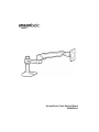
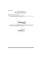
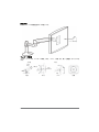
Amazon Basics Bras de support Simple à fixation User manual
- Category
- Flat panel desk mounts
- Type
- User manual
This manual is also suitable for

AmazonBasics Desk Monitor Mount
B00MIBN16O

2
English . . . . . . . . . . . . . . . . . . . . . .3
Français . . . . . . . . . . . . . . . . . . . .17
Deutsch . . . . . . . . . . . . . . . . . . . .31
日本語 . . . . . . . . . . 45
中文. . . . . . . . . . . . . . . . . . . . 59
Italiano . . . . . . . . . . . . . . . . . . . . .72
Español. . . . . . . . . . . . . . . . . . . . .86

3
English
Instruction Manual · English
AmazonBasics Desk Monitor Mount
Contents
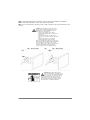
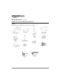
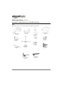
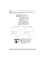
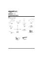
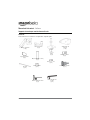
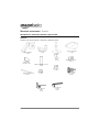
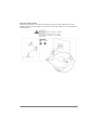
Make sure that the package contains the following parts:
Upper arm
(1 pc)
Bracket cover
(1 pc)
Grommet bracket
(1 pc)
M8 (1/4-20UNC, 3 inch)
(1 pc)
Wing nut
(1 pc)
Cable tie
(2 pcs)
M4 × 10 mm screw
(4 pcs)
Lower arm
(1 pc)
M4 × 10 mm knob
(4 pcs)
Base
(1 pc)
4 mm Allen wrench
(1 pc)
2.5 mm Allen wrench
(1 pc)
M3 x 6 mm
screw
1 (pc)

4
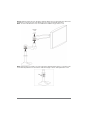
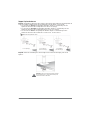
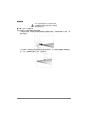
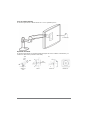
Supported monitor weights
Your monitor mount supports a monitor of the following weight:
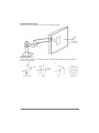
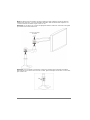
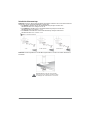
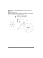
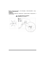
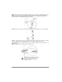
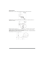
Monitor adjustments
Your monitor mount lets you adjust the monitor viewing angle, height, tilt, and orientation
(portrait or landscape).
5 to 25 lbs
(2.3 to 11.3 kg)
lbs
kg
360°
180°
360°
13 in.
(330 mm)
70°
5°
Viewing angle Height Tilt Orientation

5
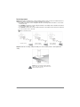
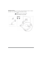
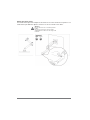
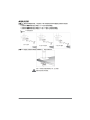
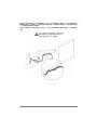
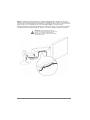
Assembly Instructions
Step 1: Choose a mounting option.
You can mount the monitor arm using the:
• Desk-clamp mount to attach your monitor arm to the edge of a tabletop. Go to
“Desk-clamp mount” on page 6.
• Plate mount to attach your monitor mount to an area that is away from the edge of a
tabletop. This mounting option requires a hole through the mounting surface. Go to
“Plate mount” on page 7.
Caution: Because mounting surface materials
can vary widely, make sure that the mounting
surface is strong enough to handle your monitor
mount and the monitor.

6
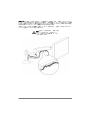
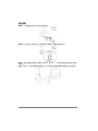
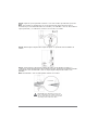
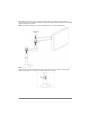
Desk-clamp mount
Step A: Determine the thickness of the mounting surface, then use the 4 mm Allen wrench to
adjust the location of the mounting clamp assembly, if necessary.
•The top screw holes on the clamp bracket fit a mounting surface thickness of less than
5/8 in. (1.6 cm).
•The middle screw holes on the clamp bracket fit a mounting surface thickness between
1/4 to 1 5/8 in. (0.6 to 4.1 cm).
•The bottom screw holes on the clamp bracket fit a mounting surface thickness between
1 1/4 to 2 5/8 in (3.2 to 6.7 cm).
Step B: Slide the mounting clamp assembly onto the mounting surface, then tighten the
clamp.
Caution: Do not rotate the monitor past the
edge of desk. The weight of the monitor may
cause the desk to tip over.
<3/8 in. (1 cm)
1/2 to 1-3/8 in.
(1.2 to 3.56 cm)
1.5 to 2-3/8 in.
(3.7 to 6.0 cm)
4 mm Allen wrench

7
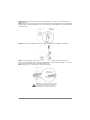
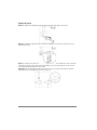
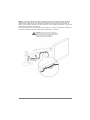
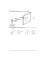
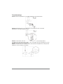
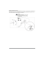
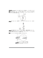
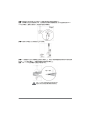
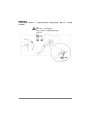
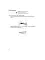
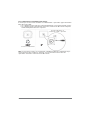
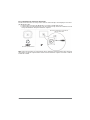
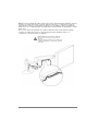
Plate mount
Step A: Remove the mounting clamp assembly from the clamp bracket on the base.
Step B: Remove the clamp bracket from the base. Keep the screws you remove. You will use
them later.
Step C: Make sure that the side of the grommet bracket with recessed screw holes is facing
down. Insert the M8 × 3 in. screw through the square hole in the center of the grommet
bracket.
Note: To keep the 3-inch screw from falling inside the base, temporarily attach the wing nut to
hold it in place.
4 mm
4 mm

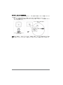
8
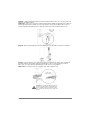
Step D: Attach the grommet bracket to the base with the 3 screws you removed from the
clamp bracket.
Note: If the screws are not flush to the grommet bracket, the grommet bracket is upside down.
Remove these screws and the M8 × 3 in. screw, turn the grommet bracket over, then put all the
screws back in.
Step E: Remove the clamp plate from the clamp assembly using a Phillips screwdriver.
Step F: Center the base over the top of the hole in the mounting surface, then, from the
bottom of the mounting surface, slide the clamp plate you removed onto the M8 × 3 in. screw.
Secure the clamp plate to the screw with the wing nut.
Note: The M8 × 3 in. screw must be centered in the hole.
Caution: For secure arm attachment and to
avoid equipment damage, the base and the
clamp plate must make contact with the
mounting surface on both sides of the hole.
4 mm
0.31 to 2 in.
(8 to 51 mm)
< 2.25 in.
(57 mm)

9
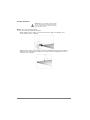
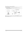
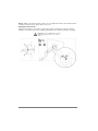
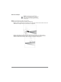
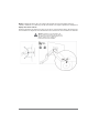
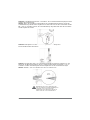
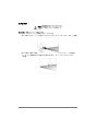
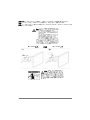
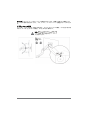
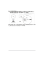
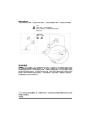
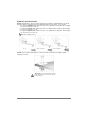
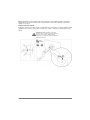
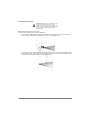
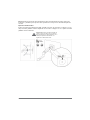
Step 2: Determine the orientation of the monitor
You can mount the monitor in a locked portrait or landscape orientation, or you can leave the
monitor free to rotate 360°.
• If you want the monitor to rotate freely, do not insert the M3 x 6 mm screw.
• If you want the monitor in a locked orientation, insert the M3 x 6 mm screw into the front
of the plate on the upper arm.
Note: If you insert the screw, then want to change the monitor’s orientation after you mount the
monitor to the upper arm, you need to remove the monitor from the upper arm and insert or
remove the M3 x 6 mm screw.
Monitor rotates freely.
Monitor is locked in portrait or
landscape orienation.

10
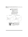
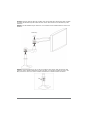
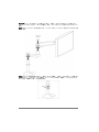
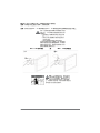
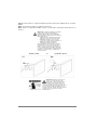
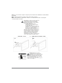
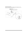
Step 3: Attach the upper arm to the back of the monitor using a Phillips screwdriver.
Note: If a stand is attached to the monitor, remove the stand.
Note: You can use the M4 × 10 mm screws or M4 × 10 mm knobs to attach the arm to the
monitor.
Caution: The mounting screw holes on the
back of the monitor may require screws of a
different type or length than the provided
M4 × 10 mm screws or knobs.
• Using screws of that are too big in
diameter will damage the screw holes on
the monitor.
• Using screws that are too small or too
short may cause the monitor to fall off the
arm.
• Using screws that are too long may
damage the interior of the monitor.
Before you attach the monitor to the upper arm,
make sure that the provided screws or knobs fit
the screw holes on the back of the monitor.
If the provided screws or knobs do not fit, refer
to the documentation that came with the
monitor for the correct screw type and size.
Warning: The upper arm is under
tension and will move up rapidly, on its
own, as soon as the attached monitor is
removed. For this reason, remove the upper
arm, lay the monitor face down on a soft
surface, then remove the monitor. Failure to
follow this instruction may result in serious
personal injury or equipment damage.
M4 × 10 mm screws M4 × 10 mm knobsOR

11
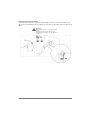
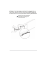
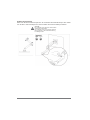
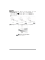
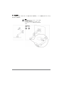
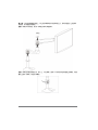
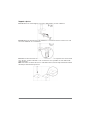
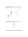
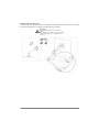
Step 4: Slide the lower arm onto the base. Slide the upper arm over the lower arm, then insert
the bracket cover into the top of the upper arm. The cover should snap into place.
Note: To remove the bracket cover, use a flathead screwdriver to pry off the cover.
Note: If the monitor is too high or too low, remove the upper and lower arms. Loosen the screw
on the base ring with the 2.5 mm wrench, slide the ring up or down, then tighten the screw.
Bracket
cover

12
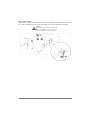
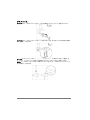
Step 5: Insert the cable ties through the loops on the bottom of the upper arm, route the
monitor cables along the upper arm, then loosely secure the cables to the upper arm with the
cable ties. Do not over-tighten the ties. If the ties are too tight and you try to remove them, you
may damage the monitor cables.
Squeeze the tabs on the lower arm cover to remove the cover, route the monitor cables along
the bottom of the lower arm, then replace the covers.
Caution: Before you tighten the cable ties,
adjust your monitor to the highest position. This
will leave enough slack in the cables for monitor
movement/height adjustment.
L
o
w
e
r
a
r
m
c
o
v
e
r
C
a
b
l
e
t
i
e
s

13
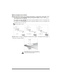
Step 6: Adjust your monitor mount's tension. You can adjust the vertical, tilt, and arm tension
so that the monitor stays in place when you move it.
Adjusting the vertical tension
Tilt the monitor down to access the screw. If the monitor is rising up, loosen the screw by
turning it to the left. If the monitor is falling down, tighten the screw by turning it to the right.
Caution: Do not over-tighten the screw. You
might damage the monitor or your monitor
mount.
4 mm

14
Adjusting the tilt tension
If the monitor is falling forward (screen goes down), loosen the screw by turning it to the left. If
the monitor is falling back (screen goes up), tighten the screw by turning it to the right.
Caution:
Do not remove the screw. The monitor might
fall.
Do not over-tighten the screw. You might
damage the monitor or your monitor mount.
4 mm

15
Adjusting the arm tension
To make the arm easier to move, loosen the screws by turning them to the left. To make the
arm harder to move, tighten the screws by turning them to the right.
Caution:
Do not remove the screws. The monitor might
fall.
Do not over-tighten the screws. You might
damage the monitor or your monitor mount.
2.5 mm

16
Safety and Compliance
IMPORTANT: This product will need tension adjustments after installation is complete. Make
sure that all equipment is properly installed on the product before attempting range of motion
or tension adjustments. Any time equipment is added or changed on this product resulting in a
different mounted weight, you should repeat the adjustment steps to ensure safe and optimum
operation. This product should move smoothly and easily through the full range of motion and
stay where you set it. If movement is difficult or the product does not stay where you set it,
follow the adjustment instructions to loosen or tighten the tension to create a smooth, easy
motion. Depending on your product and the adjustment, it may take many turns to notice a
difference.
© 2014 Amazon.com, Inc. or its affiliates. All Rights reserved. Amazon and the AmazonBasics logo are trademarks of Amazon.com, Inc. or its
affiliates.
Made in China
Page is loading ...
Page is loading ...
Page is loading ...
Page is loading ...
Page is loading ...
Page is loading ...
Page is loading ...
Page is loading ...
Page is loading ...
Page is loading ...
Page is loading ...
Page is loading ...
Page is loading ...
Page is loading ...
Page is loading ...
Page is loading ...
Page is loading ...
Page is loading ...
Page is loading ...
Page is loading ...
Page is loading ...
Page is loading ...
Page is loading ...
Page is loading ...
Page is loading ...
Page is loading ...
Page is loading ...
Page is loading ...
Page is loading ...
Page is loading ...
Page is loading ...
Page is loading ...
Page is loading ...
Page is loading ...
Page is loading ...
Page is loading ...
Page is loading ...
Page is loading ...
Page is loading ...
Page is loading ...
Page is loading ...
Page is loading ...
Page is loading ...
Page is loading ...
Page is loading ...
Page is loading ...
Page is loading ...
Page is loading ...
Page is loading ...
Page is loading ...
Page is loading ...
Page is loading ...
Page is loading ...
Page is loading ...
Page is loading ...
Page is loading ...
Page is loading ...
Page is loading ...
Page is loading ...
Page is loading ...
Page is loading ...
Page is loading ...
Page is loading ...
Page is loading ...
Page is loading ...
Page is loading ...
Page is loading ...
Page is loading ...
Page is loading ...
Page is loading ...
Page is loading ...
Page is loading ...
Page is loading ...
Page is loading ...
Page is loading ...
Page is loading ...
Page is loading ...
Page is loading ...
Page is loading ...
Page is loading ...
Page is loading ...
Page is loading ...
Page is loading ...

V2 14-1435
Made in China
-
 1
1
-
 2
2
-
 3
3
-
 4
4
-
 5
5
-
 6
6
-
 7
7
-
 8
8
-
 9
9
-
 10
10
-
 11
11
-
 12
12
-
 13
13
-
 14
14
-
 15
15
-
 16
16
-
 17
17
-
 18
18
-
 19
19
-
 20
20
-
 21
21
-
 22
22
-
 23
23
-
 24
24
-
 25
25
-
 26
26
-
 27
27
-
 28
28
-
 29
29
-
 30
30
-
 31
31
-
 32
32
-
 33
33
-
 34
34
-
 35
35
-
 36
36
-
 37
37
-
 38
38
-
 39
39
-
 40
40
-
 41
41
-
 42
42
-
 43
43
-
 44
44
-
 45
45
-
 46
46
-
 47
47
-
 48
48
-
 49
49
-
 50
50
-
 51
51
-
 52
52
-
 53
53
-
 54
54
-
 55
55
-
 56
56
-
 57
57
-
 58
58
-
 59
59
-
 60
60
-
 61
61
-
 62
62
-
 63
63
-
 64
64
-
 65
65
-
 66
66
-
 67
67
-
 68
68
-
 69
69
-
 70
70
-
 71
71
-
 72
72
-
 73
73
-
 74
74
-
 75
75
-
 76
76
-
 77
77
-
 78
78
-
 79
79
-
 80
80
-
 81
81
-
 82
82
-
 83
83
-
 84
84
-
 85
85
-
 86
86
-
 87
87
-
 88
88
-
 89
89
-
 90
90
-
 91
91
-
 92
92
-
 93
93
-
 94
94
-
 95
95
-
 96
96
-
 97
97
-
 98
98
-
 99
99
-
 100
100


Amazon Basics Bras de support Simple à fixation User manual
- Category
- Flat panel desk mounts
- Type
- User manual
- This manual is also suitable for
Ask a question and I''ll find the answer in the document
Finding information in a document is now easier with AI
in other languages
- italiano: Amazon Basics Bras de support Simple à fixation Manuale utente
- français: Amazon Basics Bras de support Simple à fixation Manuel utilisateur
- español: Amazon Basics Bras de support Simple à fixation Manual de usuario
- Deutsch: Amazon Basics Bras de support Simple à fixation Benutzerhandbuch
- 日本語: Amazon Basics Bras de support Simple à fixation ユーザーマニュアル


