Axis Communications M12 User manual
- Category
- Security cameras
- Type
- User manual
This manual is also suitable for

ENGLISH
FRANCAIS
DEUTSCH
ESPAÑOL
ITALIANO
AXIS 209FD/FD-R/FD-R M12
AXIS 209MFD/MFD-R/MFD-R M12
Installation Guide
Page is loading ...

AXIS 209FD/FD-R/FD-R M12/MFD/MFD-R/MFD-R M12 Installation Guide Page 3
ENGLISH
ENGLISH
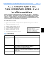
AXIS 209FD/FD-R/FD-R M12
AXIS 209MFD/MFD-R/MFD-R M12
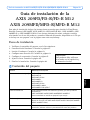
Installation Guide
This installation guide provides instructions for installing the AXIS 209FD, AXIS 209FD-R,
AXIS 209FD-R M12, AXIS 209MFD, AXIS 209MFD-R and the AXIS 209MFD-R M12 on
your network. For all other aspects of using the product, please see the User’s Manual,
available on the CD included in this package, or from www.axis.com/techsup
Installation steps
1. Check the package contents against the list below.
2. Hardware overview. See page 4.
3. Install the hardware. See page 5.
4. Set an IP address. See page 7.
5. Set the password. See page 10.
6. Adjust the lens. See page 11.
7. Complete the installation. See page 12.
Package contents
Item Models/variants/notes
Fixed Dome Network camera AXIS 209FD
AXIS 209FD-R
AXIS 209FD-R M12
AXIS 209MFD
AXIS 209MFD 16MM
AXIS 209MFD-R
AXIS 209MFD-R M12
AXIS 209MFD-R M12/SPLIT
PoE Midspan Power over Ethernet midspan (1 port), including mains cable
(AXIS 209FD/AXIS 209FD-R/AXIS 209MFD/AXIS 209MFD-R)
(midspan not included in bulk pack)
Mounting kit Allen key (hex key) for tamper-proof cover screws
Silica gel sachet (AXIS 209FD-R/AXIS 209FD-R M12/AXIS 209MFD-R/AXIS
209MFD-R M12 only)
CD AXIS Network Video Product CD, including product documentation,
installation tools and other software
Printed Materials AXIS 209FD/FD-R/FD-R M12/MFD/MFD-R/MFD-R M12 Installation Guide (this
document)
Axis Warranty Document
Important!
This product must be used in
compliance with local laws
and regulations.

Page 4 AXIS 209FD/FD-R/FD-R M12/MFD/MFD-R/MFD-R M12 Installation Guide
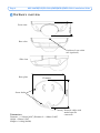
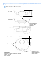
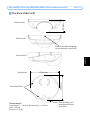
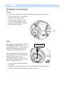
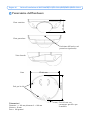
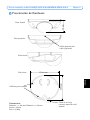
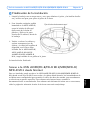
Hardware overview
Dimensions
Diameter 1 = 102mm (4.02”), Diameter 2 = 100mm (3.94”)
Height = 39mm (1.54”)
Weight = 0.18 kg (0.40lb)
Front view
Rear view
Side view
Position of rear cable
exit (optional)
Base plate
Network cable with
model-specific
connector
Screw holes
∅102mm
∅100mm
39mm

AXIS 209FD/FD-R/FD-R M12/MFD/MFD-R/MFD-R M12 Installation Guide Page 5
ENGLISH
ENGLISH
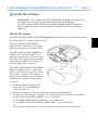
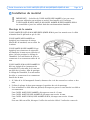
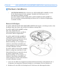
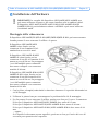
Install the hardware
Mount the camera
The AXIS 209FD/FD-R/FD-R M12/MFD/MFD-R/MFD-R M12 can be mounted with the cable
routed through the ceiling or from the side.
The AXIS 209FD/AXIS 209MFD is
supplied with a standard RJ-45 female
network connector, on a 2 meter cable.
The AXIS 209FD-R/AXIS 209MFD-R is
supplied with a 29mm female RJ-45
network connector on a 0.5 meter cable.
To protect the cabling against moisture
this connecter must be connected to a
suitable 29mm male connector.
The AXIS 209FD-R M12/AXIS 209MFD-
R M12 is supplied with a 21mm male
M12 D-code network connector on a 0.5
meter cable. To protect the cabling
against moisture this connecter must be
connected to a suitable 21mm female
connector.
1. Using the supplied allen/hex key,
loosen the 4 screws holding the
cover and remove it.
2. Use the base plate to mark out the positions for the mounting screws.
3. To route the cable through a ceiling, cut or drill the hole for the cable and connector.
For the AXIS 209FD/AXIS 209MFD - cut a 17mm hole.
For the AXIS 209FD-R/AXIS 209MFD-R - cut a 30mm hole.
For the AXIS 209FD-R M12/AXIS 209MFD-R M12 - cut a 22mm hole.
-or-
For a surface mounted cable, cut out the cable exit hole at the rear of the cover
!
IMPORTANT! - The casing of the AXIS 209FD/AXIS 209MFD is not approved
for outdoor use and may only be installed in indoor environments.
The AXIS 209FD-R/AXIS 209FD-R M12/AXIS 209MFD-R/AXIS 209MFD-R
M12 is rugged and can be used in humid environments such as mass transit
vehicles.

Page 6 AXIS 209FD/FD-R/FD-R M12/MFD/MFD-R/MFD-R M12 Installation Guide
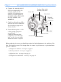
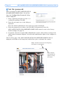
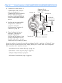
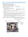
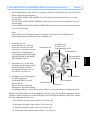
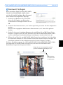
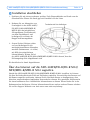
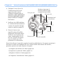
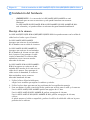
4. Connect the network cable. If
PoE is not supported by the
network switch, use the
supplied PoE midspan/power
injector to connect power to
the AXIS 209FD, AXIS 209FD-
R, AXIS 209MFD, AXIS
209MFD-R.
5. Check that the indicator LED:s
indicate the correct conditions.
See the table on page 14 for
further details.
6. Fasten the base plate to a flat
ceiling, using appropriate
screws/plugs.
Check that the base plate
completely covers the cable
hole, so that it is not visible
when the camera is in place.
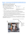
Before replacing the cover, you should now make the final adjustment to the position of the
lens. This requires access to live images from the camera in your browser, so you should now
proceed as follows:
a) Assign an IP address - see step 4 on page 7.
b) Set the password - see step 5 on page 10.
c) Adjust the lens - see step 6 on page 11.
d) Complete the installation - see step 7 on page 12.
Network
cable with
connector
Indicator LEDs
Screw hole
Screw hole
Screw hole
Product ID & Serial
number (S/N) label
Screw hole
Control button

AXIS 209FD/FD-R/FD-R M12/MFD/MFD-R/MFD-R M12 Installation Guide Page 7
ENGLISH
ENGLISH
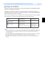
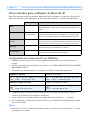
Assign an IP address
To make it accessible on the network, the AXIS 209FD/FD-R/FD-R M12/MFD/MFD-R/MFD-
R M12 must be assigned an IP address.
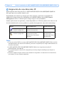
Depending on the number of cameras you wish to install, the recommended method for
assigning IP addresses in Windows is either AXIS IP Utility or AXIS Camera Management.
Use the method that best suits your purpose.
Both of these free applications are available on the Axis Network Video Product CD supplied
with this product, or they can be downloaded from www.axis.com/techsup
Notes:
• If there is a DHCP server on your network the AXIS 209FD/FD-R/FD-R M12/MFD/MFD-R/MFD-R M12
will automatically receive a dynamic IP address, but this will not prevent manual setting of an
alternative address.
• The AXIS 209FD/FD-R/FD-R M12/MFD/MFD-R/MFD-R M12 has the default IP address 192.168.0.90
• If assigning the IP address fails, check that there is no firewall blocking the operation.
• For other methods of assigning or discovering the IP address, e.g. in other operating systems, see
page 13.
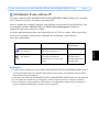
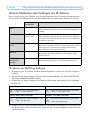
Method Recommended for Operating system
AXIS IP Utility
See page 8
Single camera
Small installations
Windows
AXIS Camera Management
See page 9
Multiple cameras
Large installations
Installation on a different subnet
Windows 2000
Windows XP Pro
Windows 2003 Server
Windows Vista

Page 8 AXIS 209FD/FD-R/FD-R M12/MFD/MFD-R/MFD-R M12 Installation Guide
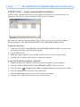
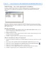
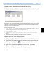
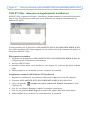
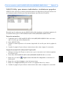
AXIS IP Utility - single camera/small installation
AXIS IP Utility automatically discovers and displays Axis devices on your network. The
application can also be used to manually assign a static IP address.
Note that the computer running AXIS IP Utility must be on the same network segment
(physical subnet) as the AXIS 209FD/FD-R/FD-R M12/MFD/MFD-R/MFD-R M12.
Automatic discovery
1. Check that the AXIS 209FD/FD-R/FD-R M12/MFD/MFD-R/MFD-R M12 is connected to
the network and that power has been applied.
2. Start AXIS IP Utility.
3. When the camera appears in the window, double-click it to open its home page.
4. See page 10 for instructions on how to assign the password.
Assign the IP address manually (optional)
1. Acquire an unused IP address on the same network segment as your computer.
2. Select the AXIS 209FD/FD-R/FD-R M12/MFD/MFD-R/MFD-R M12 in the list.
3. Click the button Assign new IP address to selected device and enter the IP address.
4. Click the Assign button and follow the instructions.
5. Click the Home Page button to access the camera’s web pages.
6. See page 10 for instructions on how to set the password.

AXIS 209FD/FD-R/FD-R M12/MFD/MFD-R/MFD-R M12 Installation Guide Page 9
ENGLISH
ENGLISH
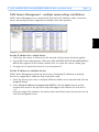
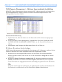
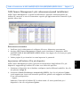
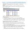
AXIS Camera Management - multiple cameras/large installations
AXIS Camera Management can automatically find and set IP addresses, show connection
status, and manage firmware upgrades for multiple Axis video products.
Set the IP address for a single device
1. Check that the camera is connected to the network and that power has been applied.
2. Start AXIS Camera Management. When the AXIS 209FD/FD-R/FD-R M12/MFD/MFD-R/
MFD-R M12 appears in the window, double-click it to open the camera’s home page.
3. See page 10 for instructions on how to set the password.
Set the IP address in multiple devices
AXIS Camera Management speeds up the process of assigning IP addresses to multiple
devices, by suggesting IP addresses from a specified range.
1. Select the devices you wish to configure (different models can be selected) and click the
Assign IP button.
2. Select Obtain IP addresses automatically (DHCP), click the Update button and the
program will search in the specified range and suggest an IP address for each device.
-or-
Enter the range of IP addresses, the subnet mask and default router that devices can use
and click the Update button.

Page 10 AXIS 209FD/FD-R/FD-R M12/MFD/MFD-R/MFD-R M12 Installation Guide
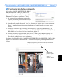
Set the password
When accessing the AXIS 209FD/FD-R/FD-R
M12/MFD/MFD-R/MFD-R M12 for the first
time, the ‘Configure Root Password’ dialog
will be displayed.
1. Enter a password and then re-enter it, to
confirm the spelling. Click OK.
2. Enter the user name root in the dialog as
requested.
Note: The default administrator user name root cannot be deleted.
3. Enter the password as set above, and click OK. If the password is lost, the
AXIS 209FD/FD-R/FD-R M12/MFD/MFD-R/MFD-R M12 must be reset to the factory
default settings. See page 14.
4. If required, click Yes to install AMC (AXIS Media Control), which allows viewing of the
video stream in Internet Explorer. You will need administrator rights on the computer to
do this.
The Live View page of the AXIS 209FD/FD-R/FD-R M12/MFD/MFD-R/MFD-R M12 is
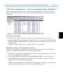
displayed, with links to the Setup tools, which allow you to customize the camera.
Setup - Provides all the tools for configuring
the camera to requirements.
Help - Displays
online help on all
aspects of using
the camera.

AXIS 209FD/FD-R/FD-R M12/MFD/MFD-R/MFD-R M12 Installation Guide Page 11
ENGLISH
ENGLISH
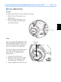
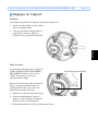
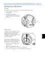
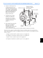
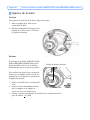
Lens adjustments
Position
To adjust the position of the lens, follow these steps:
1. Open the Live View page in your
web browser.
2. While checking the image in the
Live View page, move the lens to
the desired position.
Focus
The focus of the AXIS 209FD/FD-R/FD-
R M12/MFD/MFD-R/MFD-R M12 is set
at the factory from 0.5m to infinity. It
does not normally need adjustment.
To focus on objects closer than 0.5m, or
if for some reason the lens has lost
focus, this can be adjusted in the
following way.
1. Loosen the lens lock screw.
2. Manually rotate the lens to adjust
the focus until the image on the
Live View page is satisfactory.
3. Gently retighten the lens lock screw.
Lens lock
screw

Page 12 AXIS 209FD/FD-R/FD-R M12/MFD/MFD-R/MFD-R M12 Installation Guide
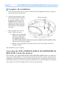
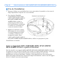
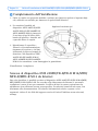
Complete the installation
1. Clean the dome with a dry soft cloth to remove dust and fingerprints and use a blower to
remove any dust from the lens.
2. To absorb any moisture in the
AXIS 209FD-R/AXIS 209FD-R
M12/AXIS 209MFD-R/AXIS
209MFD-R M12, remove the
supplied silica gel sachet (dry
bag) from the plastic bag and
affix inside the cover, behind
the dome.
3. You can replace the cover in
either of these two ways:
• Replace cover and gently
tighten the tamper-proof
screws by hand using
the supplied allen key. In
the AXIS 209FD-R/AXIS 209FD-R M12/AXIS 209MFD-R/AXIS 209MFD-R M12,
take care not to pinch the gasket.
• Replace cover and tighten the tamper-proof screws with torque screwdriver
(torque<0.4 Nm).
The installation is now complete.
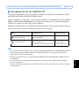
Accessing the AXIS 209FD/FD-R/FD-R M12/MFD/MFD-R/
MFD-R M12 from the Internet
Once installed, your AXIS 209FD/FD-R/FD-R M12/MFD/MFD-R/MFD-R M12 is accessible on
your local network (LAN). To access the camera from the Internet, network routers must be
configured to allow incoming traffic, which is usually done on a specific port. Please refer to
the documentation for your router for further instructions. For more information on this and
other topics, visit the Axis Support Web at www.axis.com/techsup
Affix dry bag here.

AXIS 209FD/FD-R/FD-R M12/MFD/MFD-R/MFD-R M12 Installation Guide Page 13
ENGLISH
ENGLISH
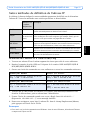
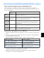
Other methods of setting the IP address
The table below shows the other methods available for setting or discovering the IP address.
All methods are enabled by default, and all can be disabled.
Set the IP address with ARP/Ping
1. Acquire an IP address on the same network segment your computer is connected to.
2. Locate the serial number (S/N) on the AXIS 209FD/FD-R/FD-R M12/MFD/MFD-R/MFD-R
M12 label.
3. Open a command prompt on your computer and enter the following commands:
4. Check that the network cable is connected to the camera and then start/restart the
camera, by disconnecting and reconnecting power.
5. Close the command prompt when you see ‘Reply from 192.168.0.125: ...’ or similar.
6. In your browser, type in http://<IP address> in the Location/Address field and press Enter
on your keyboard.
Notes:
• To open a command prompt in Windows: from the Start menu, select Run... and type cmd. Click OK.
• To use the ARP command on a Mac OS X, use the Terminal utility in Application > Utilities.
Use in operating
system
Notes
UPnP™
Windows When enabled on your computer, the camera is automatically
detected and added to “My Network Places.”
Bonjour
MAC OSX
(10.4 or later)
Applicable to browsers with support for Bonjour. Navigate to the
Bonjour bookmark in your browser (e.g. Safari) and click on the
link to access the camera’s web pages.
AXIS Dynamic DNS
Service
All A free service from Axis that allows you to quickly and simply
install your camera. Requires an Internet connection with no
HTTP proxy. See www.axiscam.net for more information.
ARP/Ping
All See below. The command must be issued within 2 minutes of
connecting power to the camera.
View DHCP server
admin pages
All To view the admin pages for the network DHCP server, see the
server’s own documentation.
Windows syntax Windows example
arp -s <IP Address> <Serial Number>
ping -l 408 -t <IP Address>
arp -s 192.168.0.125 00-40-8c-18-10-00
ping -l 408 -t 192.168.0.125
UNIX/Linux/Mac syntax UNIX/Linux/Mac example
arp -s <IP Address> <Serial Number> temp
ping -s 408 <IP Address>
arp -s 192.168.0.125 00:40:8c:18:10:00
temp
ping -s 408 192.168.0.125

Page 14 AXIS 209FD/FD-R/FD-R M12/MFD/MFD-R/MFD-R M12 Installation Guide
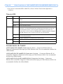
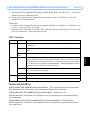
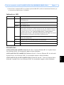
LED indicators
Unit connectors
(AXIS 209FD/AXIS 209MFD) Network connector - Female RJ-45 Ethernet connector for
10BaseT/100BaseTX. Supports Power over Ethernet. Using shielded cables is recommended.
(AXIS 209FD-R/AXIS 209MFD-R) Network connector - Rugged female RJ-45 connector.
Supports Power over Ethernet. Using shielded cables is recommended
(AXIS 209FD-R M12/AXIS 209MFD-R M12) Network connector - Rugged male M12
Ethernet connector. Supports Power over Ethernet. Using shielded cables is recommended.
LED Color Indication
Network Green Steady for connection to a 100 Mbit/s network. Flashes for network activity.
Amber Steady for connection to 10 Mbit/s network. Flashes for network activity.
Unlit No network connection.
Status Green Steady green for normal operation.
Note: The Status LED can be configured to be unlit during normal operation, or to
flash only when the camera is accessed. To configure, go to Setup > System
Options > LED settings. See the online help files for more information.
Amber Steady during startup, during reset to factory default or when restoring settings.
Red Slow flash for failed upgrade.
Power Green Normal operation.
Amber Flashes green/amber during firmware upgrade.

AXIS 209FD/FD-R/FD-R M12/MFD/MFD-R/MFD-R M12 Installation Guide Page 15
ENGLISH
ENGLISH
Resetting to the Factory Default Settings
This will reset all parameters, including the IP address, to the Factory Default settings:
1. Disconnect the network cable from the camera.
2. Using the supplied allen/hex key, loosen the 4 screws holding the cover and remove it.
3. Press and hold the Control button and reconnect the network cable.
4. Keep the Control button pressed until the Status indicator displays amber (this may take
up to 15 seconds).
5. Release the Control button. When the Status indicator displays green (which can take up
to 1 minute) the process is complete and the camera has been reset.
6. Re-assign the IP address, using one of the methods described in this document.
It is also possible to reset parameters to the original factory default settings via the web
interface. For more information, please see the online help or the user’s manual.
Further information
The user’s manual is available from the Axis Web site at www.axis.com or from the Axis
Network Video Product CD supplied with this product.
Tip!
Visit www.axis.com/techsup to check if there is updated firmware available for your
AXIS 209FD/FD-R/FD-R M12/MFD/MFD-R/MFD-R M12. To see the currently
installed firmware version, see the Basic Configuration web page in the product’s
Setup tools.

Page 16 AXIS 209FD/FD-R/FD-R M12/MFD/MFD-R/MFD-R M12 Installation Guide
Page is loading ...
Page is loading ...
Page is loading ...
Page is loading ...
Page is loading ...
Page is loading ...
Page is loading ...
Page is loading ...
Page is loading ...
Page is loading ...
Page is loading ...
Page is loading ...
Page is loading ...
Page is loading ...
Page is loading ...
Page is loading ...
Page is loading ...
Page is loading ...
Page is loading ...
Page is loading ...
Page is loading ...
Page is loading ...
Page is loading ...
Page is loading ...
Page is loading ...
Page is loading ...
Page is loading ...
Page is loading ...
Page is loading ...
Page is loading ...
Page is loading ...
Page is loading ...
Page is loading ...
Page is loading ...
Page is loading ...
Page is loading ...
Page is loading ...
Page is loading ...
Page is loading ...
Page is loading ...
Page is loading ...
Page is loading ...
Page is loading ...
Page is loading ...
Page is loading ...
Page is loading ...
Page is loading ...
Page is loading ...
Page is loading ...
Page is loading ...
Page is loading ...
Page is loading ...
Page is loading ...
Page is loading ...
Page is loading ...
Page is loading ...
Page is loading ...
Page is loading ...

AXIS 209FD/FD-R/FD-R M12/MFD/MFD-R/MFD-R M12 December 2008
Installation Guide v3.2
Copyright © Axis Communications AB, 2007 - 2008 Part No. 34066
-
 1
1
-
 2
2
-
 3
3
-
 4
4
-
 5
5
-
 6
6
-
 7
7
-
 8
8
-
 9
9
-
 10
10
-
 11
11
-
 12
12
-
 13
13
-
 14
14
-
 15
15
-
 16
16
-
 17
17
-
 18
18
-
 19
19
-
 20
20
-
 21
21
-
 22
22
-
 23
23
-
 24
24
-
 25
25
-
 26
26
-
 27
27
-
 28
28
-
 29
29
-
 30
30
-
 31
31
-
 32
32
-
 33
33
-
 34
34
-
 35
35
-
 36
36
-
 37
37
-
 38
38
-
 39
39
-
 40
40
-
 41
41
-
 42
42
-
 43
43
-
 44
44
-
 45
45
-
 46
46
-
 47
47
-
 48
48
-
 49
49
-
 50
50
-
 51
51
-
 52
52
-
 53
53
-
 54
54
-
 55
55
-
 56
56
-
 57
57
-
 58
58
-
 59
59
-
 60
60
-
 61
61
-
 62
62
-
 63
63
-
 64
64
-
 65
65
-
 66
66
-
 67
67
-
 68
68
-
 69
69
-
 70
70
-
 71
71
-
 72
72
-
 73
73
-
 74
74
-
 75
75


Axis Communications M12 User manual
- Category
- Security cameras
- Type
- User manual
- This manual is also suitable for
Ask a question and I''ll find the answer in the document
Finding information in a document is now easier with AI
in other languages
- italiano: Axis Communications M12 Manuale utente
- français: Axis Communications M12 Manuel utilisateur
- español: Axis Communications M12 Manual de usuario
- Deutsch: Axis Communications M12 Benutzerhandbuch
Related papers
-
Axis Communications 209FD-R User manual
-
-
-
-
Axis Communications 5504-971 User manual
-
Axis Communications P5512-E PTZ Installation guide
-
-
-
Axis Communications M7010 User manual
-
Other documents
-
Axis 0286-006 Datasheet
-
Axis Q1910 Thermal Network Camera Installation guide
-
Axis M1011-W Network Camera, 10-pack/bulk Installation guide
-
Axis AXIS 209MFD-R User manual
-
Axis 209FD User manual
-
-
Axis Q1604 Installation guide
-
-
-
AUKEY PL-WD07 User manual