
Quick Start Guide
NXD & NXT-1200V
Modero Video Touch Panel (G4)
For more detailed installation, configuration, programming, file transfer, and
operating instructions, refer to the 1200V-Series Modero Touch Panels
Instruction Manual available on-line at www.amx.com.
ATTENTION!
Verify you are using the latest NetLinx Master and Modero touch panel firmware
(available from www.amx.com). Verify the TPDesign4 program being used is
Version 2.6 or higher.
Overview
The new 12" Modero Touch Panels (NXT/NXD-1200V) feature dual USB
connectivity for mouse and keyboard, as well as Composite/S-Video support.
The following is a listing of the currently available 1200V panels:
• NXD-1200V (FG2251-60K) - 12" Modero Video WallMount touch
panel Kit
• NXT-1200V (FG2250-60K) - 12" Modero Video Table Top touch
panel Kit
Specifications
Panel Connectors
FIG. 2 shows the connectors located on the 1200V Modero Video panels. The
Audio/Video RJ-45 connector provides differential audio/video signals between
the touch panel and the NXA-AVB/ETHERNET. This connector routes
Composite video, Stereo (left/right) audio, and microphone audio.
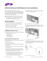
NXA-AVB/ETHERNET Breakout Box
FIG. 3 shows the front and rear connectors on the NXA-AVB/ETHERNET
breakout box. This breakout box can be mounted on either a horizontal flat
surface or in an equipment rack (by removing the front faceplate and securing it
to an (optional) AC-RK Rack Kit).
FIG. 1 Sample Wall Mount and Table Top 1200V Touch Panels
1200V Specifications
Dimensions (HWD): • NXD-1200V (with faceplate): 12.38" x 12.59" x 3.25"
(31.43 cm x 31.97 cm x 8.25 cm)
• NXT-1200V (Fully raised): 10.91" x 12.34" x 12.50"
(27.70 cm x 31.33 cm x 31.75 cm)
• NXT-1200V (Fully lowered): 6.77" x 12.34" x 12.50"
(17.20 cm x 31.33 cm x 31.75 cm)
• CB-TP12 (conduit/wallbox): 11.52" x 11.60" x 3.50"
(29.27 cm x 29.47 cm x 8.89 cm)
• MB-TP12 (VESA mounting box): 12.37" x 12.58" x 3.52"
(31.42 cm x 31.95 cm x 8.94 cm)
Power: • Constant current draw: 2.1 A @ 12 VDC (stand-alone)
• Startup current draw: 3.2 A @ 12 VDC (stand-alone)
Minimum power
supply required:
• PSN4.4 Power Supply (FG423-45)
- using accessories can increase the power draw requirements.
Memory: • 256 MB on-board memory
• 128 MB Compact Flash (upgradeable to 1 GB factory programmed)
Weight: • NXD-1200V: 10.80 lbs (4.90 kg)
• NXT-1200V: 10.80 lbs (4.90 kg)
LCD Parameters: • Aspect Ratio: 4:3
• Brightness (luminance): 250 cd/m2
• Channel transparency: 8-bit Alpha channel transparency
• Contrast ratio: 300:1
• Display area (HW): 183.10 mm x 247.40 mm
• Display colors: 256K (18-bit color depth)
• Dot/Pixel pitch: 0.297 mm
• Screen resolution (HV): 800 x 600 pixels
• Video formats: NTSC, PAL, and SECAM
(shown within variable-size video windows)
Viewing Angles: • Vertical: + 80° (up from center) and - 80° (down from center)
Supported Audio
Sample Rates:
• 48000Hz, 44100Hz, 32000Hz, 24000Hz, 22050Hz, 16000Hz,
12000Hz, 11025Hz, and 8000Hz.
Certifications: • FCC Part 15 Class B, CE, and EN 60950
Front Panel
Components:
• Light Sensor: Photosensitive light detector for automatic adjustment of
the panel brightness
• Motion Sensor (PIR): Proximity Infrared Detector to wake the panel
when panel is approached
• Front Setup Access Button: Pushbutton (grey) used to either put the
panel into a "sleep" or "wake" state
• Microphone: Used for intercom applications
• Speakers: Stereo output with a frequency response of 450 Hz - 7 KHz
NXD-1200V
NXT-1200V
(Wall Mount)
(Table Top)
1200V Specifications (Cont.)
Rear Panel
Components:
• Audio/Video Connector: RJ-45 connector for communication of
differential audio/video signals
• Ethernet 10/100 Port: RJ-45 port for 10/100 Mbps communication
• PWR Connector: 2-pin 3.5 mm mini-Phoenix connector
• Stereo Output Connector: Stereo output through a 3.5mm mini-jack
• USB Connector: Two Type A USB ports
• Mini-USB Connector: 5-pin Mini-USB connector
Operating /Storage
Environments:
• Operating Temperature: 10° C (50° F) to 40° C (104° F)
• Operating Humidity: 20% to 85% RH
• Storage Temperature: -20° C (-4° F) to 60° C (140° F)
• Storage Humidity: 5% to 85% RH
Included
Accessories:
• Installation Kit for 12" and 17" NXD panels (KA2251-01):
- 2-pin mini-Phoenix connector (41-5025)
- Three Phillips-head screws (#4-20 x 0.250 Black) (80-0114-08)
- One CAT5 Suppression Ferrites (04-0014)
- Four Drywall clips (62-5924-05) and #6 -metal strips (80-0192)
• Installation Kit for 12" NXT panels (KA2251-03):
- 2-pin mini-Phoenix connector (41-5025)
- Three Phillips-head screws (#4-20 x 0.250 Black) (80-0114-08)
- Two CAT5 Suppression Ferrites (04-0014)
• Modero Table Top Cable (CA2250-50)
- provided with all NXT Table Top panels.
• NXA-AVB/ETHERNET Breakout Box (FG2254-10)
Other AMX
Equipment:
• CB-TP12 Conduit/Wallbox (FG031-10)
• CC-USB (Type A) to Mini-B 5-Wire programming cable (FG10-5965)
• Kensington Lock Bracket (FG2259-10) (optional only with NXTs)
• MB-TP12 Universal VESA Mounting Box for NXD panels (FG031-50):
- Black metallic VESA back box (62-0031-50)
- Black plastic cover (with grommet opening) (60-0031-50)
- Strain relief grommet (45-0004-03)
- Four Phillips pan-head screws (#8-32 x 0.50 Black) (80-0146-02)
- Twelve Under-cut Phillips-head screws (#6-32 x 0.500 Black)
(80-0139)
• NXA-BASE/B (FG2255)
• NXA-PCI80211G Wireless Card (FG2255-04)
• NXA-RK12 Rackmount kit for 12" Wall Mount panels (FG2904-50)
• NXT-BP (FG2250-10)
• NXT-CHG (FG2250-50)
• PSN4.4 Power Supply (12 VDC) (FG423-45)
• PSN6.5 Power Supply (12 VDC) (FG423-41)
• Upgrade Compact Flash (factory programmed with firmware):
NXA-CFTPV256M - 256 MB V/VG compact flash card (FG2116-43)
NXA-CFTPV512M - 512 MB V/VG compact flash card (FG2116-44)
NXA-CFTPV1G - 1 GB V/VG compact flash card (FG2116-45)
FIG. 2 Connector layout on the 1200V Touch Panels
FIG. 3 Connector layouts on the NXA-AVB/ETHERNET Breakout Box
A
PWR
12VDC
L
ETHERNETAUDIO/VIDEO
PROGRAM
Stereo
Audio-Video from
Ethernet
Power
NXA-AVB/ETHERNET
(CAT5)
Keyboard/Mouse
USB connectors (2)
Mini-USB
(Program Port)
(CAT5)
Output
Power In
(front)
Ethernet (to panel)
Audio/Video
Power (to panel)
S-Video Chroma
Composite/
Mic Out
Audio
In
Ethernet In
S-Video
Luma
(rear)
(to panel)

For full warranty information, refer to the AMX Instruction Manual(s) associated with your Product(s).
11/07
©2007 AMX. All rights reserved. AMX and the AMX logo are registered trademarks of AMX.
AMX reserves the right to alter specifications without notice at any time.
3000 RESEARCH DRIVE, RICHARDSON, TX 75082 • 800.222.0193 • fax 469.624.7153 • technical support 800.932.6993 • www.amx.com
93-2251-60 REV: D
Wiring the NXA-AVB/ETHERNET Connectors and Cables
The inputs and outputs on the breakout box are separated into front and rear
connectors. The rear connectors are used to input external signals. The front
connectors are used to communicate signals between the
NXA-AVB/ETHERNET and a target Modero panel. FIG. 4 provides a layout of
the wiring connection both into and from the breakout box. Power should be
applied to the NXA-AVB/ETHERNET only after all connections have been
secured onto both the breakout box and the target panel.
Use a standard CAT5 Ethernet cable (connected to the rear of the Table Top
Panel or to the side of the Wall Panel) to provide both communication and
10/100 network connectivity between the panel, breakout box, NetLinx Master,
and the network. The rear-panel wiring connections are described below (from
left to right):
Wiring for Unbalanced Audio
Use FIG. 5 to configure an unbalanced audio connection.
Wiring for Balanced Audio
Use FIG. 6 to configure a balanced audio connection.
Modero Setup and System Connection
1. Carefully remove the panel from the shipping box, peel the protective
plastic cover from the LCD and apply power to the panel.
2. From below the LCD, press the grey Front Setup Access button for
6 seconds (passing-over the Setup page) to access the Calibration setup
page and follow the on-screen instructions.
3. Press the grey Firmware Setup Access button for 3 seconds to open the
Setup page and touch the on-screen Protected Setup button.
4. Enter the panel password into the keypad (default is 1988).
5. Press the Device Number field to open the on-screen Device
Number keypad and enter a value for the panel (default is 10001).
6. Press Done when finished and press the on-screen Reboot button to
cycle power to the panel.
7. Repeat step 3 to access the Protected Setup page and touch the System
Settings button to open the System Settings page (
FIG. 7).
8. Toggle the Type field to Ethernet.
9. Enter both the System Number and IP Address of the target Master.
10. Enter a valid Username and/or Password if the target Master is secured.
11. Press the Back button and then press the on-screen Reboot button to
save the changes and cycle power.
FIG. 4 NXA-AVB/ETHERNET Breakout Box connector wiring diagram
AUDIO IN: 6-pin mini-Phoenix connector, divided into left and right audio chan-
nels. Each channel is divided into GND, IN+, and IN- terminal cable
connectors (2 sets of 3 for each channel).
MIC OUT: 4-pin mini-Phoenix connector, divided into GND, OUT-, and OUT+
terminal connectors.
Video In BNCs: Feeds either Composite/S-Video Luma or S-Video Chroma signals
into the NXA-AVB/ETHERNET. This feed is then redirected out to a
Modero panel through the front
Audio/Video CAT5 port.
ETHERNET: RJ-45 connector routes data to the G4 touch panel through the front
Ethernet port. These connections use a standard CAT5 Ethernet
cable to provide communication between the target touch panel,
Breakout Box, and NetLinx Master.
PWR 2-pin mini-Phoenix connector that connects to a PSN power supply.
This port can be used to provide power to a Modero panel by sending
it through the
NXA-AVB/ETHERNET (rear power connector through to the front
power connector).
FIG. 5 Wiring the rear AUDIO IN and MIC OUT for use with Unbalanced Audio
NXA-AVB/ETHERNET
Breakout Box
Ethernet
(RJ-45)
Comp/Y (BNC)
C (BNC)
Audio In -
Left Channel
(6-pin captive wire)
Audio In -
Right Channel
(6-pin captive wire)
GND
In (-)
In (+)
GND
In (-)
In (+)
GND(-)
Out (-)
Out (+)
Microphone Out
(4-pin captive wire)
Power
Ethernet Out
(CAT5)
Audio/Video
(CAT5)
Power to
touch panel
F
R
O
N
T
R
E
A
R
supply
Unbalanced
IN
GND
IN-
IN+
GND
IN-
IN+
Left Channel
Right Channel
(Jumper IN- to GND)
Unbalanced
OUT
GND
OUT-
OUT+
Microphone
Unbalanced
IN
(Jumper IN- to GND)
AUDIO IN
MIC OUT
FIG. 6 Wiring the rear AUDIO IN and MIC OUT for use with Balanced Audio
FIG. 7 Sample System Settings page
Balanced OUT
GND
OUT-
OUT+
Ground signal
Return signal
Line signal
Panel’s connection information
Master’s
connection
information
-
 1
1
-
 2
2


AMX Modero Video Touch Panel (G4) NXT/NXD-1200V Quick start guide
- Type
- Quick start guide
- This manual is also suitable for
Ask a question and I''ll find the answer in the document
Finding information in a document is now easier with AI
Related papers
-
AMX NXA-AVB/ETHERNET Operating instructions
-
AMX NXD-1200V User manual
-
-
AMX NXA-AVB/RGB Quick start guide
-
AMX NXT-1200VG Specification
-
-
-
-
-
Other documents
-
 Cables Direct UT-899002 Datasheet
-
 Cables Direct UT-899001 Datasheet
-
Lego Mindstorms NXT 2.0 User manual
-
Kramer Electronics C-SM/2BF-1 Datasheet
-
Kramer Electronics C-SM/2BM-10 Datasheet
-
American Range AVCB-2 Datasheet
-
TOA SR-TP12 Specification Data
-
 AVB AVB-192 Installation guide
-
Intermec CV30 Operating instructions
-
Yamaha Example Programs (AMX) - Setup Guide Installation guide


