
January 2003
______________________________________________________________________
______________________________________________________________________
1
AMCO Water Metering Systems For Potable Cold Water Meters
Installation/Start-up Instructions
INTRODUCTION
All AMCO water meters have been manufactured with current technology in
accordance with applicable AWWA standards. Water passes through a measuring
chamber driving an oscillating piston or rotor, the movements of which are transferred
by appropriate gearing and magnetic drive to a standard direct reading sealed register.
If the meter has been ordered with visual remote (RMR), electronic remote (EMR) or
InsideR™ transmitter, refer to the following documents for additional instructions:
1. Remote Meter Read (RMR) RMR-INS-022
2. Encoder Electronic Meter Read (EMR) EMR-INS-026
3. InsideR™ INS-INSIDE-RF
TESTING FOR METER ACCURACY
All AMCO water meters have been flow tested before shipment. Should further
accuracy tests be necessary, the requirements of Table 5-3 of the AWWA Manual M-6
should be followed. Before testing, thoroughly flush the meter to eliminate all air from
the test bench system. In the case of turbine and compound meters, water should
pass through as much straight pipe as possible before entering the meter, or install a
turbulence canceling strainer ahead of the meter. Turbines and compound meters
tested in series must have straight pipe between meters for absolute accuracy testing.
GENERAL INSTALLATION INSTRUCTIONS FOR ALL AMCO WATER METERS
(1) Install meters in a service line which has been flushed free of foreign
material.
(2) Install meters in horizontal or inclined pipe work.
(3) Install meters with the flow direction arrow pointing downstream, i.e. towards
the utility customer’s facility being served by the meter.
(4) Thoroughly tighten all meter couplings or companion flange bolts.
POSITIVE DISPLACEMENT AND TURBINE METER START-UP
A meter’s measuring device can be damaged if subjected to full flow conditions prior to
expelling all the air from the pipeline.
(5) With all valves closed, open a downstream faucet or other fixture that will
demand water from the water main.

MTR-INS-018/01-03 January 2003
2
(6) Gradually open the upstream valve to allow water to pass through the meter.
(7) Observe that the register’s sweep hand is turning clockwise in response to
the water throughput.
(8) Observe that the lowest value totalizer wheel advances one (1) number for
each complete turn of the sweep hand.
(9) When all the air has been expelled from the pipeline, close the downstream
faucet or fixture.
(10) Check all connections to detect leaks.
(11) Observe the low flow detector to identify downstream piping leaks.
COMPOUND METER START-UP
At start-up, the changeover valve is closed, diverting water through the bypass meter.
When 6.5 psi differential exists across the valve, with at least 13 psi pressure
downstream, the valve will open allowing water flow through the main line turbine
meter; however, water will continue to be measured by the bypass meter.
(12) With all valves closed, open slightly a downstream faucet or other fixture that
will demand water from the water main.
(13) Gradually open the upstream valve causing water to flow through the bypass
meter, and allowing the downstream piping to build up to at least
13 psi.
(14) Increase the rate of flow until the turbine meter register begins to measure
water.
(15) Observe that both meters are now measuring water.
(16) Reduce the rate of flow until the turbine meter register stops measuring
water.
(17) Observe that the bypass meter will continue to measure water.
(18) Close the downstream valve or faucet, and check all connections to detect
leaks.
(19) Observe the low flow detector to identify downstream piping leaks.
MAXIMIZING TURBINE AND COMPOUND METER ACCURACY AND REVENUE
Unlike positive displacement meters, horizontal turbines of all types can be adversely
affected by upstream turbulence. Good metering practices suggest that you consider a
length of straight pipe upstream, or the installation of AMCO’s Z-Plate turbulence-
canceling strainer to maximize accuracy and revenue, as well as to protect the meter
from foreign matter and debris.
FIRE HYDRANT METER START-UP
It is recommended that a gate valve or fire hydrant valve be installed downstream to
control flows from AMCO’s hydrant meter. After coupling the meter to the hydrant
outlet,
(20) Open slightly the downstream valve.
(21) Slowly pressurize the meter by opening the fire hydrant's main valve.
(22) After all the air has been expelled from the hydrant meter, close the
downstream gate valve.

MTR-INS-018/01-03 January 2003
3
(23) Open the fire hydrant's main valve as needed.
(24) Control flows from the downstream valve, always opening it slowly to
avoid overspeeding on start-ups.
WARNINGS AND CAUTIONS
POSITIVE DISPLACEMENT METERS
At your request, these meters may have a non-return valve installed in the inlet port.
This valve will not allow pressures caused by thermal expansion to pass to the water
system’s side of the meter. Take particular care that the meter is installed with the
direction of flow as indicated by the arrow cast in the meter case. Check your local
codes for pressure relief requirements. AMCO Water Metering Systems Inc. assumes
no responsibility for damages.
At your request, these meters may have a plastic main case. Plastic meter cases will
not conduct electricity. Check your local codes for grounding requirements. AMCO
Water Metering Systems assumes no responsibility for the electrical grounding of its
water meters.
At your request, these meters may have a frost protection device. Take particular care
to install these meters in a location where water damage will not occur if the frost
device releases or functions. AMCO Water Metering Systems assumes no
responsibility for damages.
FIRE HYDRANT METERS
This meter has a restrictor plate installed in the outlet port. A restrictor plate will
suppress the flow capacity of the meter and protect it from overspeeding when water
throughput flows to atmosphere. Take particular care to install and start-up the meter
as recommended above. AMCO Water Metering Systems assumes no responsibility
for damages.
At your request, this meter may have a check valve installed in place of the restrictor
plate. This valve will not allow pressures caused by reverse flow conditions to pass to
the water system’s side of the meter. Take particular care that the meter is installed with
the direction of flow indicated by the arrow cast in the meter case. Check your local
codes for pressure relief requirements. AMCO Water Metering Systems assumes no
responsibility for damages.

MTR-INS-018/01-03 January 2003
4
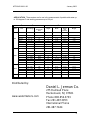
APPLICATION. These meters are for use in the measurement of potable cold water up
to 120 degrees F and working pressures up to 150 psi.
P
ERFORMANCE DATA DIMENSIONS
Model Size Flow Range
Recommended
Continuous
Flow
Length Width Height
(Lid
Closed)
Weight
5/8” x 1/2” 1/8 – 20 15 7 1/2 4 5 1/2 3 1/2
5/8” x 3/4” 1/8 – 20 15 7 1/2 4 5 1/2 3 1/2
3/4” x 3/4”S 1/4 – 30 15 7 1/2 3 7/8 6 3/16 4 3/5
3/4”x3/4” 1/4 – 30 15 9 3 7/8 6 3/16 4 4/5
3/4”x1” 1/4 – 30 15 9 3 7/8 6 3/16 4 4/5
1” 1/2 – 50 25 10 3/4 6 15/16 6 5/8 10 1/5
1 1/2” 1 1/2 – 100 50 12 5/8 or 13 7 1/2 or 8 1/2 8 7/8 21 7/10 or 23 7/10
C700
2” 2 – 160 80 15 1/4 or 17 8 3/4 8 1/8 36 7/10 or 38 7/10
1 1/2” 3 – 200 160 10 7 3/8 7 3/4 19 1/2 or 20
2” 3 – 200 160 10 7 3/8 7 3/4 21 1/2 or 22
3” 4 – 750 600 11 7/8 7 3/8 11 7/8 33 3/8
4” 7 – 1250 1000 14 9 10 3/4 51 1/2
6” 15 – 2500 2000 18 11 13 3/8 90
8” 25 – 3500 2800 20 13 7/16 16 1/16 168
10” 55 – 5500 3200 17 3/4 16 1/8 18 15/16 246
T3000
12” 95 – 7000 4300 19 3/4 19
1/16 20 3/8 278
2” 1/4 – 160 100 17 12 9/16 8 34
3” 1/4 – 650 325 17 13 1/4 9 7/16 55 1/4
4” 1/4 – 1150 575 20 14 1/8 10 7/8 67 1/8
6” 3/4 – 2500 1560 24 17 9/16 8 1/8 145
C3000
8” 1 1/2 – 3000 1875 34 or 34 1/2 20 1/2 16 227 or 285
H3200 3” 5 – 400 300 14 3/8 7 3/8 8 13/16 17 1/4
Distributed by:
www.watermeters.com
Daniel L. Jerman Co.
275 Railroad Place
Hackensack, NJ 07601
Phone 800.654.3733
Fax 201.487.3953
International Phone
201.487.7444
-
 1
1
-
 2
2
-
 3
3
-
 4
4


Amco H3200 Installation And Start-Up Instructions
- Type
- Installation And Start-Up Instructions
Ask a question and I''ll find the answer in the document
Finding information in a document is now easier with AI
Other documents
-
American Flow Control B84B User guide
-
-
-
Fluke 3000 FC generelt vedligeholdelsessystem User guide
-
 ProPlumber PPYH-4 Installation guide
-
-
-
 Liquid Controls M-30 Installation guide
-
 Arrowhead Brass PK6004 Installation guide
-
 EJ USA 22042 Installation guide


