Triton Systems 9700 series Owner's manual

Type
Owner's manual

This manual is also suitable for

Serial Printer Controller
rePlaCement
91xx / mako / 97xx
TDN 07100-00127 Oct 09, 2012
COPYRIGHT NOTICE
© 2012 Triton. All Rights Reserved. TRITON logo is
a registered trademark of Triton Systems of Delaware.
CorPorate HeadquarterS:
21405 B Street
Long Beach, MS 39560
Phone: (228) 575-3100
Fax: (228) 575-3101
2
Printer Controller rePlaCement ProCedures
Document Updates
Oct 09 2012 Original
3
91xx, mako, and 97xx
PurPoSe
This guide covers the steps for replacing your current printer controller with a new model. This procedure
includes a list of all tools and hardware necessary for the replacement as well as the steps involved.
SCoPe
This procedure applies to all service personnel involved in the process of maintaining or converting
Triton ATMs.
aPPliCation
This conversion kit applies to Model 91xx, Mako, and 97xx
units.
required PartS and toolS
Kit P/N 06200-18182
This kit replaces kit P/N 06200-08182 which introduced the printer controller (P/N 01500-00119) with
a newer power connection. It also included the replacement power cable. The original printer controller
(P/N 01500-00109), shown on the left below, had the old type connection.
This kit replaces the original printer controller (P/N 01500-00109) and subsequent printer controller
(P/N 01500-00119) with P/N 01500-10119 (jumpers included) in model 91xx, MAKO, and 97xx units.
It also includes a replacement power cable. A jumper power cable is provided for the 91xx and Mako
units. Route the new power cable in the same manner as the old cable.
In additon to the newer power connection, the newest printer controller has a new cutter
connection. The supplier of printer assemblies has replaced a connector on their printer controller and
cutter due to a connector going end of life. The change is not backwards compatible and parts are not
available to connect older controller boards with new cutters, or new controller boards with old cutters.
The new connector is a JST connector. This kit includes the new cutter and cutter extension cable for
the JST connection
01500-00119 and 01500-10119 power connection
01500-00109 power connection
Previous
New
Previous
01500-00109 and 01500-00119 cutter connector
New
01500-10119 JST cutter connector
4
Printer Controller rePlaCement ProCedures
Item Description Qty
01500-10119 Printer Controller|DIP Switches 60/80mm Printers| 115.2K Baud|Firmware-
28000-00063 v1.18 - JST cutter connector
1
01060-00872 Connector|Jumper|2-Position|Jumper Shunt for .100 inch|2-Pin PCB
Connector|Tin ROHS
1
09120-07063 Cable, printer power, 76” 1
03072-00015 6 Inches TY Wraps ROHS 10
28000-00063 Ver 1.18,|PT230P01, 23, Apr.2007|Firmware for Seiko printer ctrls IF2301,
IF2303
1
09120-07109 Serial printer power adapter cable 1
09800-10103 Printer Cutter, 60mm Thermal Printer ROHS - JST cutter connector 1
09120-10195 Cutter extension cable, JST connector 1
07100-00127 Printer Controller Conguration Guide 1
TOOLS REQUIRED
#2 philips screwdriver / nut driver or open end wrench 11/32”
KIT 06200-18182
Field Replacement Kit, Serial Printer Controller w/Conguration Dip
Switches and Power Cable
5
91xx, mako, and 97xx
5. Refer to the pictures on the next page for illustrative routing of the extension cable on Mako and
91xx units.
remove and rePlaCe ProCedureS
1. Refer to the applicable service manual for your unit, or to the representative steps below, to remove
and replace the printer controller and/or the cutter.
Before proceeding, follow these steps to remove power from the ATM:
Enter Management Functions > System Parameters > Shut Down the Terminal. When prompted,
unlock and open the ATM control panel and turn power OFF (0) on the ATMs power supply.
OR: Unlock and open the ATM control panel. Turn the power switch to the OFF (0) position.
If possible, unplug the ATM power cord at the wall outlet.
7. Refer to the charts on the last page to ensure your controllers DIP switches and jumpers are
congured properly for your unit.
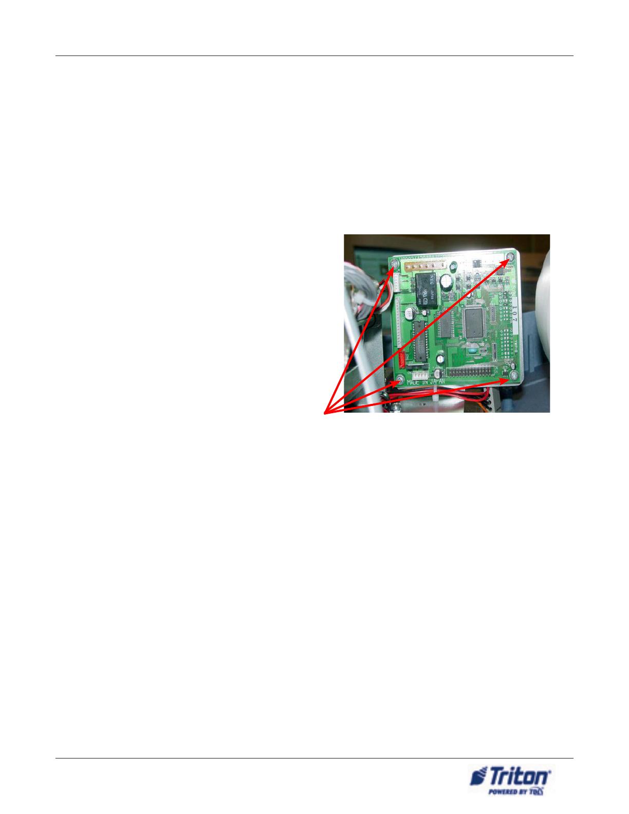
All printer controllers are mounted in much the
same manner. Your printer controller may have a
protective cover. Ensure it is in place before re-
powering the unit. Refer to the example shown
for the basic steps needed to remove the printer
controller. Installation is the reverse of removal.
Retain all hardware. Handle the new controller
with care, it is an Electro-Static sensitive device.
Ensure power is removed from the unit.
Remove the protective cover if applicable.
Disconnect all cables. Make a connection
chart if necessary.
Remove the 4 (four) screws attaching the
controller to its bracket (representative)
Set dip switches and jumpers on new con-
troller.
Installation is the reverse
6. Ensure any other cables removed from the old printer controller are connected properly to the new
printer controller.
2. Remove the old cutter and install the new cutter (09800-10103) with the JST connector.
3. Replace the existing cutter extension cable with the new (09120-10195) and route in the same
manner as the old cable. Ty wrap as necessary to ensure there is no interference with the operation
of the printer, especially the paper roll and feed mechanism.
4. Replace the existing power cable with the new (09120-07063) cable and route in the same manner
as the old cable. Ty wrap as necessary to ensure there is no interference with the printer paper, feed
mechanism, or any other moveable part.
8. Ensure all cables are secure and connected properly before powering on the unit. Load the printer
with paper and test the operation of the unit.
6
Printer Controller rePlaCement ProCedures
Extension cable installed, Mako example:
Extension cable
connector
Original Printer
controller cable
connector
New printer controller
cable connector
Extension cable installed, 91xx example:
Original Printer
controller cable
connector
Extension cable
connectors
Install ty wrap
DIP Switch Conguration - 91xx/97xx/MAKO
DIP Bank 1 DIP Bank 2
#7 switch ON, others OFF #1 switch ON, others OFF
Jumper Configuration Table
Product JP1 JP3 JP4
ALL Shorted Pins 1 - 2 Pins 1 - 2
* All other jumpers are left open.
CONFIGURATION
JP3JP1 JP4JP3JP1 JP4
DIP - 1
ON
1 2 3 4 5 6 7 8 9 10
DIP - 1
ON
1 2 3 4 5 6 7 8 9 10
DIP - 2
ON
1 2 3 4 5 6 7 8
DIP - 2
ON
1 2 3 4 5 6 7 8
  • Page 1 1
  • Page 2 2
  • Page 3 3
  • Page 4 4
  • Page 5 5
  • Page 6 6

Triton Systems 9700 series Owner's manual

Type
Owner's manual
This manual is also suitable for

Ask a question and I''ll find the answer in the document

Finding information in a document is now easier with AI