Desa FA-20BB Owner's manual

Category
Space heaters
Type
Owner's manual

This manual is also suitable for

BLUE FLAME
VENT-FREE NATURAL GAS HEATER
OWNER’S OPERATION AND INSTALLATION MANUAL
Save this manual for future reference.
®
FA-20BB
FAS-20BB
FA-30BB
FAS-30BB
FGH-30NGB
20,000 and 30,000
Btu/Hr Models
WARNING: If the information in this manual is
not followed exactly, a fire or explosion may
result causing property damage, personal
injury, or loss of life.
Do not store or use gasoline or other
flammable vapors and liquids in the vicinity of
this or any other appliance.
WHAT TO DO IF YOU SMELL GAS
Do not try to light any appliance.
Do not touch any electrical switch; do not use
any phone in your building.
Immediately call your gas supplier from a
neighbor’s phone. Follow the gas supplier’s
instructions.
If you cannot reach your gas supplier, call the
fire department.
Installation and service must be performed by
a qualified installer, service agency, or the
gas supplier.
This appliance may be installed in an aftermarket* manufactured (mobile) home, where not prohib-
ited by state or local codes.
* Aftermarket: Completion of sale, not for purpose of resale, from the manufacturer
WARNING: This is an unvented
gas-fired heater. It uses air (oxy-
gen) from the room in which it
is installed. Provisions for ad-
equate combustion and venti-
lation air must be provided.
Refer to
Air For Combustion
and Ventilation
section on page
4 of this manual.
WARNING: Improper instal-
lation, adjustment, alteration,
service, or maintenance can
cause injury or property dam-
age. Refer to this manual for
correct installation and op-
erational procedures. For as-
sistance or additional infor-
mation consult a qualified in-
staller, service agency, or the
gas supplier.
2
105568
BLUE FLAME NATURAL GAS HEATER
Carbon Monoxide Poisoning: Early
signs of carbon monoxide poisoning re-
semble the flu, with headaches, dizziness,
or nausea. If you have these signs, the heater
may not be working properly. Get fresh air
at once! Have heater serviced. Some people
are more affected by carbon monoxide than
others. These include pregnant women, per-
sons with heart or lung disease or anemia,
those under the influence of alcohol, and
those at high altitudes.
Natural Gas: Natural gas is odorless. An
odor-making agent is added to natural gas.
The odor helps you detect a natural gas leak.
However, the odor added to natural gas can
fade. Natural gas may be present even though
no odor exists.
Make certain you read and understand all
Warnings. Keep this manual for reference.
It is your guide to safe and proper operation
of this heater.
SAFETY
INFORMATION
1. This appliance is only for use with the
type of gas indicated on the rating plate.
This appliance is not convertible for use
with other gases.
2. If you smell gas
shut off gas supply
do not try to light any appliance
do not touch any electrical switch; do
not use any phone in your building
immediately call your gas supplier
from a neighbor’s phone. Follow the
gas supplier’s instructions
if you cannot reach your gas supplier,
call the fire department
3. This heater shall not be installed in a
bedroom or bathroom.
4. Never install the heater
in a recreational vehicle
where curtains, furniture, clothing, or
other flammable objects are less than
36 inches from the front, top, or sides
of the heater
as a fireplace insert
in high traffic areas
in windy or drafty areas
5. This heater needs fresh, outside air ven-
tilation to run properly. This heater has
an oxygen depletion sensor (ODS) pi-
lot light safety system. The ODS shuts
down the heater if not enough fresh air
is available. See Air for Combustion
and Ventilation, pages 4 through 6.
6. Keep all air openings in front and bot-
tom of heater clear and free of debris.
This will insure enough air for proper
combustion.
7. If heater shuts off, do not relight until
you provide fresh, outside air. If heater
keeps shutting off, have it serviced.
WARNING ICON G 001
WARNINGS
IMPORTANT: Read this Owner’s
Manual carefully and completely
before trying to assemble, oper-
ate, or service this heater. Im-
proper use of this heater can
cause serious injury or death from
burns, fire, explosion, electrical
shock, and carbon monoxide
poisoning.
DANGER: Carbon monoxide
poisoning may lead to death!
WARNING: Any change to
this heater or its controls can be
dangerous.
8. Do not run heater
where flammable liquids or vapors
are used or stored
under dusty conditions
9. Before using furniture polish, wax, car-
pet cleaner, or similar products, turn
heater off. If heated, the vapors from
these products may create a white pow-
der residue within burner box or on
adjacent walls or furniture.
10. Never place any objects on the heater.
11. Surface of heater becomes very hot
when running heater. Keep children and
adults away from hot surface to avoid
burns or clothing ignition. Heater will
remain hot for a time after shutdown.
Allow surface to cool before touching.
12. Carefully supervise young children
when they are in same room with
heater.
13. Make sure grill guard is in place be-
fore running heater.
14. Do not use heater if any part has been
under water. Immediately call a quali-
fied service technician to inspect the
room heater and to replace any part of
the control system and any gas control
which has been under water.
15. Turn off and unplug heater and let cool
before servicing. Only a qualified ser-
vice person should service and repair
heater.
16. Operating heater above elevations of
4,500 feet could cause pilot outage.
3
105568
OWNER’S MANUAL
PRODUCT
IDENTIFICATION
LOCAL CODES
Install and use heater with care. Follow all
local codes. In the absence of local codes, use
the latest edition of National Fuel Gas Code
ANS Z223.1, also known as NFPA 54*.
*Available from:
American National Standards Institute, Inc.
1430 Broadway
New York, NY 10018
National Fire Protection Association, Inc.
Batterymarch Park
Quincy, MA 02269
UNPACKING
1. Remove heater from carton.
2. Remove all protective packaging ap-
plied to heater for shipment.
3. Check heater for any shipping damage.
If heater is damaged, promptly inform
dealer where you bought heater.
Figure 1 - Vent-Free Natural Gas Heater (Models FAS-20BB Shown)
Ignitor Button
Control Knob
Heater
Cabinet
Front
Panel
PRODUCT
FEATURES
SAFETY DEVICE
This heater has a pilot with an Oxygen
Depletion Sensor Shutoff System (ODS).
The ODS/pilot is a required feature for vent-
free room heaters. The ODS/pilot shuts off
the heater if there is not enough fresh air.
PIEZO IGNITION SYSTEM
This heater has a piezo ignitor. This system
requires no matches, batteries, or other
sources to light heater.
THERMOSTATIC HEAT
CONTROL ON THERMOSTAT
MODELS FAS-20BB AND
FAS30-BB
These heaters have a control valve with a
thermostat sensing bulb. This results in the
greatest heater comfort and may result in
lower gas bills.
Glass
Panel
Grill
Guard
4
105568
BLUE FLAME NATURAL GAS HEATER
AIR FOR
COMBUSTION AND
VENTILATION
Today’s homes are built more energy effi-
cient than ever. New materials, increased
insulation, and new construction methods
help reduce heat loss in homes. Home owners
weather strip and caulk around windows and
doors to keep the cold air out and the warm air
in. During heating months, home owners
want their homes as airtight as possible.
While it is good to make your home energy
efficient, your home needs to breathe. Fresh
air must enter your home. All fuel-burning
appliances need fresh air for proper com-
bustion and ventilation.
Exhaust fans, fireplaces, clothes dryers, and
fuel burning appliances draw air from the
house to operate. You must provide ad-
equate fresh air for these appliances. This
will insure proper venting of vented fuel-
burning appliances.
WARNING: This heater shall
not be installed in a confined
space or unusually tight con-
struction unless provisions are
provided for adequate combus-
tion and ventilation air. Read the
following instructions to insure
proper fresh air for this and other
fuel-burning appliances in your
home.
PROVIDING ADEQUATE
VENTILATION
The following are excerpts from National
Fuel Gas Code. NFPA 54/ANS Z223.1, Sec-
tion 5.3, Air for Combustion and Ventilation.
All spaces in homes fall into one of the three
following ventilation classifications:
1. Unusually Tight Construction
2. Unconfined Space
3. Confined Space
The information on pages 4 through 6 will
help you classify your space and provide
adequate ventilation.
Unusually Tight Construction
The air that leaks around doors and win-
dows may provide enough fresh air for
combustion and ventilation. However, in
buildings of unusually tight construction,
you must provide additional fresh air.
Unusually tight construction is de-
fined as construction where:
a. walls and ceilings exposed to the
outside atmosphere have a con-
tinuous water vapor retarder with
a rating of (one perm 6x10
-11
kg
per pa-sec-m
2
) or less with open-
ings gasketed or sealed
and
b. weather stripping has been
added on openable windows and
doors
and
c. caulking or sealants are applied
to areas such as joints around
window and door frames, be-
tween sole plates and floors, be-
tween wall-ceiling joints, be-
tween wall panels, at penetra-
tions for plumbing, electrical, and
gas lines, and at other openings.
If your home meets all of the three
criteria above, you must provide ad-
ditional fresh air. See
Ventilation Air
From Outdoors
, page 6.
If your home does not meet all of the
three criteria above, proceed to
De-
termining Fresh-Air Flow For Heater
Location
, page 5.
Confined and Unconfined Space
The National Fuel Gas Code (ANS Z223.1,
1992 Section 5.3) defines a confined space
as a space whose volume is less than 50
cubic feet per 1,000 Btu per hour (4.8 m
3
per
kw) of the aggregate input rating of all
appliances installed in that space and an
unconfining space as a space whose volume
is not less than 50 cubic feet per 1,000 Btu
per hour (4.8 m
3
per kw) of the aggregate
input rating of all appliances installed in that
space. Rooms communicating directly with
the space in which the appliances are in-
stalled*, through openings not furnished
with doors, are considered a part of the
unconfined space.
This heater shall not be installed in a con-
fined space or unusually tight construction
unless provisions are provided for adequate
combustion and ventilation air.
* Adjoining rooms are communicating only
if there are doorless passageways or ventila-
tion grills between them.
5
105568
OWNER’S MANUAL
AIR FOR
COMBUSTION AND
VENTILATION
Continued
DETERMINING FRESH-AIR FLOW FOR HEATER LOCATION
Determining if You Have a Confined or Unconfined Space
Use this worksheet to determine if you have a confined or unconfined space.
Space: Includes the room in which you will install heater plus any adjoining rooms with doorless passageways or ventilation grills between
the rooms.
1. Determine the volume of the space (length x width x height).
Length x Width x Height = _________________cu. ft. (volume of space)
Example:
Space size 20 ft. (length) x 16 ft. (width) x 8 ft. (ceiling height) = 2560 cu. ft. (volume of space)
If additional ventilation to adjoining room is supplied with grills or openings, add the volume of these rooms to the total volume of
the space.
2. Divide the space volume by 50 cubic feet to determine the maximum Btu/Hr the space can support.
_________________ (volume of space) ÷ 50 cu. ft. = (Maximum Btu/Hr the space can support)
Example:
2560 cu. ft. (volume of space) ÷ 50 cu. ft. = 51.2 or 51,200 (maximum Btu/Hr the space can support)
3. Add the Btu/Hr of all fuel burning appliances in the space.
Vent-free heater ___________________Btu/Hr
Gas water heater* ___________________Btu/Hr
Gas furnace ___________________Btu/Hr
Vented gas heater ___________________Btu/Hr
Gas fireplace logs ___________________Btu/Hr
Other gas appliances* + ___________________Btu/Hr
Total = ___________________Btu/Hr
* Do not include direct-vent gas appliances. Direct-vent draws combustion air from the outdoors and vents to the outdoors.
4. Compare the maximum Btu/Hr the space can support with the actual amount of Btu/Hr used.
_________________ Btu/Hr (maximum the space can support)
_________________ Btu/Hr (actual amount of Btu/Hr used)
Example:
51,200 Btu/Hr (maximum the space can support)
60,000 Btu/Hr (actual amount of Btu/Hr used)
The space in the above example is a confined space because the actual Btu/Hr used is more than the maximum Btu/Hr the space can support.
You must provide additional fresh air. Your options are as follows:
A. Rework worksheet, adding the space of an adjoining room. If the extra space provides an unconfined space, remove door to adjoin-
ing room or add ventilation grills between rooms. See Ventilation Air From Inside Building, page 6.
B. Vent room directly to the outdoors. See Ventilation Air From Outdoors, page 6.
C. Install a lower Btu/Hr heater, if lower Btu/Hr size makes room unconfined.
If the actual Btu/Hr used is less than the maximum Btu/Hr the space can support, the space is an unconfined space. You will need no
additional fresh air ventilation.
Continued
Example:
Gas water heater
40,000
Btu/Hr
Vent-free heater +
20,000
Btu/Hr
Total =
60,000
Btu/Hr
WARNING: If the area in which the heater may be operated is smaller than that defined as an unconfined space,
or if building is of unusually tight construction, provide adequate combustion and ventilation air by one of the
methods described in the
National Fuel Gas Code, ANS Z223.1, 1992, Section 5.3
or applicable local codes.
6
105568
BLUE FLAME NATURAL GAS HEATER
Figure 3 - Ventilation Air from Outdoors
Outlet
Air
Ventilated
Attic
Outlet
Air
Inlet
Air
Inlet Air
Ventilated
Crawl Space
To
Crawl
Space
To Attic
Ventilation Air From Outdoors
Provide extra fresh air by using ventilation
grills or ducts. You must provide two per-
manent openings: one within 12" of the
ceiling and one within 12" of the floor.
Connect these items directly to the outdoors
or spaces open to the outdoors. These spaces
include attics and crawl spaces. Follow the
National Fuel Gas Code NFPA 54/ANS
Z223.1, Section 5.3, Air for Combustion and
Ventilation for required size of ventilation
grills or ducts.
IMPORTANT:
Do not provide openings
for inlet or outlet air into attic if attic has a
thermostat-controlled power vent. Heated
air entering the attic will activate the power
vent.
AIR FOR
COMBUSTION AND
VENTILATION
Continued
Or
Remove
Door into
Adjoining
Room,
Option 3
Ventilation Grills
Into Adjoining Room,
Option 2
12"
12"
Ventilation
Grills
into Adjoining
Room,
Option 1
VENTILATION AIR
Ventilation Air From Inside
Building
This fresh air would come from an adjoining
unconfined space. When ventilating to an
adjoining unconfined space, you must pro-
vide two permanent openings: one within
12" of the ceiling and one within 12" of the
floor on the wall connecting the two spaces
(see options 1 and 2, Figure 2). You can also
remove door into adjoining room (see op-
tion 3, Figure 2). Follow the National Fuel
Gas Code NFPA 54/ANS Z223.1, Section
5.3, Air for Combustion and Ventilation for
required size of ventilation grills or ducts.
Figure 2 - Ventilation Air from Inside Building
WARNING: Rework work-
sheet, adding the space of the
adjoining unconfined space. The
combined spaces must have
enough fresh air to supply all
appliances in both spaces.
7
105568
OWNER’S MANUAL
36"
2"
FLOOR
CEILING
Minimum
Minimum to Top
of Carpeting, Tile,
or Other Combustible
Material
6"
Minimum
From
Sides of
Heater
Left
Side
Right
Side
INSTALLATION
Continued
CHECK GAS TYPE
Use only natural gas. If your gas supply is
not natural, do not install heater. Call dealer
where you bought heater for proper type
heater.
INSTALLATION ITEMS
Before installing heater, make sure you have
the items listed below:
piping (check local codes)
sealant (resistant to propane/LP gas)
manual shutoff valve *
ground joint union
test gauge connection *
sediment trap
tee joint
pipe wrench
* An A.G.A. design-certified manual shutoff
valve with 1/8" NPT tap is an acceptable
alternative to test gauge connection. Pur-
chase the optional A.G.A. design-certified
manual shutoff valve from your dealer. See
Accessories, page 19.
NOTICE: A qualified service per-
son must install heater. Follow
all local codes.
WARNING: Maintain the mini-
mum clearances shown in Figure
4. If you can, provide greater clear-
ances from floor, ceiling, and join-
ing wall.
CAUTION: If you install the
heater in a home garage
heater pilot and burner must be
at least 18 inches above floor
locate heater where moving ve-
hicle will not hit it
IMPORTANT:
Vent-free heaters add mois-
ture to the air. Although this is beneficial,
installing heater in rooms without enough
ventilation air may cause mildew to form
from too much moisture. See Air for Com-
bustion and Ventilation, pages 4 through 6.
CAUTION: This heater cre-
ates warm air currents. These
currents move heat to wall sur-
faces next to heater. Installing
heater next to vinyl or cloth wall
coverings or operating heater
where impurities (such as to-
bacco smoke, aromatic candles,
cleaning fluids, oil or kerosene
lamps, etc.) in the air exist, may
discolor walls.
WARNING: Never install the
heater
in a bedroom or bathroom
in a recreational vehicle
where curtains, furniture,
clothing, or other flammable
objects are less than 36 inches
from the front, top, or sides of
the heater
as a fireplace insert
in high traffic areas
in windy or drafty areas
You can locate heater on floor, away from a
wall. An optional floor mounting stand is
needed. Purchase the floor mounting stand
from your dealer. See Accessories, page 19.
NOTICE: This heater is intended
for use as supplemental heat. Use
this heater along with your pri-
mary heating system. Do not in-
stall this heater as your primary
heat source. If you have a central
heating system, you may run
system’s circulating blower while
using heater. This will help circu-
late the heat throughout the
house. In the event of a power
outage, you can use this heater
as your primary heat source.
LOCATING HEATER
This heater is designed to be mounted on a wall.
Figure 4 - Mounting Clearances As Viewed
From Front of Heater
For convenience and efficiency, install heater
where there is easy access for operation,
inspection, and service
in coldest part of room
An optional fan kit is available from your
dealer. See Accessories, page 19. If plan-
ning to use fan, locate heater near an electri-
cal outlet.
INSTALLING HEATER TO
WALL
Mounting Bracket
The mounting bracket is located on back
panel of heater. It has been taped there for
shipping. Remove mounting bracket from
back panel.
Mounting
Bracket
Figure 5 - Mounting Bracket
8
105568
BLUE FLAME NATURAL GAS HEATER
Attaching Mounting Bracket To
Wall
Note:
Wall anchors, mounting screws, and
spacers are in hardware package. The hard-
ware package is provided with heater.
Models FA-30BB, FAS-30BB, and
FGH-30NGB
Models FA-20BB and FAS-20BB
Figure 7 - Mounting Bracket Clearances
Figure 8 - Folding Anchor
WARNING: Maintain minimum
clearances shown in Figure 7. If
you can, provide greater clear-
ances from floor and joining wall.
Figure 6 - Removing Front Panel Of Heater
Methods For Attaching
Mounting Bracket To Wall
Only use last hole on each end of mounting
bracket to attach bracket to wall. These two
holes are 16 inches apart from their centers.
Attach mounting bracket to wall in one of
two ways:
1. Attaching to wall stud
2. Attaching to wall anchor
Attaching To Wall Stud
This method provides the strongest hold.
Insert mounting screws through mounting
bracket and into wall studs.
Attaching To Wall Anchor
This method allows you to attach mounting
bracket to hollow walls (wall areas between
studs) or to solid walls (concrete or masonry).
Decide which method better suits your needs.
Either method will provide a secure hold for
the mounting bracket.
Removing Front Panel Of Heater
1. Remove two screws near bottom cor-
ners of front panel.
2. Lift straight up on grill guard until it stops.
Grill guard will slide up about 1/4".
3. Pull bottom of front panel forward, then
down.
4. Remove cardboard packing from grill
and glass.
INSTALLATION
Continued
Marking Screw Locations
1. Tape mounting bracket to wall where
heater will be located. Make sure
mounting bracket is level.
2. Mark screw locations on wall (see Fig-
ure 7).
Note: Only mark last hole on each end
of mounting bracket. Insert mounting
screws through these holes only.
3. Remove tape and mounting bracket
from wall.
Attaching To Wall Stud Method
For attaching mounting bracket to wall studs
1. Drill holes at marked locations using
9/64" drill bit.
2. Place mounting bracket onto wall. Line
up last hole on each end of bracket with
holes drilled in wall.
3. Insert mounting screws through bracket
and into wall studs.
4. Tighten screws until mounting bracket
is firmly fastened to wall studs.
Attaching To Wall Anchor Method
For attaching mounting bracket to hollow
walls (wall areas between studs) or solid
walls (concrete or masonry)
1. Drill holes at marked locations using
5/16" drill bit. For solid walls (concrete
or masonry), drill at least 1" deep.
2. Fold wall anchor as shown in Figure 8.
3. Insert wall anchor (wings first) into
hole. Tap anchor flush to wall.
4. For thin walls (1/2" or less), insert red
key into wall anchor. Push red key to
“pop” open anchor wings.
IMPORTANT:
Do not hammer key!
For thick walls (over 1/2" thick) or solid
walls, do not pop open wings.
5. Place mounting bracket onto wall. Line
up last hole on each end of bracket with
wall anchors.
6. Insert mounting screws through bracket
and into wall anchors.
7. Tighten screws until mounting bracket
is firmly fastened to wall.
Figure 9 - Popping Open Anchor Wings
For Thin Walls
17
1
/
2
"
Min.
10
1
/
4
"
Min.
17
3
/
8
"
Adjoining Wall
Only Insert Mounting
Screws Through Last
Hole On Each End
Floor
17
3
/
8
"
17
1
/
2
"
Min.
6
1
/
2
"
Min.
Adjoining Wall
Only Insert Mounting
Screws Through Last
Hole On Each End
Floor
9
105568
OWNER’S MANUAL
Tee Joint
Pipe Nipple
Cap
INSTALLATION
Continued
Figure 11 - Installing Bottom Mounting
Screws
Figure 10 - Mounting Heater Onto Mount-
ing Bracket
Horizontal Slots
Mounting Bracket
(attached to wall)
Stand-Out Tab
Placing Heater On Mounting
Bracket
1. Locate two horizontal slots on back
panel of heater.
2. Place heater onto mounting bracket.
Slide horizontal slots onto stand-out tabs
on mounting bracket (see Figure 10).
Installing Bottom Mounting
Screws
1. Locate two bottom mounting holes.
These holes are near bottom on back
panel of heater (see Figure 11).
2. Mark screw locations on wall.
3. Remove heater from mounting bracket.
4. If installing bottom mounting screws
into hollow or solid wall, install wall
anchors. Follow steps 1 through 4 un-
der Attaching To Wall Anchor Method,
page 8.
If installing bottom mounting screw
into wall stud, drill holes at marked lo-
cations using 9/64" drill bit.
5. Replace heater onto mounting bracket.
6. Place spacers between bottom mount-
ing holes and wall anchor or drilled hole.
Continued
CONNECTING TO GAS
SUPPLY
NOTICE: A qualified service per-
son must connect heater to gas
supply. Follow all local codes.
WARNING: Never connect
heater to private (non-utility) gas
well. This gas is commonly known
as wellhead gas.
Typical Inlet Pipe Diameters
FA-20BB, 3/8" or greater
FAS-20BB
FA-30BB, 1/2" or greater
FAS-30BB,
FGH-30NG
Installation must include a manual shutoff
valve, union, and plugged 1/8" NPT tap.
Locate NPT tap within reach for test gauge
hook up. NPT tap must be upstream from
heater (see Figure 12).
Apply pipe joint sealant lightly to male
threads. This will prevent excess sealant
from going into pipe. Excess sealant in pipe
could result in clogged heater valves.
Install sediment trap in supply line as shown
in Figure 12. Locate sediment trap where it
is within reach for cleaning. Locate sedi-
ment trap where trapped matter is not likely
to freeze. A sediment trap traps moisture
and contaminants. This keeps them from
going into heater controls. If sediment trap
is not installed or is installed wrong, heater
may not run properly.
Hold pressure regulator with wrench when
connecting it to gas piping and/or fittings.
CAUTION: Use only new,
black iron or steel pipe. Inter-
nally-tinned copper tubing may
be used in certain areas. Check
your local codes. Use pipe of large
enough diameter to allow proper
gas volume to heater. If pipe is
too small, undue loss of pres-
sure will occur.
CAUTION: Use pipe joint seal-
ant that is resistant to natural gas.
IMPORTANT:
Check gas line pressure be-
fore connecting heater to gas line. Gas line
pressure must be no greater than 14 inches
of water. If gas line pressure is higher,
heater regulator damage could occur.
Figure 12 - Gas Connection
* An A.G.A. design-certified manual shutoff valve with 1/8" NPT tap is an acceptable
alternative to test gauge connection. Purchase the optional A.G.A. design-certified manual
shutoff valve from your dealer. See Accessories, page 19.
7. Hold spacer in place with one hand.
With other hand, insert mounting screw
through bottom mounting hole and
spacer. Place tip of screw in opening
of wall anchor or drilled hole.
8. Tighten both screws until heater is firmly
secured to wall. Do not over tighten.
Note:
Do not replace front panel at this
time. Replace front panel after making
gas connections and checking for leaks.
(see page 10).
Pressure
Regulator
Test
Gauge
Connection *
3/8" NPT
Pipe Nipple
Sediment
Trap
3" Minimum
Typical Inlet
Pipe from
Gas Meter
(4" W.C. to
10.5" W.C.
Pressure)
Heater
Cabinet
Ground
Joint Union
Tee Joint
Reducer Bushing
to 1/8" NPT
1/8" NPT Plug Tap
Manual Shutoff
Valve *
10
105568
BLUE FLAME NATURAL GAS HEATER
O
N
POSI
T
O
PO
S
Figure 13 - Manual Shutoff Valve
Figure 14 - Checking Gas Joints
Manual
Shutoff
Valve
Closed
WARNING: Test all gas pip-
ing and connections for leaks
after installation or servicing.
Correct all leaks at once.
WARNING: Never use an open
flame to check for a leak. Apply a
mixture of liquid soap and water
to all joints. Bubbles forming show
a leak. Correct all leaks at once.
Pressure Testing Gas Supply
Piping System
Test Pressures In Excess Of 1/2 PSIG
(3.5 K Pa)
1. Disconnect heater and its individual
manual shutoff valve from gas supply
piping system. Pressures in excess of
1/2 psig will damage heater regulator.
2. Cap off open end of gas pipe where
manual shutoff valve was connected.
3. Pressurize supply piping system by ei-
ther using compressed air or opening
main gas valve located on or near gas
meter.
4. Check all joints of gas supply piping
system. Apply mixture of liquid soap
and water to gas joints. Bubbles form-
ing show a leak.
5. Correct all leaks at once.
CHECKING GAS
CONNECTIONS
INSTALLATION
Continued
Test Pressures Equal To or Less Than
1/2 PSIG (3.5 K Pa)
1. Close manual shutoff valve (see Fig-
ure 13).
2. Pressurize supply piping system by ei-
ther using compressed air or opening
main gas valve located on or near gas
meter.
3. Check all joints from gas meter to
manual shutoff valve (see Figure 14).
Apply mixture of liquid soap and wa-
ter to gas joints. Bubbles forming show
a leak.
4. Correct all leaks at once.
Open
Pressure Testing Heater Gas
Connections
1. Open manual shutoff valve (see Fig-
ure 13).
2. Open main gas valve located on or near
gas meter.
3. Make sure control knob of heater is in
the OFF position.
4. Check all joints from manual shutoff
valve to thermostat gas valve (see Fig-
ure 14). Apply mixture of liquid soap
and water to gas joints. Bubbles form-
ing show a leak.
5. Correct all leaks at once.
6. Light heater (see Operating Heater,
pages 11 and 12 for thermostat models
or pages 12 and 13 for non-thermostat
models). Check all other internal joints
for leaks.
7. Turn off heater (see To Turn Off Gas
to Appliance, page 12 for thermostat
models or page 13 for non-thermostat
models).
8. Replace front panel.
Manual
Shutoff Valve
Gas Meter
Gas Valve
11
105568
OWNER’S MANUAL
PILOT
LO
OFF
HI
CAUTION: Do not try to adjust
heating levels by using the
manual shutoff valve.
Figure 16 - Pilot
LIGHTING
INSTRUCTIONS
1. STOP! Read the safety information
above.
2. Make sure manual shutoff valve is
fully open.
3. Turn control knob clockwise
Clockwise
to the OFF position.
4. Wait five (5) minutes to clear out any
gas. Then smell for gas, including near
the floor. If you smell gas, STOP! Fol-
low “B” in the safety information in
column 1. If you don’t smell gas, go
to the next step.
5. Turn control knob counterclockwise
C-clockwise
to the PILOT position.
Press in control knob for five (5) sec-
onds (see Figure 15).
Note:
You may be running this
heater for the first time after hook-
ing up to gas supply. If so, the con-
trol knob may need to be pressed in
for 30 seconds. This will allow air to
bleed from the gas system.
If control knob does not pop up
when released, contact a qualified
service person or gas supplier for
repairs.
6. With control knob pressed in, push
down and release ignitor button. This
will light pilot. The pilot is attached
to the front of burner. The pilot can
be seen through the glass panel. If
needed, keep pressing ignitor button
until pilot lights.
Figure 15 - Control Knob In The OFF
Position
Ignitor Button
Control Knob
Note:
If pilot does not stay lit, refer
to Troubleshooting, pages 15 through
17. Also contact a qualified service
person or gas supplier for repairs.
Until repairs are made, light pilot with
match. To light pilot with match, see
Manual Lighting Procedure, page 12.
7. Keep control knob pressed in for 30
seconds after lighting pilot. After 30
seconds, release control knob.
If control knob does not pop up when
released, contact a qualified service
person or gas supplier for repairs.
Note:
If pilot goes out, repeat steps
3 through 7. Wait one (1) minute be-
fore lighting pilot again.
8. Turn control knob counterclockwise
C-clockwise
to desired heating level. The
main burner should light. Set control
knob to any heat level between HI
and LO.
Thermocouple
Ignitor Electrode
Pilot Burner
OPERATING
HEATER
THERMOSTAT MODELS
FAS-20BB AND FAS-30BB
A. This appliance has a pilot which must
be lighted by hand. When lighting the
pilot, follow these instructions exactly.
B. BEFORE LIGHTING smell all
around the appliance area for gas. Be
sure to smell next to the floor because
some gas is heavier than air and will
settle on the floor.
WHAT TO DO IF YOU SMELL
GAS
Do not try to light any appliance.
Do not touch any electric switch; do
not use any phone in your building.
Immediately call your gas supplier
from a neighbor’s phone. Follow
the gas supplier’s instructions.
If you cannot reach your gas sup-
plier, call the fire department.
C. Use only your hand to push in or turn
the gas control knob. Never use tools.
If the knob will not push in or turn
by hand, don’t try to repair it, call a
qualified service technician or gas
supplier. Force or attempted repair
may result in a fire or explosion.
D. Do not use this appliance if any part
has been under water. Immediately
call a qualified service technician to
inspect the appliance and to replace
any part of the control system and
any gas control which has been un-
der water.
WARNING: If you do not fol-
low these instructions exactly, a
fire or explosion may result caus-
ing property damage, personal
injury or loss of life.
FOR YOUR SAFETY
READ BEFORE
LIGHTING
12
105568
BLUE FLAME NATURAL GAS HEATER
LIGHTING
INSTRUCTIONS
NON-THERMOSTAT MODELS
FA-20BB, FA-30BB AND
FGH-30NGB
A. This appliance has a pilot which must
be lighted by hand. When lighting the
pilot, follow these instructions exactly.
B. BEFORE LIGHTING smell all
around the appliance area for gas. Be
sure to smell next to the floor because
some gas is heavier than air and will
settle on the floor.
WHAT TO DO IF YOU SMELL
GAS
Do not try to light any appliance.
Do not touch any electric switch; do
not use any phone in your building.
Immediately call your gas supplier
from a neighbor’s phone. Follow
the gas supplier’s instructions.
If you cannot reach your gas sup-
plier, call the fire department.
WARNING: If you do not fol-
low these instructions exactly, a
fire or explosion may result caus-
ing property damage, personal
injury or loss of life.
FOR YOUR SAFETY
READ BEFORE
LIGHTING
1. STOP! Read the safety information
above.
2. Make sure manual shutoff valve is
fully open.
3. Turn control knob clockwise
to the OFF position (see Figure 17,
page 13).
4. Wait five (5) minutes to clear out any
gas. Then smell for gas including
near the floor. If you smell gas,
STOP! Follow “B” in the safety in-
formation at left. If you don’t smell
gas, go to the next step.
5. Turn control knob counterclockwise
to the PILOT/IGN position.
Press in control knob for five (5) sec-
onds (see Figure 17, page 13).
Note:
You may be running this
heater for the first time after hook-
ing up to gas supply. If so, the con-
trol knob may need to be pressed in
for 30 seconds. This will allow air to
bleed from the gas system.
If control knob does not pop up
when released, contact a qualified
service person or gas supplier for
repairs.
6. Release control knob pressure and
turn clockwise to OFF.
TO TURN OFF GAS
TO APPLIANCE
1. Remove front panel (see Figure 6,
page 8).
2. Follow steps 1 through 5 under Light-
ing Instructions, page 11.
3. With control knob pressed in, strike
match. Hold match to pilot until pi-
lot lights.
4. Keep control knob pressed in for 30
seconds after lighting pilot. After 30
seconds, release control knob.
5. Replace front panel.
Shutting Off Heater
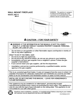
1. Turn control knob clockwise
Clockwise
to the OFF position.
2. Turn off all electric power to the ap-
pliance if service is to be performed.
Shutting Off Burner Only
(pilot stays lit)
Turn control knob clockwise
Clockwise
to
the PILOT position.
THERMOSTAT
CONTROL
OPERATION
The thermostatic control used on these
models differs from standard thermo-
stats. Standard thermostats simply turn
on and off the burner. The thermostat
used on this heater senses the room tem-
perature. The thermostat adjusts the
amount of gas flow to the burner. This
increases or decreases the burner flame
height. At times the room may exceed the
set temperature. If so, the burner will
shut off. The burner will cycle back on
when room temperature drops below the
set temperature. The control knob can be
set to any heat level between HI and LO.
Selecting the HI setting will cause the
burner to remain fully on without modu-
lating down in most cases.
Note:
The thermostat sensing bulb mea-
sures the temperature of air near the
heater cabinet. This may not always agree
with room temperature (depending on
housing construction, installation loca-
tion, room size, open air temperatures,
etc.). Frequent use of your heater will let
you determine your own comfort levels.
MANUAL LIGHTING
PROCEDURE
OPERATING
HEATER
Continued
C. Use only your hand to push in or turn
the gas control knob. Never use tools.
If the knob will not push in or turn
by hand, don’t try to repair it, call a
qualified service technician or gas
supplier. Force or attempted repair
may result in a fire or explosion.
D. Do not use this appliance if any part
has been under water. Immediately
call a qualified service technician to
inspect the appliance and to replace
any part of the control system and
any gas control which has been un-
der water.
13
105568
OWNER’S MANUAL
OPERATING
HEATER
Continued
CAUTION: Do not try to ad-
just heating levels by using the
manual shutoff valve.
TO TURN OFF GAS
TO APPLIANCE
Shutting Off Heater
1. Slightly press in control knob and
turn clockwise to the
PILOT/IGN position.
2. Fully press in control knob and turn
clockwise to the OFF posi-
tion.
3. Turn off all electric power to the ap-
pliance if service is to be performed.
Shutting Off Burner Only (pilot
stays lit)
Slightly press in control knob and turn
clockwise to the PILOT position.
1. Remove front panel (see Figure 6,
page 8).
2. Follow steps 1 through 5 under Light-
ing Instructions, page 12.
3. With control knob pressed in, strike
match. Hold match to pilot until pi-
lot lights.
4. Keep control knob pressed in for 30
seconds after lighting pilot. After 30
seconds, release control knob.
5. Replace front panel.
MANUAL LIGHTING
PROCEDURE
Figure 17 - Control Knob In The OFF
Position
Figure 18 - Pilot
7. Press in control knob and turn back
to PILOT/IGN. This should cause
the piezo ignitor to spark and light
the pilot gas. If needed, repeat steps
5 through 7 until pilot lights.
Note:
If pilot does not stay lit, refer
to Troubleshooting, pages 15
through 17. Also contact a qualified
service person or gas supplier for
repairs. Until repairs are made, light
pilot with match. To light pilot with
match, see Manual Lighting Proce-
dure.
8. Keep control knob pressed in for 30
seconds after lighting pilot. After 30
seconds, release control knob.
Note:
If pilot goes out, repeat steps
3 through 7.
9. To light burner, slightly press in con-
trol knob and turn counterclockwise
. Release downward pres-
sure on control knob while turning.
Set control knob to desired heating
position.
Note:
Both HIGH, MED, and LOW
are locked positions. You must press
in control knob before turning it
from these positions.
Thermocouple
Ignitor Electrode
Pilot Burner
14
105568
BLUE FLAME NATURAL GAS HEATER
Figure 20 - Incorrect Pilot Flame Pattern
Thermocouple
Pilot Burner
INSPECTING
BURNER
Check pilot flame pattern and burner flame
pattern often.
PILOT FLAME PATTERN
Figure 19 shows a correct pilot flame pat-
tern. Figure 20 shows an incorrect pilot
flame pattern. The incorrect pilot flame is
not touching the thermocouple. This will
cause the thermocouple to cool. When the
thermocouple cools, the heater will shut
down.
If pilot flame pattern is incorrect, as shown
in Figure 20
turn heater off (see To Turn Off Gas to Ap-
pliance, page 12 for thermostat models or
page 13 for non-thermostat models)
see Troubleshooting, pages 15 through 17
Figure 19 - Correct Pilot Flame Pattern
Thermocouple
Pilot Burner
BURNER FLAME PATTERN
Figure 21 shows a correct burner flame
pattern. Figure 22 shows an incorrect burner
flame pattern. The incorrect burner flame
pattern shows yellow tipping of the flame. It
also shows the flame higher than 1/2 the
glass panel height.
If burner flame pattern is incorrect, as shown
in Figure 22
turn heater off (see To Turn Off Gas To Ap-
pliance, page 12 for thermostat models or
page 13 for non-thermostat models)
see Troubleshooting, pages 15 through 17
CORRECT FLAME PATTERN
AT HIGH POSITION
1/2
G
Figure 21 - Correct Burner Flame Pattern
Yellow Tipping
1/2
G
INCORRECT FLAME PATTERN
AT HIGH POSITION
Figure 22 - Incorrect Burner Flame Pattern
NOTICE: Do not mistake orange
flames with yellow tipping. Dirt
or other fine particles enter the
heater and burn causing brief
patches of orange flame.
WARNING: If yellow tipping
occurs, your heater could pro-
duce increased levels of carbon
monoxide. If burner flame pattern
shows yellow tipping, follow in-
structions at bottom of this page.
CLEANING AND
MAINTENANCE
ODS/PILOT AND BURNER
Use a vacuum cleaner, pressurized air,
or small, soft bristled brush to clean.
CABINET
Air Passageways
Use a vacuum cleaner or pressurized air
to clean.
Exterior
Use a soft cloth dampened with a mild
soap and water mixture. Wipe the cabi-
net to remove dust.
WARNING: Turn off heater
and let cool before cleaning.
CAUTION: You must keep
control areas, burner, and circu-
lating air passageways of heater
clean. Inspect these areas of
heater before each use. Have
heater inspected yearly by a quali-
fied service person. Heater may
need more frequent cleaning due
to excessive lint from carpeting,
bedding material, etc.
1
/2 Glass
Height
1
/2 Glass
Height
15
105568
OWNER’S MANUAL
TROUBLESHOOTING
Note:
All troubleshooting items are listed in
order of operation.
WARNING: Turn off and un-
plug heater and let cool before
servicing. Only a qualified ser-
vice person should service and
repair heater.
CAUTION: Never use a wire,
needle, or similar object to clean
ODS/pilot. This can damage ODS/
pilot unit.
POSSIBLE CAUSE
1. Ignitor electrode positioned wrong
2. Ignitor electrode broken
3. Ignitor electrode not connected to igni-
tor cable
4. Ignitor cable pinched or wet
5. Broken ignitor cable
6. Bad piezo ignitor
1. Gas supply turned off or manual shutoff
valve closed
2. Control knob not in PILOT position
3. Control knob not pressed in while in
PILOT position
4. Air in gas lines when installed
5. ODS/pilot is clogged
6. Gas regulator setting is not correct
1. Control knob not fully pressed in
2. Control knob not pressed in long enough
3. Manual shutoff valve not fully open
4. Thermocouple connection loose at con-
trol valve
5. Pilot flame not touching thermocouple,
which allows thermocouple to cool,
causing pilot flame to go out. This prob-
lem could be caused by one or both of
the following:
A) Low gas pressure
B) Dirty or partially clogged ODS/pilot
6. Thermocouple damaged
7. Control valve damaged
REMEDY
1. Replace ignitor
2. Replace ignitor
3. Reconnect ignitor cable
4. Free ignitor cable if pinched by any
metal or tubing. Keep ignitor cable dry
5. Replace ignitor cable
6. Replace piezo ignitor
1. Turn on gas supply or open manual
shutoff valve
2. Turn control knob to PILOT position
3. Press in control knob while in PILOT
position
4. Continue holding down control knob. Re-
peat igniting operation until air is removed
5. Clean ODS/pilot (see Cleaning and
Maintenance, page 14) or replace ODS/
pilot assembly
6. Replace gas regulator
1. Press in control knob fully
2. After ODS/pilot lights, keep control
knob pressed in 30 seconds
3. Fully open manual shut-off valve
4. Hand tighten until snug, then tighten 1/4
turn more
5. A) Contact local natural gas company
B) Clean ODS/pilot (see Cleaning and
Maintenance, page 14) or replace ODS/
pilot assembly
6. Replace thermocouple
7. Replace control valve
OBSERVED PROBLEM
When ignitor button is pressed, there is no
spark at ODS/pilot
When ignitor button is pressed, there is
spark at ODS/pilot but no ignition
ODS/pilot lights but flame goes out when
control knob is released
Note:
For additional help, visit DESA
International’s Technical Service web
site at www.desatech.com.
www.desatech.com
Continued
16
105568
BLUE FLAME NATURAL GAS HEATER
OBSERVED PROBLEM
Burner does not light after ODS/pilot is lit
Delayed ignition of burner
Burner backfiring during combustion
Yellow flame during burner combustion
Slight smoke or odor during initial operation
Heater produces a whistling noise when
burner is lit
White powder residue forming within de-
flector unit or on adjacent walls or furniture
REMEDY
1. Clean burner (see Cleaning and Mainte-
nance, page 14) or replace burner orifice
2. Replace burner orifice
3. Contact local natural gas company
1. Contact local natural gas company
2. Clean burner (see Cleaning and Mainte-
nance, page 14) or replace burner orifice
1. Clean burner (see Cleaning and Mainte-
nance, page 14) or replace burner orifice
2. Replace burner
3. Replace gas regulator
1. Check burner for dirt and debris. If
found, clean burner (see Cleaning and
Maintenance, page 14)
2. Replace gas regulator
1. Problem will stop after a few hours of
operation
1. Turn control knob to LO position and
let warm up for a minute
2. Operate burner until air is removed from
line. Have gas line checked by local
natural gas company
3. Observe minimum installation clear-
ances (see Figure 4, page 7)
4. Clean burner (see Cleaning and Mainte-
nance, page 14) or replace burner orifice
1. Turn heater off when using furniture
polish, wax, carpet cleaners, or similar
products
POSSIBLE CAUSE
1. Burner orifice is clogged
2. Burner orifice diameter is too small
3. Inlet gas pressure is too low
1. Manifold pressure is too low
2. Burner orifice is clogged
1. Burner orifice is clogged or damaged
2. Burner damaged
3. Gas regulator defective
1. Not enough air
2. Gas regulator defective
1. Residues from manufacturing processes
1. Turning control knob to HI position
when burner is cold
2. Air in gas line
3. Air passageways on heater blocked
4. Dirty or partially clogged burner orifice
1. When heated, vapors from furniture pol-
ish, wax, carpet cleaners, etc. turn into
white powder residue
TROUBLESHOOTING
Continued
www.desatech.com
17
105568
OWNER’S MANUAL
WARNING: If you smell gas
Shut off gas supply.
Do not try to light any appliance.
Do not touch any electrical switch; do not use any phone in your
building.
Immediately call your gas supplier from a neighbor’s phone. Follow the
gas supplier’s instructions.
If you cannot reach your gas supplier, call the fire department.
TROUBLESHOOTING
Continued
IMPORTANT:
Operating heater where impurities in air exist may create odors. Cleaning
supplies, paint, paint remover, cigarette smoke, cements and glues, new carpet or textiles,
etc., create fumes. These fumes may mix with combustion air and create odors.
POSSIBLE CAUSE
1. Metal expanding while heating or con-
tracting while cooling
1. Heater burning vapors from paint, hair
spray, glues, etc. (see
IMPORTANT
statement above)
2. Gas leak. See Warning statement at
top of page
1. Not enough fresh air is available
2. Low line pressure
3. ODS/pilot is partially clogged.
1. Gas leak. See Warning statement at
top of page
2. Control valve defective
1. Foreign matter between control valve
and burner
2. Gas leak. See Warning statement at
top of page
1. Not enough combustion/ventilation air
OBSERVED PROBLEM
Heater produces a clicking/ticking noise
just after burner is lit or shut off
Heater produces unwanted odors
Heater shuts off in use (ODS operates)
Gas odor even when control knob is in OFF
position
Gas odor during combustion
Moisture/condensation noticed on windows
REMEDY
1. This is common with most heaters. If
noise is excessive, contact qualified ser-
vice person
1. Ventilate room. Stop using odor caus-
ing products while heater is running
2. Locate and correct all leaks (see Check-
ing Gas Connections, page 10)
1. Open window and/or door for ventilation
2. Contact local natural gas company
3. Clean ODS/pilot (see Cleaning and
Maintenance, page 14)
1. Locate and correct all leaks (see Check-
ing Gas Connections, page 10)
2. Replace control valve
1. Take apart gas tubing and remove for-
eign matter
2. Locate and correct all leaks (see Check-
ing Gas Connections, page 10)
1. Refer to Air for Combustion and Venti-
lation requirements (page 4)
www.desatech.com
18
105568
BLUE FLAME NATURAL GAS HEATER
TECHNICAL
SERVICE
You may have further questions about in-
stallation, operation, or troubleshooting.
If so, contact DESA International’s Techni-
cal Service Department at 1-800-323-5190.
You can also visit DESA International’s
Technical Service web site at
www.desatech.com.
SPECIFICATIONS
SERVICE HINTS
When Gas Pressure Is Too Low
pilot will not stay lit
burner will have delayed ignition
heater will not produce specified heat
When Gas Quality Is Bad
pilot will not stay lit
burner will produce flames and soot
heater will backfire when lit
You may feel your gas pressure is too low or
gas quality is bad. If so, contact your local
natural gas supplier.
FA-20BB FAS-20BB FA-30BB FAS-30BB FGH-30NGB
Btu (Variable) 20,000/10,500 20,000/9,000 30,000/15,000 30,000/14,000 30,000/15,000
Type Gas Natural Only Natural Only Natural Only Natural Only Natural Only
Ignition Piezo Piezo Piezo Piezo Piezo
Pressure Regulator Setting 3" W.C. 3" W.C. 3" W.C. 3" W.C. 3" W.C.
Inlet Gas Pressure (in. of water)
Maximum 10.5" 10.5" 10.5" 10.5" 10.5"
Minimum 4" 4" 4" 4" 4"
Dimensions, Inches (H x W x D)
Heater (Includes knobs & grill) 23 x 18.75 x 7 23 x 18.75 x 7 23 x 26 x 7 23 x 26 x 7 23 x 26 x 7
Carton 26 x 21 x 9 26 x 21 x 9 26 x 28.5 x 9 26 x 28.5 x 9 26 x 28.5 x 9
Weight (pounds)
Heater 21 21.5 27.7 28.1 25
Shipping 24.5 25 33.7 34.1 31
SERVICE
PUBLICATIONS
You can purchase service manual from the
address listed on the back page of this
manual. Send a check for $5.00 payable to
DESA International.
REPLACEMENT
PARTS
Note:
Use only original replacement parts.
This will protect your warranty coverage for
parts replaced under warranty.
PARTS UNDER WARRANTY
Contact authorized dealers of this product.
If they can’t supply original replacement
part(s), call DESA International’s Techni-
cal Service Department at 1-800-323-5190.
When calling DESA International, have
ready
your name
your address
model and serial numbers of your heater
how heater was malfunctioning
type of gas used (propane or natural gas)
purchase date
Usually, we will ask you to return the defec-
tive part to the factory.
PARTS NOT UNDER WAR-
RANTY
Contact authorized dealers of this product.
If they can’t supply original replacement
part(s), call DESA International’s Parts
Department at 1-800-972-7879 for referral
information.
When calling DESA International, have
ready
model number of your heater
the replacement part number
19
105568
OWNER’S MANUAL
FAN KITS - UH1000FB, AND
UHS1000FB
For all models. Provides better heat distri-
bution. Makes heater more efficient. Com-
plete installation and operating instructions
included.
Manually controlled - UH1000FB. Includes
ON/OFF switch.
Thermostatically controlled - UHS1000FB.
Includes three settings: ON/OFF/AUTO.
ACCESSORIES
Purchase these heater accessories from your
local dealer. If they can not supply these
accessories, call DESA International’s Parts
Department at 1-800-972-7879 for referral
information. You can also write to the ad-
dress listed on the back page of this manual.
MANUAL SHUTOFF VALVE -
GA5010
For all models. Manual shutoff valve with 1/8"
NPT tap.
FLOOR MOUNTING STAND
Model UH3000BA (Shown) -
(FA-20BB and FAS-20BB)
Model UH5000BA -
(FA-30BB and FAS-30BB)
For locating heater on the floor, away from
a wall. Complete installation
instructions included.
Baltimore Electric
1348 Dixwell Avenue
Hamden, CT 06514-0322
1-800-397-7553
203-248-7553
Parts Department
Portable Heater Parts
342 N. County Road
400 East
Valparaiso, IN 46383-9704
All States
219-462-7441
1-800-362-6951
FBD
1349 Adams Street
Bowling Green, KY 421033414
502-846-1199
1-800-654-8534
Four Flags Power Products
1115 Stateline Road
Niles, MI 49120-4728
616-684-2697
1-800-268-4983
Parts Only
Master Parts Distribution
1251 Mound Avenue NW
Grand Rapids, MI 49504-2672
616-791-4760
1-800-446-1446
Washer Equipment Co.
1715 Main Street
Kansas City, MO 64108-2195
KS, MO, AR
816-842-3911
East Coast Energy Products
707 Broadway
W. Long Branch, NJ 07764-1542
732-870-8809
1-800-755-8809
Tarantin Tank Co.
P.O. Box 6129
Freehold, NJ 07728-6129
908-780-9340
1-800-922-0724
Dayton Hardware
P.O. Box 275
North Dayton, OH 45404-0275
All States
937-258-3721
OH 1-800-762-3426
Halco Enterprises
208 Carter Drive, Unit 21
West Chester, PA 19382-4500
610-696-2670
1-800-368-0803
LA Porte's Parts & Service
2444 North 5th Street
Hartsville, SC 29550-7704
803-332-0191
Parts Department
Cans Unlimited, Inc.
P.O. Box 645
Taylor, SC 29687-0013
All States
803-879-3009
1-800-845-5301
Heater & Fireplace Store
1922 N Route 9
Cape May Court, NJ 08210-1110
609-624-0678
PARTS CENTRALS
These Parts Centrals are privately owned businesses. They have agreed to support our
customer's needs by providing original replacement parts and accessories.
20
105568
BLUE FLAME NATURAL GAS HEATER
ILLUSTRATED
PARTS
BREAKDOWN
THERMOSTAT MODELS
FAS-20BB
FAS-30BB
7
7
28
2
28
27
22
26
23
19
17
24
25
12
26
21
20
18
9
8
18
16
10
16
13
1
14
14
15
7
29
11
3
4
5
7
6
7
7
24-1
24-2
ODS/Pilot Assembly
  • Page 1 1
  • Page 2 2
  • Page 3 3
  • Page 4 4
  • Page 5 5
  • Page 6 6
  • Page 7 7
  • Page 8 8
  • Page 9 9
  • Page 10 10
  • Page 11 11
  • Page 12 12
  • Page 13 13
  • Page 14 14
  • Page 15 15
  • Page 16 16
  • Page 17 17
  • Page 18 18
  • Page 19 19
  • Page 20 20
  • Page 21 21
  • Page 22 22
  • Page 23 23
  • Page 24 24

Desa FA-20BB Owner's manual

Category
Space heaters
Type
Owner's manual
This manual is also suitable for

Ask a question and I''ll find the answer in the document

Finding information in a document is now easier with AI