LG ATNQ24GNLE1 Installation guide
- Category
- Mobile air conditioners
- Type
- Installation guide
This manual is also suitable for
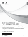
LG ATNQ24GNLE1 is a 4-way ceiling cassette air conditioner that offers efficient cooling and heating solutions for residential and commercial spaces. With its sleek design and powerful performance, this air conditioner is an ideal choice for those seeking comfort and energy efficiency.
LG ATNQ24GNLE1 is a 4-way ceiling cassette air conditioner that offers efficient cooling and heating solutions for residential and commercial spaces. With its sleek design and powerful performance, this air conditioner is an ideal choice for those seeking comfort and energy efficiency.


-
 1
1
-
 2
2
-
 3
3
-
 4
4
-
 5
5
-
 6
6
-
 7
7
-
 8
8
-
 9
9
-
 10
10
-
 11
11
-
 12
12
-
 13
13
-
 14
14
-
 15
15
-
 16
16
-
 17
17
-
 18
18
-
 19
19


LG ATNQ24GNLE1 Installation guide
- Category
- Mobile air conditioners
- Type
- Installation guide
- This manual is also suitable for
LG ATNQ24GNLE1 is a 4-way ceiling cassette air conditioner that offers efficient cooling and heating solutions for residential and commercial spaces. With its sleek design and powerful performance, this air conditioner is an ideal choice for those seeking comfort and energy efficiency.
Ask a question and I''ll find the answer in the document
Finding information in a document is now easier with AI
Related papers
-
LG ATNQ24GNLE3.ANWBEVN Installation guide
-
LG ATNQ18GPLE3 Owner's manual
-
LG ATNW60GYLP0 Installation guide
-
LG AMNW18GTQA1 Installation guide
-
-
LG ATNQ18GPLE5.EMFBEVH Owner's manual
-
-
LG LCN429HV Installation guide
-
LG LCN428HV Installation guide
-
LG LCN098HV4 Installation guide