
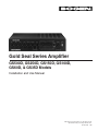
Gold Seal Series Amplifier
GS500D, GS250D, GS150D, GS100D,
GS60D, & GS35D Models
Installation and Use Manual
© 2016 Bogen Communications, Inc. All rights reserved.
Specifications subject to change without notice.
54-2229-01D 1605

CAUTION: DO NOT INSTALL OR PLACE THIS UNIT IN A BOOKCASE, BUILT-IN CABINET, OR IN ANOTHER
CONFINED SPACE. ENSURE THE UNIT IS WELL VENTILATED. TO PREVENT THE RISK OF SHOCK OR FIRE
FIRE HAZARD DUE TO OVERHEATING, ENSURE THAT CURTAINS AND ANY OTHER MATERIALS DO NOT
OBSTRUCT THE VENTILATION VENTS.
Always follow these basic safety precautions when installing and using the unit:
IMPORTANT SAFETY INSTRUCTIONS
1. Read these instructions.
2. Keep these instructions.
3. Heed all warnings.
4. Follow all instructions.
5. Do not use this apparatus near water.
6. Clean unit with dry cloth.
7. Do not block any ventilation openings. Install in accordance with the manufacturer's instructions.
8. Do not install near any heat sources such as radiators, heat registers, stoves, or other apparatus
(including amplifiers) that produce heat.
9. Do not defeat the safety purpose of the polarized or grounding-type plug. A polarized plug has two blades
with one wider than the other. A grounding-type plug has two blades and a third grounding prong. The
wide blade, or the third prong, are provided for your safety. If the provided plug does not fit into your
outlet, consult an electrician for replacement of the obsolete outlet.
10. Protect the power cord from being walked on or pinched particularly at plugs, convenience receptacles,
and the point where they exit from the apparatus.
11. Only use attachments/accessories specified by the manufacturer.
12. Unplug this apparatus during lightning storms or when not used for long periods of time.
13. Refer all servicing to qualified service personnel. Servicing is required when the apparatus has been
damaged in any way, such as power-supply cord or plug is damaged, liquid has been spilled o robjects
have fallen into the apparatus, the apparatus has been exposed to rain or moisture, does not operate
normally, or has been dropped.
CAUTION: TO PREVENT THE RISK OF ELECTRIC SHOCK, DO NOT REMOVE ANY
FRONT/BACK COVERS OR PANELS. NO USER-SERVICEABLE PARTS INSIDE.
REFER SERVICING TO QUALIFIED PERSONNEL.
The exclamation point within an equilateral triangle is intended to alert the user to the presence of
important operating and maintenance (servicing) instructions.
The lightning flash with arrowhead symbol, within an equilateral triangle, is intended to alert the user
to the presence of uninsulated "dangerous voltage" within the product's enclosure that may be of
sufficient magnitude to constitute a risk of electric shock to persons.
WARNING: To reduce the risk of fire or electric shock, do not expose this apparatus to rain or moisture.
Avertissement: pour réduire le risque d’incendie ou de choc électrique, ne pas exposer cet appareil sous la pluie
et l’humidité.
The apparatus shall not be exposed to dripping or splashing and that no objects filled with liquids, such as
vases, shall be placed on apparatus.
L'appareil ne doit pas être exposé aux écoulements ou aux éclaboussures et aucun objet ne contenant de liquide,
tel qu'un vase, ne doit être placé sur l'objet.
The mains plug is used as disconnect device. The mains plug of apparatus should not be obstructed OR
should be easily accessed during intended use. To be completely disconnect the power input, the mains
plug of apparatus shall be disconnected from the mains.
La prise du secteur est utilisé pour déconnecter le système. La prise du secteur ne doit pas être obstruée ou doit
être facilement accessible pendant son utilisation. Pour être complètement déconnecté de l’alimentation d’entrée,
la prise doit être débranchée du secteur

Contents
Introduction . . . . . . . . . . . . . . . . . . . . . . . . . . . . . . . . . . . . . . . . . . . . . . . . . . . . . .1
Features . . . . . . . . . . . . . . . . . . . . . . . . . . . . . . . . . . . . . . . . . . . . . . . . . . . . . .1
Packing Contents . . . . . . . . . . . . . . . . . . . . . . . . . . . . . . . . . . . . . . . . . . . . . . .1
Accessories . . . . . . . . . . . . . . . . . . . . . . . . . . . . . . . . . . . . . . . . . . . . . . . . . . .1
Panel Descriptions . . . . . . . . . . . . . . . . . . . . . . . . . . . . . . . . . . . . . . . . . . . . . .2-3
Front Panel . . . . . . . . . . . . . . . . . . . . . . . . . . . . . . . . . . . . . . . . . . . . . . . . . . .2
Rear Panel . . . . . . . . . . . . . . . . . . . . . . . . . . . . . . . . . . . . . . . . . . . . . . . . . . .3
Input Connections . . . . . . . . . . . . . . . . . . . . . . . . . . . . . . . . . . . . . . . . . . . . . . .4-5
MIC 1-4 . . . . . . . . . . . . . . . . . . . . . . . . . . . . . . . . . . . . . . . . . . . . . . . . . . . . . .4
MIC 5/TEL . . . . . . . . . . . . . . . . . . . . . . . . . . . . . . . . . . . . . . . . . . . . . . . . . . . .4
MIC 6/AUX 1 . . . . . . . . . . . . . . . . . . . . . . . . . . . . . . . . . . . . . . . . . . . . . . . . . .4
AUX 2 . . . . . . . . . . . . . . . . . . . . . . . . . . . . . . . . . . . . . . . . . . . . . . . . . . . . . . . .4
Phantom Power for MIC 5 & MIC 6 . . . . . . . . . . . . . . . . . . . . . . . . . . . . . . . . .5
Remote Volume Control . . . . . . . . . . . . . . . . . . . . . . . . . . . . . . . . . . . . . . . . . .5
Precedence Connections . . . . . . . . . . . . . . . . . . . . . . . . . . . . . . . . . . . . . . . . .5
Output Connections . . . . . . . . . . . . . . . . . . . . . . . . . . . . . . . . . . . . . . . . . . . . . . .6
Output Terminal Strip . . . . . . . . . . . . . . . . . . . . . . . . . . . . . . . . . . . . . . . . . . . .6
WMT1A . . . . . . . . . . . . . . . . . . . . . . . . . . . . . . . . . . . . . . . . . . . . . . . . . . . . . .6
To Power Amp . . . . . . . . . . . . . . . . . . . . . . . . . . . . . . . . . . . . . . . . . . . . . . . . .6
Pre-Out/Power In Jack . . . . . . . . . . . . . . . . . . . . . . . . . . . . . . . . . . . . . . . . . . .6
Tape Out . . . . . . . . . . . . . . . . . . . . . . . . . . . . . . . . . . . . . . . . . . . . . . . . . . . . . .6
Operation . . . . . . . . . . . . . . . . . . . . . . . . . . . . . . . . . . . . . . . . . . . . . . . . . . . . . .7-9
Power Switch . . . . . . . . . . . . . . . . . . . . . . . . . . . . . . . . . . . . . . . . . . . . . . . . . .7
Individual Volume Controls . . . . . . . . . . . . . . . . . . . . . . . . . . . . . . . . . . . . . . .7
Lo-Cut Filter . . . . . . . . . . . . . . . . . . . . . . . . . . . . . . . . . . . . . . . . . . . . . . . . . . .7
Contour Switch . . . . . . . . . . . . . . . . . . . . . . . . . . . . . . . . . . . . . . . . . . . . . . . . .7
Audio Enhancement . . . . . . . . . . . . . . . . . . . . . . . . . . . . . . . . . . . . . . . . . . . . .7
Dual-Function Acoustic Equalizer . . . . . . . . . . . . . . . . . . . . . . . . . . . . . . . . . .8
Acoustic Shaping Mode . . . . . . . . . . . . . . . . . . . . . . . . . . . . . . . . . . . . . . . . . .8
Feedback Control Mode . . . . . . . . . . . . . . . . . . . . . . . . . . . . . . . . . . . . . . . . . .8
Telephone Paging Controls & Settings . . . . . . . . . . . . . . . . . . . . . . . . . . . . . .8
ALC . . . . . . . . . . . . . . . . . . . . . . . . . . . . . . . . . . . . . . . . . . . . . . . . . . . . . . . . .9
VOX . . . . . . . . . . . . . . . . . . . . . . . . . . . . . . . . . . . . . . . . . . . . . . . . . . . . . . . . .9
Variable Mute . . . . . . . . . . . . . . . . . . . . . . . . . . . . . . . . . . . . . . . . . . . . . . . . . .9
Troubleshooting . . . . . . . . . . . . . . . . . . . . . . . . . . . . . . . . . . . . . . . . . . . . . . . . .10
Technical Specifications . . . . . . . . . . . . . . . . . . . . . . . . . . . . . . . . . . . . . . . . . .11
Limited Warranty; Exclusion of Certain Damages . . . . . . . . . . . . . . . . . . . . . .12

This page intentionally left blank.

The Bogen Gold Seal Series amplifiers were designed with the sound contractor in mind. They provide unparalleled
flexibility and versatility, without the need for add-on modules.
Unlike other typical amplifier lines, the professional sound contractor need not purchase a higher-powered amplifier
just to get more extensive features or flexibility. Each of the Gold Seal Series amplifier models incorporate the exact
same set of features – from 35 watts up to 500 watt models.
In addition to its extensive input flexibility, the Gold Seal D-Series amplifiers offer a combination of features not found
in any other commercial amplifier.
Features
Packing Contents
1 - Gold Seal Series D Amplifier
1 - User Manual
Accessories
The following accessories are available for your Gold Seal D-Series Amplifier at additional cost:
• Model GSTRC — A plexiglass cover to protect control settings
• Model GSDRPK — Rack mounting installation kit
• Model GSRVC — From distances up to 1000 feet away from the amplifier, this remote volume
control adjusts the volume of the amplifier
• Model WMT1A — Balanced Line Output Transformer
Introduction
1
• 4 Dedicated microphone inputs (XLR connectors)
• 1 Selectable MIC/TEL input
• 1 Selectable MIC/AUX input
• 1 Dedicated AUX input
• 4-Ohm, 8-ohm, 25V, 25VCT, and 70V transformer-
coupled outputs
• 150W, 250W and 500W models
• Rack mountable – 2RU package for all models
• Dual-function 10-band graphic equalizer (Acoustic
EQ/Feedback Control)
• True loudness contour function
• Audio Enhancement feature for improved intelligibility
• Switchable phantom power
• Variable AUX input muting
• Remote master volume control capability
• Input muting via contact on all inputs
• Voice-activated AUX muting on TEL input
• Automatic level control on TEL input
• AUX fade back after TEL page
• Preamp out/Power amp in connections
• Booster amp output connection
• Tape output connection
• Balanced line driver output (using WMT1A accessory)
• Lo-cut filter for MIC channels
• Available tamper-resistant front cover (GSTRC)
• Available rack mounting kit (GSDRPK)
• Available remote volume control (GSRVC)

Panel Descriptions
2
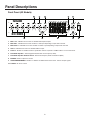
Front Panel (All Models)
1. MIC 1 to 4 - Individual level controls for dedicated microphone inputs.
2. MIC 5/TEL - Individual level control for MIC 5 or TEL input depending on input mode selected.
3. MIC 6/AUX 1 - Individual level control for MIC 6 or AUX 1 input depending on input mode selected.
4. AUX 2 - Individual level control for dedicated AUX 2 input.
5. Contour - Enables or disables loudness equalization. Affects only AUX 2 and MIC 6/AUX 1 if set in AUX mode.
6. Dual Mode Equalizer - 10 band graphic EQ with dual center frequency ability.
7. Dual Mode Equalizer Selector Switch - Selects EQ frequency bands or EQ defeat (OUT).
8. MASTER - Master output level control.
9. AUDIO ENHANCEMENT - Enables or disables the Audio Enhancement effect. Affects all input signals.
10. POWER - AC Power switch.

Panel Descriptions
3
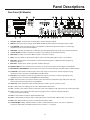
Rear Panel (All Models)
1. Amplifier Output - Terminal strip containing all the Gold Seal speaker outputs.
2. WMT1A - RCA connection for (Bogen model WMT1A) 600-ohm balanced line-matching transformer output.
3. TO PWR AMP - RCA connection provides a low impedance, unbalanced signal level output as a feed to high
impedance inputs of other external amplifiers.
4. VAR MUTE - 4 Switch selectable levels of AUX input signal muting during TEL page (works only in the TEL input mode).
5. LO CUT FILTER - Enables or disables low frequency roll off (65 Hz) for all microphone inputs.
6. MIC 6/AUX 1 - Switch selects either MIC 6 or AUX 1 connections as input.
7. MIC 6 - Screw terminals for balanced microphone (active only when AUX 1/MIC 6 switch is set to MIC 6).
8. MIC 5/TEL - Dual-function screw terminals for either balanced microphone or 600-ohm balanced input from
telephone page port.
9. MIC 5/TEL - Switch selects mode of operation for MIC 5/TEL input.
10. REMOTE MSTR - Screw terminal pair for connection of remote master volume control (Bogen model GSRVC).
11. MIC/AUX/TEL PRECEDENCE - Screw terminal connections that allow externally controlled muting of individual inputs.
12. POWER IN - RCA unbalanced direct input to power amp stage for connection to external signal processing
equipment (used in conjunction with PRE OUT and LINK switch).
13. PRE OUT - RCA unbalanced output from preamp/mixer stage for connection to external signal processing
equipment (used in conjunction with POWER IN and LINK switch).
14. LINK - Switch that makes or breaks the internal connection between preamp/mixer stage and power amp stage
when used with external signal processing equipment.
15. TAPE OUT - RCA unbalanced output, pre-EQ and master volume. (Post Lo-Cut filter, see #5).
16. AE - Variable control for adjusting the amount of Audio Enhancement effect.
17. ALC - Variable control adjusts amount of Automatic Level Control applied to TEL input (works only in TEL input mode).
18. VOX - Variable control adjusts TEL input signal level trigger point for automatic muting of AUX input
(works only in TEL input mode).
19. AUX 2 - RCA unbalanced input for dedicated AUX 2 input.
20. AUX 1 - RCA unbalanced input for AUX 1 input signal (works only when AUX 1/MIC 6 switch is set to AUX 1).
21. MIC 1 to 4 - Balanced XLR connectors for dedicated microphone inputs.
22. PHANTOM (MIC 1 to 4) - Individual switches enable or disable phantom power to each of the 4 dedicated
microphone inputs (MIC 5 and MIC 6 phantom power selection — see page 5).

Input Connections
4
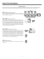
MIC 1- 4 (Rear Panel; #21 and #22)
MIC 1 through 4 utilize female XLR-type microphone connectors. A slide
switch located above each XLR connector is used to supply phantom
power for condenser microphones.
MIC 5/TEL (Rear Panel; #8 and #9)
The MIC 5/TEL input is designed to accept input from a microphone or
from a telephone line. A slide switch is provided to select MIC 5 or TEL
input. To connect a microphone, place the MIC 5/TEL switch in the MIC
position. Use two conductor shielded cable and connect the cable shield
to the center GND terminal. To use the TEL input, place the MIC 5/TEL
switch in the TEL position and connect the 600-ohm telephone paging
source (dry signal only - no DC voltage) to the MIC 5/TEL screw terminals.
See page 5 for Phantom Power for MIC 5.
MIC 6/AUX 1 (Rear Panel; #6, #7, #20)
The MIC 6/AUX 1 input is designed to accept input from a microphone
using terminal strip connections or from a high level auxiliary source such
as a tuner or CD player using the AUX 1 RCA jack. A slide switch is used
to select input type. Connect a microphone to the screw terminals labeled
MIC 6 (works only when AUX 1/MIC 6 switch is in the MIC 6 position).
Use two conductor shielded cable and connect the cable shield to the
center GND terminal. Connect an auxiliary input source to the AUX 1
RCA jack (only works when the AUX 1/MIC 6 switch is in the AUX1
position.) See page 5 for Phantom Power for MIC 6.
AUX 2 (Rear Panel; #19)
The AUX 2 input uses an RCA plug and accepts input from a dedicated
AUX source
.
Installation Note
Keep input leads away from the output leads and AC power cables. Unless the driving source provides a low-impedance output,
keep the input lead under ten feet in length. Make all connections to the unit with the POWER switch in the OFF position
1 — GND
2 — +
3 — –

Input Connections
5
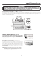
Remote Volume Control (Rear Panel; #10)
If remote volume control is desired, connect the Bogen accessory GSRVC
Remote Volume Control to the screw terminals marked REMOTE MSTR.
Wire length can be up to 1000 feet using 22-gauge wire. Connections are
not polarity sensitive.
Precedence Connections (Rear Panel; #11)
Precedence connections allow any combination of inputs to be completely
muted with a contact closure. Closing a contact across any of the prece-
dence terminals and the PREC COM 1 terminal will mute that input.
A customer-supplied normally-open SPST switch, push-to-talk switch,
microphone switch, relay or telephone system contact can be used to
provide the closure.
Note: Activating the precedence control for AUX inputs completely
mutes the input signal. The VAR MUTE control has no effect
when muting inputs using precedence control.
Phantom Power for MIC 5 & MIC 6 (Inside Unit)
A single internal jumper is provided to supply phantom power to both MIC 5 and MIC 6. The amplifier is shipped with the jumper in
the OFF position. Place Jumper across “ON” Pins to apply Phantom Power to both MIC 5 and MIC 6. See the figure below for the
location of the phantom power jumper.
JP1
R152
C25
C91
MIC3R26
Q1
JP1
JP1
ON
OFF
MIC5 MIC6
PHANTOM POWER
STANDARD
MIC 5 and MIC 6
Input Terminal Strip
WARNING
Removal of the amplifier cover exposes internal components and presents an electrical shock hazard. For this
reason, do not perform any functions requiring removal of the cover of the amplifier unless you are qualified to
do so. Always disconnect AC power from the unit before attempting to remove the cover.
ABOVE
VIEW

Output Connections
6
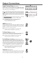
WMT1A (Rear Panel; #2)
This RCA output jack, when used with a Bogen WMT1A Line-Matching
Transformer accessory provides a 600-ohm output to feed a remote
amplifier or a telephone line. Refer to the instructions provided with the
WMT1A accessory for connection information.
Note: Shorting clip between GND/COM on the speaker output
terminals strip must be installed to use this feature.
To Power Amp (Rear Panel; #3)
The Gold Seal Series amplifier may be used to drive an external power am-
plifier (can only be used with unbalanced high-impedance inputs).
Note: Shorting clip between GND/COM on the speaker output
terminal strip must be installed to use this feature.
Pre-Out/Power In Jacks (Rear Panel; #12, #13, #14)
These jacks permit the insertion of signal processing equipment into the
signal path between the preamp output and the power amp input. The
LINK switch should be in the IN position for normal operation. When using
external signal processing equipment, place the switch in the OUT posi-
tion and connect PRE OUT to the signal processing equipment’s input.
Connect the POWER IN to the signal processing equipment’s output.
Note: Ensure that the LINK switch is in the IN position when NOT
using external signal processing equipment, otherwise there
will be no output from the amplifier.
Tape Out (Rear Panel; #15)
The TAPE OUT jack provides a line-level output to feed a recording
device. The output is not effected by the Master volume control or EQ,
however, the output is affected by the microphone inputs’ Lo-Cut filter.
Output Terminal Strip (Rear Panel; #1)
Speaker systems are connected directly to the speaker output terminals
on the rear panel. Connect one speaker lead to the COM terminal and the
other to the terminal corresponding to the impedance of the speaker
system. Select only one of the output types.
For ALL
ground-referenced output operations (unbalanced systems),
install a shorting clip (18 AWG solid wire jumper) between COM and
GND. Installing this shorting clip will also reduce the potential for the
amplifier going into protection when the input signals and/or the gain set
are too high.
For special applications only
that require floating outputs (i.e., balanced
systems), do not install a shorting clip between COM and GND.
Note: If GND/COM shorting clip is not installed, the WMT1A
and “TO PWR AMP” outputs will not operate.
CLASS 2 WIRING SHALL BE USED
Shorting Clip: 18 AWG solid wire jumper

Operation
7
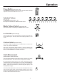
Power Switch (Front Panel; #10)
The POWER switch applies power to the unit. Above the switch is an LED
light which will illuminate RED when power is on.
Individual Volume
Controls (Front Panel; #1– #4)
Each input is controlled by an individual volume control.
Master Volume Control (Front Panel; #8)
The overall volume is controlled by the MASTER volume control.
Lo-Cut Filter (Rear Panel; #5)
The Lo-Cut filter on the rear panel provides low-frequency attenuation on
the microphone inputs. This helps reduce mic breath pop, wind noise, and
rumble.
Contour Switch (Front Panel; #5)
This switch enables or bypasses the variable loudness contour. This
feature only effects the AUX inputs.
This feature is designed to improve richness of sound by restoring the
high and low frequencies that the ear is insensitive to at low volume
levels. The effect diminishes as volume is increased.
Audio Enhancement
(Front Panel; #9 / Rear Panel; #16)
The front panel Audio Enhancement switch enables or bypasses the Audio
Enhancement feature. This feature effects all inputs when enabled.
By regenerating the upper harmonics, this audio enhancement system
recreates the presence and realism that is lost in the audio amplification
process. This results in increased presence and clarity, increased intelli-
gibility, greater perceived loudness (without using extra power), and
reduced listener fatigue.
The rear panel AE adjustment controls the mix of the Audio Enhancement
effect with the audio signal. Counterclockwise rotation of the control
minimizes the Audio Enhancement effect. Clockwise rotation of the control
maximizes the Audio Enhancement effect.

Operation
8
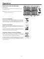
Dual-Function Acoustic Equalizer
(Front Panel; #6)
The unique dual-function equalizer can be used for acoustic shaping
or for feedback control.
Note: When the switch is placed in the OUT position, the equalizer
is bypassed for a flat response.
Acoustic Shaping Mode
When the switch is set in the ACOUSTIC EQ position, full range equal-
ization (10 bands on 1 octave centers starting at 62.5 Hz) is provided with
a boost/cut of 12 dB. In this mode, the equalizer can be used to compen-
sate for room acoustics, or to satisfy the listening preference of the user.
Feedback Control Mode
When the switch is placed in the FEEDBACK CONTROL position, the
equalizer can be used to reduce feedback and increase the effective gain
of the system.
In feedback control mode, the equalizer provides increased control of
frequencies between 125 Hz and 8 kHz. The 10 bands are located on 2/3
octave centers with 12 dB cut/boost on each band.
Telephone Paging Controls & Settings
The MIC 5/TEL volume control on the front panel controls the volume
of the telephone paging input when the control is set to the TEL mode
(See page 4 for information on setting the TEL input mode).
The TEL input mode uses voice-activated muting for the AUX inputs and
automatic level control for providing constant paging level. To optimize
TEL input performance, both the ALC control and the VOX threshold may
need to be adjusted.

Operation
9
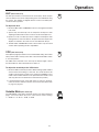
ALC (Rear Panel; #17)
The TEL input features an automatic level control (ALC) which compen-
sates for different voice levels and speaking styles of the individuals using
the system. The amplifier is shipped with this control in the OFF (max.
counterclockwise) position.
To adjust the ALC:
1. Rotate the MIC 5/TEL and MASTER controls to the highest level likely
to be used.
2. Speak softly and distinctly into the telephone mouthpiece while
adjusting the MIC 5/TEL volume control to the desired output level.
3. Speak in a loud voice directly into the telephone mouthpiece while
rotating the ALC control clockwise to the point where the output of the
amplifier is reduced to the same level as that obtained in Step 2.
4. The MIC 5/TEL and MASTER controls can be used to vary the overall
volume without upsetting the ALC adjustm
ent.
VOX (Rear Panel; #18)
The telephone page input features voice-activated AUX muting. This feature
always mutes AUX 2 and only mutes AUX 1 when the AUX1/MIC 6 switch
is set in that position.
The VOX control should be set so that only the desired signal is above
the threshold level, while unwanted noise is below it.
To adjust the sensitivity of the VOX circuit:
1. Rotate the VOX control fully clockwise. While making a public address
announcement and talking at a low level, the sound should not be
choppy or missing parts of words. If it is choppy or intelligibility is poor,
rotate control counterclockwise to the point where the sound is clear
and crisp (but not to the maximum counterclockwise position).
2. If the background music shuts down when no page is in progress,
rotate the control clockwise until the music will not shut down when
no page is in progress.
Variable Mute (Rear Panel; #4)
The VAR MUTE control mutes the AUX input(s) only during telephone
pages. The control allows the user to select from 4 levels of muting:
1 = -60 dB, 2 = -21 dB, 3 = -10 dB, 4 = 0 dB.

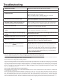
Troubleshooting
10
Check the fuse. Replace fuse only with same type and rating.
Make sure that the speaker output GND/COM shorting clip is in place.
Make sure that the MIC 5/TEL switch is in the TEL position.
Make sure the VOX control is set properly
When connecting the telephone Tip & Ring, make sure to use the two
outside terminals and not the center terminal (GND).
Check that the VAR MUTE control is not set to 4 (0 dB). This control adjusts the
level of the background music when making a page. See page 9.
Check your wiring connections for the 3-pin connector. Pin 1 is the shield con-
nection. Pins 2 and 3 connect to the balanced signal leads on the mic cable.
Make sure that phantom power switch (MIC 1 - 4) is on. See page 4.
MIC 5 and 6 use circuit board jumper. See page 5.
Adjust the VOX control on the rear panel to eliminate any unwanted noise that
may be triggering the VAR MUTE circuit. See page 9.
Adjust the VOX control counterclockwise to make the trigger activate at a lower
input signal level. See page 9.
Adjust the ALC control on the rear panel. See page 9.
Make sure MIC 6/AUX 1 switch is in the AUX 1 position.
Make sure the signal source is plugged into the AUX 1 RCA jack.
Class-D amplifiers have built-in protection to prevent overloading which may
damage circuitry and/or connected speakers. (See explanation below for details.)
Make sure the MIC / AUX / TEL input signals do not exceed specifications.
Lower the gain on the MIC / AUX / TEL inputs using the front panel adjustment
knobs and/or lower the Master Volume using the front panel adjustment knob.
Install a shorting clip between COM and GND, as per recommendations
on Page 6 “Output Connections”.
Amplifier will not turn ON.
No output on WMT1A and Power Amp Outputs.
No telephone output.
AUX Input will not mute with telephone page.
Microphone squeals or hums when using the 3-pin
connectors but not when using screw terminals.
Condenser MIC will not work.
Telephone input cuts off the music when not making
a page.
Telephone input is choppy or cuts off the beginning
of a page.
The telephone page volume is too loud on some pages.
AUX 1 Input not working.
Amplifier temporarily goes into protection mode.
AND/OR
Sound output to speakers cuts-out momentarily.
Class-D Audio Amplifier Full-Power Clipping and Self-Protection Explained
Class-D audio amplifiers operate on a completely different principal than legacy Class A-B amplifiers. To distinguish and understand the differences
as they relate to full-power clipping and protection, some review is in order.
A short review of Class A-B operation and self-protection
Legacy Class A-B audio amplifiers are ‘linear’ amplifiers and if driven past their power limits will ‘clip’ the output signal. When this occurs the amplifier
simply can’t draw enough current from the AC wall receptacle to produce the output audio waveform as a ‘likeness’, of the input signal. The term ‘clip’
arises from the output signal waveform having a ‘clipped-off’ appearance, or a straight-line appearing across the output waveform. If the input audio
signal voltage continues to be increased by the user (by turning up the volume control), the amplifier will protect itself by opening or blowing its AC
line fuse, or engaging some other equally protective device. Output signal clipping is heard as a highly distorted signal from the speakers, and in
many cases damaging the speakers too.
Class-D audio amplifier operation and self-protection
Class-D amplifiers are becoming the norm for audio amplifier applications because of their overall performance in audio reproduction, smaller physical
size and improved energy efficiency.
The basic operating principles behind Class-D amplifiers operating requires active logic controls to be employed that monitor input and output wave-
forms. Rather than allowing the output waveform to clip and possibly damage speakers, the amplifier has built-in self-protection circuitry which simply
turns off the amplifier integrated control circuit. The end-result is silence, also colloquially known as a “hole-in the audio”. The audio output to the
speaker(s) will simply shut-off until the amplifier’s internal protection is relieved of this overload condition. This behavior is intrinsic to Class-D amplifiers
and is considered normal operation. This effect is minimized/avoided by properly configuring an audio system within its performance limits.

Technical Specifications
11
Power Rating (RMS):
GS35D:
35 watts;
GS60D:
60 watts;
GS100D:
100 watts;
GS150D:
150 watts;
GS250D:
250 watts;
GS500D:
500 watts
Frequency Response:
Transformer Output:
65 Hz to 20 kHz, +0/-2 dB @ -2 dB
Distortion:
Transformer Output:
0.5% (max.), 0.3% (typ.), 65 Hz to 20 kHz
Signal-to-Noise Ratio:
Fundamental:
-70 dB or better; AUX 1 & 2: -70 dB; Tel: -70 dB or better @ 600 ohms
MIC 1 through MIC 6:
-60 dB or better @ 200 ohms
Inputs/Outputs:
MIC:
6 Lo-Z balanced via 4 XLR connectors and 2 screw terminals.
Sensitivity:
11mV (200 ohms)
AUX:
2 Hi-Z RCA jacks. Sensitivity: 0.085V (10k ohms)
Telephone:
Screw terminals. Sensitivity: 0.07V (600 ohms)
Output to Power Amp:
5V @ Rated Output via RCA jack
Power In/Pre Out:
In 1V/Out 1V via RCA jacks
WMT1A Output:
25V @ Rated Output via RCA jack
Tape Output:
700 mV @ Rated Output via RCA jack
Output Impedance: All models: balanced or unbalanced 4-ohm, 8-ohm, 25V, 25VCT, 70V
Output Regulation: Better than 2 dB from no load to full load
AC Input Voltage: 120V~ 60 Hz
AC Current:
GS35D:
0.8A;
GS60D:
1.3A;
GS100D:
2.1A;
GS150D:
2.5A;
GS250D:
4.0A;
GS500D:
6.5A
Thermal Emissions (Full Power):
GS35D:
78.5 BTU/HR.;
GS60D:
119.5 BTU/HR.;
GS100D:
191.3 BTU/HR.;
GS150D:
136.6 BTU/HR.;
GS250D:
239.1 BTU/HR.;
GS500D:
467.9 BTU/HR.
Variable Mute Range: -60, -21, -10, 0 dB (AUX1 & 2)
ALC: Distortion: less than 0.5%; Compression: 25 dB (TEL)
VOX Threshold: TEL Input 20 mV (VOX control max. CW position)
MIC Precedence: Via terminal strip. -60 dB: MIC 1, 2, 3, 5/TEL, 6/AUX, AUX 2
Power In/Pre Out: In 1V/Out 1V via RCA jacks
Phantom Power: 13V DC
Lo-Cut: 3 dB@100 Hz
Loudness Contour: +8 dB @ 100 Hz, +4 dB @ 10 kHz (AUX 1 & 2 control at 1/4 CW position)
Overload Protection: Electronic with automatic reset
Thermal Protection: Thermistor attached to heat sink
Dimensions: 16-1/2" W x 3-1/2" H x 13-1/2" D
Shipping Weight:
GS35D:
13.5 lb.;
GS60D:
14.3 lb.;
GS100D:
16.4 lb;
GS150D:
18.5 lb.;
GS250D:
19.5 lb.;
GS500D:
26.5 lb

Limited Warranty; Exclusion of Certain Damages
Bogen's Gold Seal Series amplifiers are warranted to be free from defects in material or workmanship for three (3) years from the date of
sale to the original purchaser. Any part of any Bogen product covered by this warranty that, with normal installation and use, becomes
defective (as confirmed by Bogen upon inspection) during the applicable warranty period, will be repaired or replaced by Bogen, at Bogen’s
option, provided the product is shipped insured and prepaid to: Bogen Factory Service Department, 4570 Shelby Air Drive, Suite 11,
Memphis, TN 38118 USA. Repaired or replacement product will be returned to you freight prepaid. This warranty does not extend to any
of our products that have been subjected to abuse, misuse, improper storage, neglect, accident, improper installation or have been modified
or repaired or altered in any manner whatsoever, or where the serial number or date code has been removed or defaced.
THE FOREGOING LIMITED WARRANTY IS BOGEN’S SOLE AND EXCLUSIVE WARRANTY AND THE PURCHASER’S SOLE AND
EXCLUSIVE REMEDY. BOGEN MAKES NO OTHER WARRANTIES OF ANY KIND, EITHER EXPRESS OR IMPLIED, AND ALL
IMPLIED WARRANTIES OF MERCHANTABILITY OR FITNESS FOR A PARTICULAR PURPOSE ARE HEREBY DISCLAIMED AND
EXCLUDED TO THE MAXIMUM EXTENT ALLOWABLE BY LAW. Bogen's liability arising out of the manufacture, sale or supplying of
products or their use or disposition, whether based upon warranty, contract, tort or otherwise, shall be limited to the price of the product.
IN NO EVENT SHALL BOGEN BE LIABLE FOR SPECIAL, INCIDENTAL OR CONSEQUENTIAL DAMAGES (INCLUDING, BUT NOT
LIMITED TO, LOSS OF PROFITS, LOSS OF DATA OR LOSS OF USE DAMAGES) ARISING OUT OF THE MANUFACTURE, SALE
OR SUPPLYING OF PRODUCTS, EVEN IF BOGEN HAS BEEN ADVISED OF THE POSSIBILITY OF SUCH DAMAGES OR LOSSES.
Some States do not allow the exclusion or limitation of incidental or consequential damages, so the above limitation or exclusion may not
apply to you. This warranty gives you specific legal rights, and you may also have other rights which vary from State to State.
Products that are out of warranty will also be repaired by the Bogen Factory Service Department -- same address as above or call
201-934-8500. The parts and labor involved in these repairs are warranted for 90 days when repaired by the Bogen Factory Service
Department. All shipping charges in addition to parts and labor charges will be at the owner's expense. All returns require a Return Author-
ization number. For most efficient warranty or repair service, please include a description of the failure.
Products manufactured and labeled by other companies may be covered by warranties offered by such companies. Please call Bogen
Customer Service or refer to product packaging for manufacturer’s warranty for non-Bogen branded products.
11/2014
www.bogen.com
-
 1
1
-
 2
2
-
 3
3
-
 4
4
-
 5
5
-
 6
6
-
 7
7
-
 8
8
-
 9
9
-
 10
10
-
 11
11
-
 12
12
-
 13
13
-
 14
14
-
 15
15
-
 16
16


Ask a question and I''ll find the answer in the document
Finding information in a document is now easier with AI
Related papers
-
Bogen GS35, GS60, GS100, GS150, GS250 User manual
-
-
Bogen DS3 Datasheet
-
-
Bogen TPU600-G2 User guide
-
Bogen MT300M User guide
-
-
-
-
Other documents
-
Peavey MA Series Module MPE-SO Owner's manual
-
OSD Audio PAM245 User manual
-
Electro-Voice MA-606 User manual
-
Rolls RPB488 User manual
-
TOA A-706 User manual
-
Avaya Bogen Single-Zone Paging Microphone User manual
-
 Wheelock TPA-100-B Specification
-
PyleHome PT610 User manual
-
-
Paso T3015DMA Installation Manual And Operating Instructions
