Shindaiwa DGW500DM-S1 User manual
- Category
- Welding System
- Type
- User manual

OWNER
’
S AND OPERATOR
’
S MANUAL
Vertical, Water-Cooled 4-Cycle Diesel Engine
DGW500DM-S1
X753-007 08 0
X753803-230 0
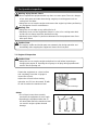
CAUTION
Do not operate the Generator/Welder, or any other appliance, before you have
read and understood the instructions
for use and keep near for read
y use.


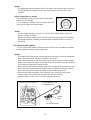
Introduction
We would like to thank you very much for purchasing this Shindaiwa Sound proof
Diesel Engine Generator & Welder.
• This manual has been created in order to ensure safe and proper use of this
equipment. Be sure to thoroughly read this manual before operating the equipment
as the improper operation of this equipment can result in an accident or
malfunction.
• This equipment should only be operated by persons who thoroughly understand the
contents of this manual and can safely operate the equipment. Persons who are ill,
taking medicine, or are in bad health should not operate this equipment if such
conditions will affect operation of the equipment and related work.
• Operation and use of this equipment must be in strict compliance with the
applicable laws, as well as rules and regulations based on such laws.
• Always be sure to include this manual with the equipment if it is loaned out to
another party, and instruct said party that they must thoroughly read this manual
before operating the equipment.
• Store this manual securely in a predetermined location so that it can be readily
accessed at all times to order parts or arrange for repair. Contact the retail outlet
where this equipment was purchased if any parts are lost, the equipment becomes
soiled, or is otherwise damaged in any manner.
• Consult with the retail outlet where the equipment was purchased if any of the
points are unclear or you would like further information.
Be sure to note the model name and serial number of your equipment, and provide
this information when making an inquiry.
• If disposing of this equipment, dispose in a manner according to laws and
regulations applicable to industrial waste. Consult with the retail outlet where the
equipment was purchased if you have any inquiries regarding proper disposal.
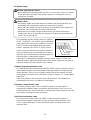
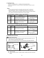
■The precautions used in this manual are divided into the following three ranks.
• It is possible that items described under < Caution >
or <Note>
can result in a
serious accident depending on the circumstances. The contents of both of these
types of precautions are important. Be sure to always comply with all precautions.
Warning:Improper operation can result in death or serious personal injury.
Caution:Improper operation can result in moderate or minor personal injury, or
physical damage.
<Note> :Explanatory note in order to ensure that equipment protection and
performance are fully realized.

- 1 -
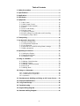
Table of Contents
1. Safety Precautions ........................................................................ 2
2. Specifications ................................................................................ 6
3. Applications ................................................................................... 7
4. Part Names ..................................................................................... 7
5. Equipment .................................................................................... 10
5-1. Idle Control .......................................................................... 10
5-2. Weld Output Control ............................................................ 10
5-3. Remote Control (Option) ..................................................... 11
5-4. Meter ................................................................................... 12
5-5. Error Code Display .............................................................. 12
5-6. Monitor Lamp ...................................................................... 13
5-7. Frequency Selector ............................................................. 14
5-8. Earth Leakage Circuit Breaker and Grounding .................... 14
5-9. Emergency Stop Switch ...................................................... 16
6. Transporting ................................................................................ 16
7. Pre-Operation Inspection ............................................................ 17
7-1. Engine Oil Inspection .......................................................... 17
7-2. Cooling Water Inspection .................................................... 18
7-3. Fuel Inspection .................................................................... 19
7-4. Inspection for Fuel/Oil/Cooling Water Leakage ................... 19
7-5. Battery Inspection ............................................................... 20
8. Operating Procedures ................................................................. 21
8-1. Starting the Engine .............................................................. 21
8-2. Stopping the Engine ............................................................ 22
8-3. Emergency Stop .................................................................. 23
9. Using as a Welder ........................................................................ 23
9-1. Welding Cable Selection ..................................................... 23
9-2. Welding Polarity .................................................................. 24
9-3. Welding Cable Connection .................................................. 24
9-4. Duty Cycle ........................................................................... 25
9-5. Welding Work ...................................................................... 25
10. Using as a Generator ................................................................ 28
10-1. Output Types and Ranges ................................................ 28
10-2. Usable Device Capacities ................................................. 28
10-3. Operation .......................................................................... 29
11. Simultaneously Welding and Using as AC Power Source ..... 30
12. Inspection/Maintenance ............................................................ 31
13. Long-Term Storage ................................................................... 36
14. Troubleshooting ........................................................................ 37
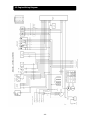
15. Engine Wiring Diagram ............................................................. 40
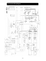
16. Generator Wiring Diagram ........................................................ 41

- 2 -
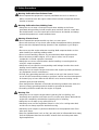
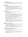
Warning: Suffocation from Exhaust Fume
• Do not operate the equipment in a poorly-ventilated area such as indoors or
within a tunnel because the engine exhaust fume includes components that are
harmful to humans.
Warning: Suffocation from Welding Fume
• Always be sure to wear a fume-proof mask when welding as the fumes
generated during welding include harmful gases and dust. Also be careful that
the wind direction is not such that it will cause fumes to be inhaled and always
operate the equipment in a well-ventilated area.
Warning: Electric Shock
• Do not operate the equipment with any doors or covers open.
• Do not touch wirings or any electric parts inside the equipment during operation.
• Do not touch the equipment during operation if the equipment or your body is
wet.
• Be sure to stop the engine whenever touching Weld output terminals such as
when installing or removing welding cables.
• Do not connect welding cables to any part other than Weld output terminals.
• Do not insert any metallic objects, such as pins or wires, into AC output
receptacles or remote control
l
er connectors.
• Always be sure to turn off all breakers before installing or removing devices
using AC output receptacles.
• Always be sure to repair the corresponding earth leakage location when earth
leakage circuit breakers operate.
• Always be sure to stop the engine and remove the engine key before performing
any equipment check or maintenance.
• Ground every grounding terminal to the earth as set out in the manual. If even
one of all is disconnected by mistake or accident, it will be much more dangerous
for human injury or burns than the NO RELAY case, because leaking current
inevitably goes through the body.
• Even though all the terminals of the loads have been grounded to the earth, the
bonnet (canopy) grounding terminal should be grounded to the earth.
• Grounding should be made after the engine is stopped.
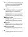
Warning: Fire
• Always be sure to stop the engine when inspecting fuel or refueling, and
absolutely never perform such tasks near fire or other open flame. Wait until the
engine has completely cooled before inspecting fuel or refueling.
• Always be sure to wipe up any spilled fuel or oil.
• Absolutely never use the equipment if there is a fuel, oil or cooling water leak,
and be sure to always repair the leak before using.
• Absolutely never inspect or perform maintenance to the equipment near fire or
other open flame.
• Keep any ignitable items (such as fuel, gas and paint) or inflammable items away
from the equipment because the muffler, exhaust fume and other parts attain
high temperatures.
1. Safety Precautions

- 3 -
Warning: Fire
• Keep any ignitable items (such as fuel, gas and paint) or inflammable items away
from the work area due to the scattering of weld spatter that occurs during
welding.
• Provide at least 1 meter (3 feet) of distance between the equipment and walls
and other obstacles, and operate the equipment on a flat surface.
• Allow the equipment to cool before covering with protective covers and similar
items.
• Do not ground wiring of earth leakage relay of the equipment to piping that
passes through flammable material.
Warning: Injury
• Do not operate the equipment with any doors or covers open. There is a danger
of hair, body parts and other items being caught up in moving parts such as
cooling fans and belts.
• Do not modify the equipment and do not operate with parts removed.
• Always be sure to stop the engine and remove the engine key before performing
any equipment check or maintenance.
• The lifting lug is designed to be used only for lifting the equipment. Do not lift the
equipment with any heavy items (such as a trailer, gas canister and additional
fuel tank) added to the equipment.
• When lifting the equipment, always use a lifting lug. Do not lift the roping lug, for
it may cause equipment to drop due to roping lug breaking off.
Warning: Injury to Eyes and Skin
• Use protective gear, such as rubber gloves, when inspecting or replacing the
battery due to the dilute sulfuric acid in the battery fluid. Be sure that fluid does
not get into eyes, or on skin or clothing.
• If battery fluid gets into the eyes, or on the skin or clothing, immediately wash
with a large amount of water, and always be especially sure to seek medical
attention if it gets into the eyes.
Warning: Explosion
• Do not operate the equipment or recharge the battery when the battery fluid level
is below the lower level.
• Do not generate any sparks near the battery and do not allow any fire or other
open flame near the equipment because the battery generates ignitable gas.
Warning: Electromagnetic Interference
• Persons using a heart pacemaker are not allowed near the welder or welding
work area while welding is being performed without the permission of a doctor.
The welder generates a magnetic field while energized that can negatively affect
pacemaker operation.
Caution: Suffocation from Exhaust Fume
• Do not direct the engine exhaust towards passersby, private homes or similar
persons/locations because the engine exhaust fume includes components that
are harmful to humans.

- 4 -
Caution: Electric Shock
• Do not sprinkle water on the equipment and do not use where exposed to rain.
• If wearing gloves, be sure to always wear gloves with dry insulation properties.
Do not wear gloves that are damaged or wet.
Caution: Burn
• The engine, muffler and similar parts are extremely hot during operation and
immediately after stopping the equipment. Never touch hot parts.
• Never open the radiator cap during operation or immediately after stopping the
equipment. Hot cooling water and steam will spurt out.
• Always be sure to stop the engine and allow it to cool before inspecting or
changing the engine oil. Opening the oil gauge or oil plug during operation will
result in hot oil spurting out.
Caution: Injury
• Use this equipment with it situated on a stable level surface so that it is
prevented from moving.
• Do not move the equipment during operation.
• Always be sure to turn off the switches of all devices using the equipment and
turn off the equipment breakers before starting the engine.
• Always be sure to turn off the power switches of all devices using the equipment
when turning on the equipment breakers. Leaving on the power switch of a
device using the equipment when the equipment breakers are turned on could
result in the sudden operation of the corresponding device.
• Do not leave on the power switch of a device using the equipment and do not
connect a device to an AC output receptacles.
• Always be sure to use the lifting lug when lifting the equipment, and lift slowly
and directly straight above.
• Wear a helmet, safety shoes, gloves and similar protective gear when performing
lifting work. Do not stand or get under the equipment while it is suspended.
• Securely fix the equipment with rope or similar item so that it cannot move when
transporting by truck or other vehicle.
Caution: Injury to Eyes and Skin
• Always be sure to wear arc-proof glasses, clothes that completely cover the skin
and other protective gear when welding to protect the eyes and skin from
harmful light rays generated during welding.
• Always be sure to wear leather gloves, apron, shoe covers, arc-proof glasses
(face shield), safety shoes, hard hat and long-sleeve clothing to protect against
the scattering of weld spatter that occurs during welding.
Caution: Physical and Secondary Damage
• Do not use the equipment for any improper applications. Improper usage can
result in an accident or malfunction.
• Do not connect the AC power source to indoor wiring.
• If using the equipment as a power source for medical equipment, you must
check with the medical equipment manufacturer, doctor and hospital before
using the equipment.
• Set the frequency in accordance with the devices using the equipment.

- 5 -
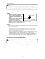
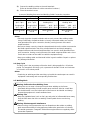
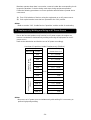
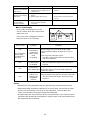
■Locations of Warning Labels
Replace warning labels when they become difficult to see or damaged by affixing
new labels in the specified locations. Order the necessary labels by numbers in
parentheses.
(1) Suffocation from Exhaust Fume (No. X505-007590)
(2) Suffocation from Welding Fume (No. X505-007600)
(3) Electric Shock (No. X505-007610)
(4) Fire (No. X505-007650)
(5) Injury (No. X505-007630)
(6) Injury (No. X505-007690)
(7) Injury (No. X505-007550)
(8) Burn (No. X505-007640)
(9) Burn (No. X505-007620)
(10) Burns (No. X505-007660)
(1) (2)
(3)
(5)
(6)
(7)
(4)
(8)
(9)
(10)
(5)
(6)

- 6 -
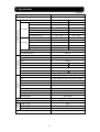
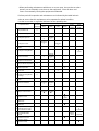
(50/60Hz)
Model DGW500DM-S1
Generating Method Rotating Field
Welding Generator
Operation Single Dual
CC MODE
Rated Current (A) 480 230
Rated Voltage (V) 39.2 29.2
Duty Cycle (%) 60 80
Current Adj. Range (A) 60 – 500 / 65 – 500 30 – 280 / 35 – 280
Welding Rod (mm)
φ2.6 – φ8.0 φ2.0 – φ6.0
Gouging Rod (mm)
φ3.2 – φ9.5 φ3.2 – φ5.0
CV MODE
Rated Current (A) 480 230
Rated Voltage (V) 39.0 22.5
Duty Cycle (%) 60 80
Voltage Adj. Range (V) 14 – 40 14 – 29
Welding Wire (mm)
φ0.6 – φ2.4 φ0.6 – φ2.0
Rated Speed (min
-1
) 3000 / 3600
No Load Voltage (V) MAX 85
AC Generator
Rated Frequency (Hz) 50 / 60
Rated Speed (min
-1
) 3000 / 3600
Phase 1-Phase
Rated Voltage (V) 110 / 115 220 / 230
Rated Current (A) 15A×2 15A×2
Power Factor 1.0
Rated Output (kVA) 3.3 / 3.5 6.6 / 6.9
Rating Continuous
Engine
Model Kubota V1505
Type Vertical, Water-Cooled 4-Cycle Diesel Engine
Displacement (L) 1.498
Rated Output (kW/min
-1
) 24.5 / 3000 29.0 / 3600
Fuel ASTM No.2 Diesel Fuel or Equivalent
Lubricant Oil API Class CD or better
Lubrication Oil Volume (L) 6.0 (Effective 2.0)
Cooling Water Volume (L) 5.6 (Sub Tank Capacity 0.8 L included)
Starting Method Starter Motor
Battery 75D31R(Japanese Industrial Standard)
Fuel Tank Capacity (L) 63
Dimen-
sion
Length (mm) 1680
Width (mm) 700
Height (mm) 950
Dry Weight (kg) 613
2. Specifications

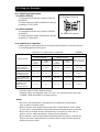
- 7 -
• Shielded Metal Arc Welding
• Semi-automatic Arc Welding (MIG, MAG, Self-Shielded)
• Scratch Start TIG
• Gouging
• Power Source for Light, Electric Tools and Appliances
Caution: Physical and Secondary Damage
• Do not use the equipment for any applications not listed above. Improper usage
can result in an accident or malfunction.
• If using the equipment as a power source for medical equipment, you must
check with the medical equipment manufacturer, doctor and hospital before
using the equipment.
3. Applications
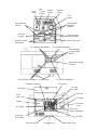
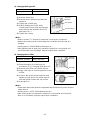
4. Part Names
Weld Terminals A
Weld Terminals B
Operation Panel
Terminal Cover
Single/Dual
Selector
DC Meter
Emergency
Stop Switch
AC Meter
Output
Control
Dial
Arc Control Dial
CV/CC
Selector
Switch
Rod
Selector
Switch

- 8 -
Hour
Meter
Fuel
Meter
Circuit Protector
for Wire Feeder
Idle
Control
Switch
Starter
Switch
Monitor
Lamp
Wire Feeder
Voltmeter
Selector
Forklift Skid
1-P 220/230V Receptacle
Earth Leakage
Circuit Breaker
(ELCB)
Bonnet Grounding
Terminal
1-P 110/115V Breaker
14-Pin Connector
Remote Control
Receptacle
Weld Terminal
Switch
42V/115V
Selector
1-P 110/115V Receptacle
1-P 220/230V Breaker
Fuel Lever
(Water Separator)
Frequency Selector
Oil Plug
Oil Inlet
Fuel Inlet
Cover
Fuel Drain Plug
Oil Drain Plug
Water Drain Plug
Oil Filter
Fuel Inlet
Side Door
Air Cleaner
Battery
Fuse
(60A, 20A)
Fuel Lever
(Fuel Filter)
Sub Tank
Oil Gauge

- 9 -
Accessories
Owner’s and
Operator’s
Manual
Tool
Kit
Lifting Lug
Muffler
(Tail Pipe)
Roping Lug
Top Plate
Door Key
2 Set
Tail Pipe
1 part
Pipe Band
1 part
Engine Key
1 Set

- 10 -
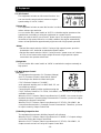
5-1. Idle Control
The equipment includes an idle control function. You
can use the idle control switch to select an engine
speed setting of "AUTO","HIGH".
(1) Auto Idle
The equipment includes an auto idle function in order to reduce noise, save fuel, and
reduce exhaust gas emission.
You can set the idle control switch to "AUTO" so that the engine operates at low
speed when not welding or using the equipment as a power source.
When you start to weld or use as an AC power source, the engine automatically
increases to high speed. When in a no-load condition, the engine automatically
returns to low speed after approximately eight seconds of high-speed operation.
<Note>
• Set the idle control switch to "HIGH" if using a high capacity motor, precision
instruments or AC load with an attached magnetic switch.
• Set the idle control switch to "HIGH" if using as an AC power source of a device
of 0.5 A or less because the engine might not reach a high speed as speed
control does not operate at that level.
(2) High Idle
You can set the idle control switch to "HIGH" to maintain the engine constantly at
high speed.
5-2. Weld Output Control
(1) CV/CC
The equipment incorporates CV (Constant Voltage)
and CC (Constant Current) characteristic feature.
Connecting a wire feeder and then turning the
CC/CV Selector Switch to "CV-WIRE",
semi-automatic welding such as MIG, MAG, SS, etc.
is available to perform.
Connecting the welding cables and then turning the
CV/CC Selector Switch to "CC-STICK, GOUGING", stick welding or arc gouging is
available to perform.
When the CV/CC Selector Switch is positioned at "CV-WIRE", the current from the
terminals becomes Constant Voltage Characteristic. Therefore, you have to adjust
voltage by the Output Control Dial.
When the CV/CC Selector Switch is positioned at "CC-STICK, GOUGING", the
current from the terminals is Constant Current Characteristic. Therefore, you have
to adjust current by Output Control Dial.
(2) Welding Output Pre-Set
The equipment incorporates Welding Output Pre-Set feature.
When the CV/CC Selector Switch is positioned at "CV-WIRE", CV Output voltage
can be Pre-Set by the Output Control Dial
When the CV/CC Selector Switch is positioned at "CC-STICK, GOUGING", CC
Output current can be Pre-Set by the Output Control Dial.
5. Equipment
Output Control Dial
Arc Control Dial
Idle Control Switch

- 11 -
Weaker
Stronger
Arc Control Dial
<Note>
•
The applicable remote controller with 2-Pin plug has an Output control dial which
can be adjusted the output current in the remote area prior to the dial on the
machine.
(3) Arc Control (For CC mode)
The equipment includes an arc control function that
adjusts the arc strength.
You can adjust the setting of the arc control dial of the
short-circuit current of the weld output.
<Note>
•
The arc control function is only for "CC-STICK, GOUGING" mode. It does not
function if using "CV-WIRE".
•
Always turn the arc control dial to "0"(zero) when the scratch start TIG welding is
functioned otherwise a welding current becomes unstable as the arc control is
functioned.
5-3. Remote Control (Option)
You can connect the remote controller to the remote control receptacles to enable
remote operation of weld output adjustment.
<Note>
•
The output control dial on the remote controller connection side of the equipment
does not function when a remote controller is connected.
•
If the remote controller is disconnected from the remote control connector while
welding, the equipment output control dial becomes functional, possibly resulting
in an increase or decrease in weld current.
•
Do not connect the remote controller plug to the receptacle of an extension cord
(cord reel) that is connected to AC power source. Improper connection causes
the caution lamp of the remote controller to light up indicating a fault.
•
Do not connect the receptacle of an extension cord (cord reel) used for the
remote control to any other device besides the remote controller.
•
Set the breaker to "ON" if the cord reel is equipped with one.
Connect directly or use
an extension cord.
Remote Control Receptacle
Remote Controller
Caution
Lamp

- 12 -
DC Meter
AC Meter
Output Control
Dial
Single/Dual
Selector
5-4. Meter
The equipment includes a DC meter that provides digital display of both weld
current and voltage, and an AC meter that provides digital display of voltage and
frequency of single phase 110V generated output.
(1) DC Ammeter – Voltmeter
The DC ammeter and voltmeter display the weld output for both outputs A and B
separately.
If the single/dual selector is set to "SINGLE", the DC meter for output B does not
display current or voltage.
<Note>
•
If the weld mode selector is set to "CV-WIRE", the set voltage that has been
pre-set using the output control dial is displayed by the voltmeter when not
welding. (The DC ammeter display is blank when not welding.)
•
If the weld mode selector is set to "CC-STICK, GOUGING", the set current that
has been pre-set using the output control dial is displayed by the DC ammeter
when not welding. (The voltmeter display is blank when not welding.)
•
During welding, both the DC ammeter and voltmeter display the actual output
values. When welding is completed, both meters display the actual output values
for approximately 8 seconds, after which display returns to the pre-set values.
(2) AC Meter
The AC meter displays the single phase 110V generated output and frequency.
<Note>
•
During operation, the AC meter displays constantly the single phase 110V output
voltage of the AC power source regardless of whether the breaker is set to "ON"
or "OFF".
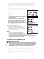
5-5. Error Code Display
The equipment includes an error code
display function that notifies the operator of
any errors during operation. If an error is
detected during operation, error codes are
displayed by the DC and AC meters. If this
occurs, stop operation immediately, and
inspect and repair the location where the
error has occurred.
(Refer to section "14.Troubleshooting".)
Error Code Display
(Also used as DC and AC meters)

- 13 -
5-6. Monitor Lamp
Warning: Injury/Electric Shock
• Do not operate the equipment with any doors or covers open. There is a danger
of hair, body parts and other items being caught up in moving parts such as
cooling fans and belts.
Caution: Burn
• The engine, muffler and similar parts are extremely hot during operation and
immediately after stopping the equipment. Never touch hot parts.
• Never open the radiator cap during operation or immediately after stopping the
equipment. Hot cooling water and steam will spurt out.
• Always be sure to stop the engine and allow it to cool before inspecting or
changing the engine oil. Opening the oil gauge or oil plug during operation will
result in hot oil spurting out.
The equipment includes monitor lamps for "WATER
TEMP", "CHARGE", "OIL PRESS" and "OVERHEAT".
If the equipment is normal, the "CHARGE" and "OIL
PRESS" monitor lamps light up when the starter
switch is switched from "STOP" to "RUN", and all
monitor lamps turn off when the engine is started. If
any error besides that of overheating occurs during
operation, the corresponding monitor lamp lights up
and the engine is automatically stopped.
If the engine is automatically stopped, return the starter switch to "STOP" and
restart the engine. Watch the lit/unlit status of the monitor lamps the next time an
automatic stop occurs and check the error contents.
(1) Water Temperature Monitor Lamp
The water temperature monitor lamp ("WATER TEMP") lights up and the engine is
automatically stopped if the cooling water temperature becomes irregularly high
during operation. If this occurs, inspect the water level of the sub tank and add
cooling water if the water level is insufficient. (Refer to section "7-2. Cooling Water
Inspection".)
If the cooling water in the sub tank is at the specified level, it is probable that
overloading is the cause. Use within the rated output.
(2) Battery Charge Monitor Lamp
The battery charge monitor lamp ("CHARGE") lights up and the engine is
automatically stopped if battery charge fails during operation. If this occurs, it is
probable that there is fan belt damage or a wiring fault. Request repair at the retail
outlet where the equipment was purchased.
(3) Oil Pressure Monitor Lamp
The oil pressure monitor lamp ("OIL PRESS") lights up and the engine is
automatically stopped if the engine oil pressure drops during operation. If this
occurs, inspect the engine oil level and fill with engine oil until it reaches the
maximum level.
Oil Press
Charge
Water Temp
Overheat

- 14 -
<Note>
•
The oil pressure monitor cannot detect oil deterioration. Change the engine oil
periodically. (Refer to section "12. (1) Changing the Engine Oil".)
•
The charge monitor cannot detect battery deterioration or insufficient battery fluid.
Inspect the battery fluid level periodically. (Refer to section "7-5. Battery
Inspection".)
•
Inspect the fuses if the engine is automatically stopped and none of the monitor
lamps ("WATER TEMP", "CHARGE" and "OIL PRESS") light up. (Refer to
section "4. Part Names" for fuse location.)
If a fuse has blown, it is probable that there is a fault in an electric part or the
wiring. Request repair at the retail outlet where the equipment was purchased.
(4) Overheat Monitor Lamp
The overheating monitor lamp ("OVERHEAT") flash and the equipment cuts the
output if the equipment is used excessively over the duty cycle or output. Then it is
probable that overloading is the cause. Use within the rated duty cycle or output.
(Refer to section "14.Troubleshooting" for Error Code Display.)
<Note>
•
There may be a case that the lamp will not flash, depending on the weather
condition.
5-7.
..
.Frequency Selector
Warning: Injury/Electric Shock
• Do not operate the equipment with any doors or covers open. There is a danger
of hair, body parts and other items being caught up in moving parts such as
cooling fans and belts.
Caution: Burn
• The engine, muffler and similar parts are extremely hot during operation and
immediately after stopping the equipment. Never touch hot parts.
Caution: Physical and Secondary Damage
• Set the frequency in accordance with the devices using the equipment.
This equipment can operate at either
50Hz or 60Hz.
Set the frequency selector located
inside the side door to change the
frequency in accordance with the
devices using the equipment.
5-8. Earth Leakage Circuit Breaker and Grounding
Warning: Electric Shock
• Always be sure to repair the corresponding earth leakage location when earth
leakage circuit breakers operate.
Warning: Fire
• Do not ground wiring of earth leakage circuit breakers of the equipment to piping
that passes through flammable material.
Frequency
Selector

- 15 -
The equipment includes earth leakage circuit breakers (solidly grounded type) in
order to prevent electric shock. Immediately isolate the electrical circuit if earth
leakage occurs due to insulation failure in devices using the equipment or similar
reason.
(1) Operation Check of Earth Leakage Circuit Breaker
Be sure to always check the earth leakage circuit breakers before starting operation
according to the following procedures.
1) Start the engine.
(Refer to section "8-1. Starting the Engine".)
2) Set the idle control switch to "HIGH".
3) Set the ELCB lever to "ON".
4) Press the ELCB test button.
Operation is normal if the ELCB lever lowers and
turns off at this time.
5) Push up the ELCB lever to the "ON" position.
There is a fault in the earth leakage circuit breakers
if operation cannot be checked according to the
above procedures. Request repair at the retail outlet
where the equipment was purchased.
(2) Bonnet Grounding Terminal
The equipment includes a bonnet grounding
terminal in order to connect bonnet ground wire.
A neutral point of the AC power source is connected
to the bonnet grounding terminal.
<Note>
•
Connect using a plug with a grounding pole.
•
If using a plug without a grounding pole, perform
grounding work and check that used devices are connected to ground.
•
Securely ground the bonnet grounding terminal to the metal frame of the vehicle
if transporting the equipment by truck or trailer.
(3) If an Earth Leakage Circuit Breakers Operates
Caution: Electric Shock/Injury
• Always be sure to turn off the power switches of all devices using the equipment
when turning on the equipment breakers after an earth leakage circuit breakers
operates. Leaving on the power switch of a device using the equipment when the
equipment breaker is turned on could result in the sudden operation of the
corresponding device.
The ELCB lever moves to "OFF" when earth leakage circuit breakers operate.
When this occurs, immediately stop the engine and repair the earth leakage
location.
After repairing all faults, push up the ELCB lever to the "ON" side to reset the
system.
Test Button
ELCB
Bonnet Grounding
Terminal
Idle Control Switch

- 16 -
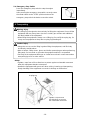
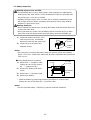
6. Transporting
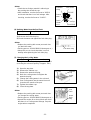
5-9. Emergency Stop Switch
Press the emergency stop switch to stop the engine
immediately.
After pressing the emergency stop switch, securely return
the starter switch to the "STOP" position and turn the
emergency stop switch clockwise to reset the switch.
Warning: Injury
• The lifting lug is designed to be used only for lifting the equipment. Do not lift the
equipment with any heavy items (such as a trailer, gas canister and additional
fuel tank) added to the equipment.
• When lifting the equipment, always use a lifting lug. Do not lift the roping lug, for
it may cause equipment to drop due to roping lug breaking off.
Caution: Injury
• Always be sure to use the lifting lug when lifting the equipment, and lift slowly
and directly straight above.
• Wear a helmet, safety shoes, gloves and similar protective gear when performing
lifting work. Do not stand or get under the equipment while it is suspended.
• Securely fix the equipment with rope or similar item so that it cannot move when
transporting by truck or other vehicle.
<Note>
•
Tighten a rope from all four-directions to protect against unintended movement
when this equipment intends to transport.
•
Handle the equipment with great care when raising, lowering and transporting.
Rough handling of the equipment can result in damage or malfunction.
Stop
Reset
Roping Lug
Tighten a rope from all
four-directions to prevent
the unintended movement.

- 17 -
7. Pre-Operation Inspection
Warning: Injury/Electric Shock
• Do not operate the equipment with any doors or covers open. There is a danger
of hair, body parts and other items being caught up in moving parts such as
cooling fans and belts.
• Always be sure to stop the engine and remove the engine key before performing
any equipment check or maintenance.
Warning: Fire
• Always be sure to wipe up any spilled fuel or oil.
• Absolutely never use the equipment if there is a fuel, oil or cooling water leak,
and be sure to always repair the leak before using.
• Absolutely never inspect or perform maintenance to the equipment near fire or
other open flame.
Caution: Burn
• The engine, muffler and similar parts are extremely hot during operation and
immediately after stopping the equipment. Never touch hot parts.
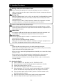
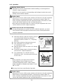
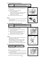
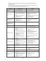
7-1. Engine Oil Inspection
Caution: Burn
• Always be sure to stop the engine and allow it to cool before inspecting or
changing the engine oil. Opening the oil gauge or oil plug during operation will
result in hot oil spurting out.
Situate the equipment on a level surface
and completely insert the oil gauge to
inspect the oil level.
Inspect the oil level before starting
operation and, if it has decreased, fill with
oil until it reaches the maximum level.
<Note>
• The oil level cannot be accurately
checked if the equipment is at an angle.
• Operating the equipment when the oil
has been filled above the maximum level
can result in engine cylinder internal
damage.
Oil Gauge
Oil Plug
Oil Inlet
Oil
G
auge
MAX
MIN
OK
Not
Enough
Too
Much
Page is loading ...
Page is loading ...
Page is loading ...
Page is loading ...
Page is loading ...
Page is loading ...
Page is loading ...
Page is loading ...
Page is loading ...
Page is loading ...
Page is loading ...
Page is loading ...
Page is loading ...
Page is loading ...
Page is loading ...
Page is loading ...
Page is loading ...
Page is loading ...
Page is loading ...
Page is loading ...
Page is loading ...
Page is loading ...
Page is loading ...
Page is loading ...
Page is loading ...
Page is loading ...
Page is loading ...
Page is loading ...
-
 1
1
-
 2
2
-
 3
3
-
 4
4
-
 5
5
-
 6
6
-
 7
7
-
 8
8
-
 9
9
-
 10
10
-
 11
11
-
 12
12
-
 13
13
-
 14
14
-
 15
15
-
 16
16
-
 17
17
-
 18
18
-
 19
19
-
 20
20
-
 21
21
-
 22
22
-
 23
23
-
 24
24
-
 25
25
-
 26
26
-
 27
27
-
 28
28
-
 29
29
-
 30
30
-
 31
31
-
 32
32
-
 33
33
-
 34
34
-
 35
35
-
 36
36
-
 37
37
-
 38
38
-
 39
39
-
 40
40
-
 41
41
-
 42
42
-
 43
43
-
 44
44
-
 45
45
-
 46
46
-
 47
47
-
 48
48


Shindaiwa DGW500DM-S1 User manual
- Category
- Welding System
- Type
- User manual
Ask a question and I''ll find the answer in the document
Finding information in a document is now easier with AI
Related papers
-
Shindaiwa DGW500DM-200 User manual
-
-
-
-
-
-
-
-
-
Other documents
-
 Mosa TS 200 DES/EL Owner's manual
-
Lincoln Electric VANTAGE 575 Operating instructions
-
-
Lincoln Electric VANTAGE 500 Operating instructions
-
Lincoln Electric Vantage 400 Operating instructions
-
Miller MF470056E Owner's manual
-
-
-
-
Lincoln Electric Vantage 300 Operating instructions
