Page is loading ...

Model N-063
SAQ8705
Thank you for purchasing a Noritz Gas Water Heater. Before using this water heater, please:
•Read this manual to learn how to operate this water heater correctly.
•Make sure the date and location of purchase indicated on the warranty registration card is
included separately.
•Keep this manual (and the warranty registration card) where it can easily be found whenever
necessary. NORITZ America Corporation
WARNING: If the information in this manual is not followed exactly, a fire or
explosion may result causing property damage, personal injury or death.
-Do not store or use gasoline or other flammable vapors and liquids in the
vicinity of this or any other appliance.
-WHAT TO DO IF YOU SMELL GAS
••
••
•Do not try to light any appliance.
••
••
•Do not touch any electrical switch; do not use any phone in your building.
••
••
•Immediately call your gas supplier from a neighbor’s phone. Follow the
gas supplier’s instructions.
••
••
•If you cannot reach your gas supplier, call the fire department.
-Installation and service must be performed by a qualified installer, service
agency or the gas supplier.
*SAQ8705 T*
R
“Owner’s Manual and Installation Guide
and Warranty Registration Card”

2 3
Prohibited Don’t
touch.
Don’t
disassemble
the equipment.
Don’t touch
with a wet
hand.
No flame.
High
Temperature.
To prevent damage to property and injury to the user, the icons shown below will be used to warn of
varying levels of danger.
Every indication is critical to the safe operation of the water heater and must be understood and
observed.
Potential dangers from accidents during installation and use are divided into the following three
categories. Closely observe these warnings, they are critical to your safety.
Other icons
Danger
Warning
Caution
Ignoring this indication may cause immediate danger of death or
serious injury.
Ignoring this indication may result in death or serious injury.
Ignoring this indication may result in serious injury or physical
damage.
The content following this icon is necessary to understand for safe
and easy use of this water heater.
Remark
Be sure
to do. Ground.
Electric
Shock.
Danger
Do not use the water heater when
the exhaust pipe is displaced, has
holes, or is corroded.
This may allow exhaust to leak from the
pipe, which can result in death from
carbon monoxide poisoning.
If you detect a gas leak:
1. Do not try to light any appliance
2. Do not touch any electrical
switch; do not use any phone in
your building.
3. Immediately call your gas
supplier from a neighbor’s phone.
Follow the gas supplier’s
instructions.
4. If you cannot reach your gas
supplier, call the fire department.
A flame or spark may
ignite the leaked gas.
Indications depending on the level of damage or injury
Contents
Contents ........................................................................................................ 2
Owner’s Manual
IMPORTANT SAFETY INFORMATION......................................................... 3
Names and Functions of Components ....................................................... 8
Operation (Remote controller)..................................................................... 9
Initial Operation ........................................................................................... 11
Running /Adjusting Hot Water.................................................................... 12
Tub Level Alarm........................................................................................... 14
Muting the Sound of the Remote Controller ............................................. 16
Prevention of Damage Caused By Freezing in Cold Temperatures ....... 17
Regular Maintenance................................................................................... 19
Troubleshooting .......................................................................................... 21
Follow-up Service ........................................................................................ 25
Specifications .............................................................................................. 26
External outfitting ........................................................................................ 27
Combustion unit and gas route.................................................................. 29
Hot-water feed route 1................................................................................. 31
Electronic control unit................................................................................. 35
Electronic controller, remote controller and attached set....................... 36
Installation Guide......................................................................................... 37
1. Included accessories ............................................................................ 38
2. Before installation ................................................................................. 38
3. Choosing installation site..................................................................... 39
4. Installation clearances .......................................................................... 40
5. Installation.............................................................................................. 42
6. Exhaust piping installation ...................................................................43
7. Gas piping ..............................................................................................45
8. Supply water and hot water piping ......................................................46
9. Electric wiring ........................................................................................47
10. Trial operation........................................................................................ 50
Dimensional outline drawing...................................................................... 51
Remote Controller
Installation Guide......................................................................................... 52
IMPORTANT SAFETY INFORMATION -1
(Be sure to read and observe all safety information in this manual.)

4 5
If you detect abnormal combustion
or abnormal odors, or during an
earthquake, tornado or fire:
1. Turn off the hot water supply
2. Turn off the power to the water
heater
3. Turn off gas and water at the
main
4. Consult the nearest Noritz agent
This will prevent fire, electric shock or
damage to the unit.
Check the temperature of the
running hot water by hand before
taking a shower.
Also check the temperature by
hand before stepping into the bath
tub.
Do not turn off the water heater or
change the water temperature while
someone is bathing.
This can result in scalding or temperature
shock.
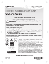
Leave the proper clearance between
the water heater and nearby objects
(trees, timber, boxes with flammable
materials etc.).
Do not place or use a spray can
near the heater or the exhaust vent
terminal.
This may result in an explosion or fire.
*Indicates suggested clearances for
maintenance.
Left side:
Min. 2" Right side:
Min. 2"
Min. 3" from
exhaust pipe
Front:
Min. 24"*
Do not place combustibles such as
laundry, newspapers, oils etc. near
the heater or the exhaust vent
terminal.
These may cause a fire.
Do not use combustible chemicals
such as oil, gasoline, benzene etc.
in the vicinity of the heater or the
exhaust vent terminal.
These may cause a fire.
Check the air supply vent for dust
or obstructions.
Exhaust vent
terminal
Be sure the gas supplied matches
the gas on the rating plate.
Using an improper gas or electric supply
may cause improper operation, fire or
electric shock.
Do not allow small children to play
unsupervised in the bathroom.
Do not allow small children to
bathe unsupervised.
Accidents may occur.
Consult the nearest Noritz agent if
the water heater location needs to
be changed.
Contact a qualified service
technician for any necessary
repairs, service or maintenance.
Warning Warning
IMPORTANT SAFETY INFORMATION -2
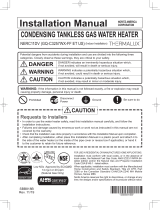
Manufacturing year and month
XXXX. XX-XXXXXX
Top of heater
SERIAL NUMBER
Back of heater
Front of heater
Side of heater
Minimum Clearances from Combustible of Non-combustible Construction
Clearance
Made in JAPAN XXXX XXXXXX
Type of Gas : Natural Gas
Max. Water Pressure : Min. 15psi ~ Max. 150 psi
Electrical Rating : AC 120 Volts 60 Hz
Manifold Gas Pressure : Min. 0.63 ~ Max. 2.3 inches
Inlet Gas Pressure : Min. 3.5 ~ Max. 10.5 inches
Recovery Rate : 241 Gallons/Hour
BTU Input : Max. 179,000 ~ Min. 22,000
Model : N-063
Tel : (949)420-0409
20492 Crescent Bay Dr.Ste.104.Lake Forest CA 92630
NORITZ AMERICA CORPORATION
Automatic Instantaneous Water Heater
REQUIRED CLEARANCES TO COMBUSTIBLES
ANSI Z21.10.3 2000
FOR YOUR SAFETY
Do not store or use gasoline or other flammable vapors and
liquids in the vicinity of this or any other appliances
Outdoor Install Indoor Install
36 inches
1 inch
24 inches
6 inches 2 inches
4 inches
1 inch
12 inches

6 7
Do not disassemble the remote controller.
This may cause damage to the heater or
unexpected accidents.
Do not use benzene, oil or fat detergents
to clean the remote controller.
This may cause deformation.
Do not get the remote controller wet.
Although it is waterproof, too much water can
cause damage.
Do not splash water on the remote
controller. Do not expose the remote
controller to steam.
Do not locate the remote controller near stoves or
ovens, this may cause damage or failure.
Take measures to prevent the unit from
freezing. ( p.17)
If water is allowed to freeze inside the unit, the unit
may be damaged, and water can leak out of it.
Take necessary measures to prevent
freezing of water and leakage of gas when
leaving the unit unused for long periods of
time. ( p.18)
If it is snowing, check the air inlet, exhaust
gas vent and exhaust vent terminal for
blockage.
This can result in improper function or damage to
the unit.
Do not use parts other than those specified
for this equipment.
Do not drink water that was inside the unit
for an extended period of time, do not
drink the water that comes out of the unit
just after the first use of hot water in the
morning.
Use it for other purposes.
Clean the filter on the water inlet.
If you don’t know where the filter is, contact the
nearest Noritz agent.
Keep the area around the unit clean.
If boxes, weeds, cobwebs, cockroaches etc. are
allowed to be in the vicinity of the unit, damage or
fire can result.
Do not install the equipment where the
exhaust will blow on walls or windows.
This may cause damage or discoloration.
Do not use spring water or well water.
This can cause damage and reduce durability.
Check for proper combustion during
operation and that the flame stops after
operation is finished.
To prevent accidents due to gas.
Be sure to electrically ground the
unit.
Do not touch the power cord with
wet hands.
Keep power cord free of dust.
This can cause a fire.
Do not use a broken or modified
power cord. Do not bind, bend or
stretch power cords.
Do not place things on them,
scratch. Do not scratch, modify or
subject them to impact or force.
Do not use the water heater for
other than hot water supply,
shower and bath.
To prevent unexpected accidents.
Do not touch the exhaust vent pipe
during or immediately after
operation of the water heater.
Do not connect the water heater to
a solar water heater.
This can result in unreliable temperature
control, scalding or equipment failure.
Do not use hair spray or spray
detergent in the vicinity of the
heater.
These may cause damage to the heater.
Caution Remark
IMPORTANT SAFETY INFORMATION -3

8 9
Operation (Remote Controller)
Main remote controller (RC-7646M)
Display
( next page) For setting the hot
water temperature,
and other adjustments.
Operation button
For turning the
heater on and off.
Water fill set button
For setting the level of
hot water.
(p.14 and 15)
Setting button
* Before use, remove the protective sheet from the remote controller surface.
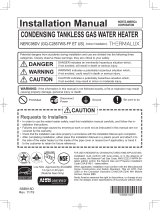
Name and Functions of Components
Indoor wall mounted power vented model
* The above illustration shows an example of installation.
The shape of the piping, and the location of the water main, gas main and power cord will
depend on the specific installation.
Main unit
Exhaust gas vent
Front cover
Air inlet
Water supply valve
Gas valve
Water filter
Mounted inside.
(p.20)

10 11
Initial Operation
Before the first use of your water heater, the following preparations and checks are necessary.
1Fully open the water supply
valve. (Turn the handle so
that is lines up with the pipe.)
Open a hot water fixture to confirm that
water is available, and then close the
fixture again.
3Fully open the gas valve.
Hot water fixture
Follow steps 1 through 4.
2
Water temperature
(Ex.: 104°F)
Water level
The display will flash.
(p.15)
Failure indicator
When this indicator
lights, the hot water
temperature can be set.
( p.13)
Priority indicator
The illustration below shows the remote controller display. What is actually
displayed depends on how the water heater is set.
Burning indicator
A number will flash if
a failure occurs.
(p.24)
Display
4Turn on the power.
ONOFF

12 13
1Press the
Operation button.
How to use
Running /Adjusting Hot Water
Previously set
temperature
(Ex.: 104°F)
The temperature will be
indicated on the display.
1
2<With Operation button Off>
On
<Remote controller display>
On
Caution
High Temperature
To prevent scalding:
•Check the water temperature by hand before bathing or
showering.
•When you set the temperature to 140°F or 167°F, the
display will flash for 10 seconds to remind you that this
is a high temperature.
•Be careful the next time you use the heater after setting
it at 140°F or 167°F. Check the temperature setting
before using.
•Do not allow anyone to change the water temperature
while hot water is running.
Flash for 10 sec light up
4
3Run hot water.
2
Adjust temperature.
Check the indicator lights.
Hot
Cold
Water temperature
If the remote controller was left set at 167°F the last time it was used, the setting will drop to
140°F as a safety precaution.
On
(°F: )
The figures shown below are just examples. The actual temperature setting
necessary depends on the usage, the length of piping and the season.
Stop the hot
water.
*Initial setting (factory setting at shipment)=104°F
Off
Shower, hot water supply,
etc.
Washing
dishes, etc.
Hot water supply, etc.
High
temperature
99 100 102 104 106 108 109 111 113 115 117 118 140 167
If using a mixing valve, set the water
temperature on the remote control
approximately 18°F higher than
usual.
(
Check the temperature
)
if you will not be
changing it.
Temperature above 125 degree can scald.

14 15
2
Adjust temperature.
1Press the
Operation button.
How to use
Tub Level Alarm
Previously set temperature
(example: 104°F)
Hot
Cold
The temperature will be indicated
on the display.
1. Plug the bath drain.
On
Preparation
3
2,3
1
Check the indicator lights.
Water temperature
On
<With the operation button off>
(
Check the
temperature if you will
not be changing it.
)
5Stop the hot
water when the
alarm sounds.
4Run the hot
water.
3Adjust tub level
setting.
On
•If water is being used besides what is needed for the tub, the alarm will sound before the set
level is reached in the tub.
•If there was water remaining in the tub, or if the water is not manually turned off after the
buzzer sounds, the tub may overflow.
•If there was water remaining in the tub, the temperature after the tub is filled the rest of the
way will be less than the set temperature.
<The setting is remembered>
Water level will be flashing (ex. 45 gal.)
* The level can be adjusted while
the indicator is flashing.
* The temperature will return after
ten seconds.
Set the water level of your tub, the
choices for settings are anything
between 10 and 65 gal., in increments
of 5, and 80, 90, 105 and 990 gal.
(Reference values)
The alarm will sound when
the specified level has been
reached. Stop the water.
The alarm will sound for ten
seconds when the water
reaches the specified level.
(But the water will continue to run
unless it is manually turned off.)
Press the operation button (the level
setting indicator will flash) and then
the setting button. Increase
Decrease
Off
* Initial factory setting at shipment: 104°F
Water temperature
Warmer
99 100 102 104 106 108 109111 113 115 117 118
HotWarm
The temperatures shown below are only examples. Your actual
reaction to set temperatures will depend on the season and the
length of piping.
Note:
The alarm will not sound if it
is set for 990 gal.
Note:
The alarm will not
sound if it is set for 990
gal.

16 17
1. Push the operation button and confirm
that the operation light comes on.
2. Close the gas supply valve.
3. Open a hot water fixture and let it run
for approx. 1 minute, and then check
that the number 11 is flashing on the
remote controller display.
* It is possible that a different number may be displayed
on the remote controller, but as long as it is flashing,
you may continue.
4. Open a hot water fixture, and keep a small amount of hot
water running. (.1 gal./minute or about .2” thick.)
* If there is a mixing valve, set it to the highest level.
5. The flow may become unstable from time to time. Check
the flow 30 minutes later.
When any button on the remote controller is
pushed, a sound is emitted. This sound can be
muted if you desire.
Water level alarm cannot be muted.
1
How to use
Muting the Sound of the Remote Controller
If water will not flow because it is frozen
Prevention of damage caused by freezing in cold temperatures
1. Close the gas and water valves.
2. Turn off the operation button.
3. Open the water supply valve from time to time to check whether water is running.
4. When the water is flowing again, check for water leaks from the equipment and piping, or
follow steps 1 through 4 on p.11 (“Initial Operation”).
The freeze prevention heaters will
not prevent the plumbing external
to the unit from freezing. Protect
this plumbing with insulation or an
electric heater. If you are still
worried that your heater will
freeze, contact the nearest Noritz
agent.
When the temperature drops, the freeze-prevention
heaters are automatically activated to keep the unit
warm and prevent it from freezing.
Normal cold [outside temperatures more than 5°°
°°
°F with no wind]
The heater and piping can be damaged if cold temperatures cause water to freeze inside the
unit. The damage can be prevented with the following method:
At these temperatures, the units have freeze prevention heaters that will prevent freezing.
* Do not disconnect the power. The freeze prevention heaters will not work if the power
is disconnected.
* The freeze prevention will work regardless of whether the operation button on the remote
controller has been turned on.
•If the heater or the piping is frozen, do not use the heater, or it may get damaged.
•Repairs for damage caused by freezing is not covered by the warranty.
For severely cold temperatures []
Run water to prevent freezing.
•This method can be applied
not only to the heater, but also
to the water supply, water
piping and a mixing valve.
•Remember that if the mixing
valve is set to the maximum
level, there is a risk of scalding.
•If freezing still might occur,
drain the water from the unit
following the steps on p.18.
Hot water fixture
.2” thick
outside temperature including wind chill
less than 5°°
°°
°F
Sound
Mute
No sound
1
With the remote controller off, press
and hold the operation button for five
seconds to turn the sound on or off.
After approx.
5 sec.,
sounds.

18 19
Fixture
1Turn on the operation button, and check that the light comes on.
2Close the gas valve.
3Open a hot water fixture, and keep it open for approximately 1 minute until the number 11
is flashing on the remote display.
* It is possible that another number may displayed on the remote controller, but as long as
the number is flashing, you may continue.
4Close the water supply valve.
5Keep the operation switch on and disconnect the power.
6Fully open all hot water fixtures.
7Remove inlet and outlet drain plugs. (0.1 to 0.2 gal. will drain
out of the unit.)
8When the water is completely drained, replace all drain plugs
and close the hot water fixtures.
To turn the unit back on
To avoid burns, wait until the equipment cools down before
draining the water. The appliance remains hot after it is
turned off.
Drain the water as follows:
High Temperature
Provide a pan or bucket for drainage to prevent water damage.
Caution
1. Check that all drain plugs are inserted.
2. Check that all hot water fixtures are closed.
3. Follow the procedure on p.11 “Initial operation”.
This method cannot prevent the water supply, hot water piping and water supply valve from
freezing.
Be sure to protect them with insulation or an electric heater.
(If you are still worried the unit will freeze, consult the nearest Noritz agent.)
7Drain plug
If the water heater will not be used for a long period of time
To avoid burns, wait until the equipment cools down
before draining the water. The appliance remains hot
after it is turned off.
High Temperature
Maintenance (once a month)
Wipe the outside surface with a wet cloth, then dry the surface. Use a neutral detergent to clean
any stains.
•Do not use benzene, oil or fatty detergent to clean the remote controller.
Deformation may occur.
•The remote controller is waterproof, but it should be kept dry as much as possible.
Caution
Regular Maintenance
Inspection (Once a month)
Check
For laundry, newspaper, timber,
oil, spray cans and other
combustible materials. ( p.5)
Equipment
Remote controller
Wipe the surface with a wet cloth.
Check
For abnormal sounds
during operation.
For abnormalities in
external appearance,
change in color or flaws.
Check
For water leaks from the
equipment and piping.
Check
Check
For dust and soot in
the exhaust vent or
exhaust vent terminal.
Do not touch with wet hands.
For dust in the air inlet.
Check

20 21
Maintenance (once a month)
If the water filter is covered with debris, the hot water will not run smoothly, or cold water may
come out. Clean the filter as explained below.
* To avoid burns, wait until the equipment cools down before draining the water. The
appliance remains hot after it is turned off.
Water filter
1. Close the water supply valve.
2. Open all hot water fixtures.
3. Loosen the Drainage Outlet.
4. Remove the Drainage Outlet from the band.
(see illustration on right).
* Water will drain out.
5. Clean the filter with a brush under running
water.
6. Replace and screw the Drainage Outlet
closed.(Take care not to lose the packing.)
7. Close all hot water fixtures.
8. Open the water supply valve and check that
water is not leaking from the Drainage Outlet.
Water supply valve
Temperature
Hot water is not available when
the hot water fixture is opened. •Are the gas and water supply valves fully open?
•Is the water supply cut off?
•Is the hot water fixture sufficiently open?
•Is the heater frozen?
•Is the gas meter working?
•(For LP) Is there enough gas in the tank?
•Is the operation button turned on?
•Have you allowed enough time for the cold water in the
pipes to drain out?
•Are the gas and water supply valves fully open?
•Is the water temperature setting appropriate ( p.12
and p.13)?
•If the supply water is at a high temperature, you may
need to increase the flow rate through the heater to get
a low temperature out of it.
Hot water is not available at low
temperatures.
Cold water comes out when the
fixture is barely opened. Only
cold water is available at low
flow rates.
•The heater stops burning when the flow of hot water
becomes less than 0.75 GPM. Open the hot water
fixture more, and the water temperature will stabilize.
Troubleshooting-1
•Are the gas and water supply valves fully open?
•Is the water temperature setting appropriate ( p.12
and p.13)?
Hot water is not available at
high temperatures.
Band
Packing
Drainage Outlet
Water filter

22 23
Remote controller
The water temperature changes
after a power failure or when the
power is disconnected.
The operation light does
not come on •Has there been a power failure?
•Is the power connected properly?
•The time on the controller may need to be reset after a
power failure or after the power has been disconnected.
Also, the hot water temperature indicator, and tub level
alarm may have been reset.
Amount of hot water
The pressure at a certain
fixture is not constant. •When hot water is demanded at other fixtures, the
amount available may be reduced.
•Pressure fluctuations and other plumbing conditions can
cause the temperature and pressure at a fixture to be
unstable, but it should stabilize after a short time.
•To keep the temperature stable, the heater limits the
amount of water that can flow through it to a small
amount initially, but the amount increases over time.
The display (LCD) is unstable. •The liquid crystal display may become unstable when
the remote controller is cleaned with a dry cloth (Leave it
for 30 minutes and it will return to normal).
Other
The Heater stops burning during
operation. •Are the gas and water supply valves fully open?
•Is the water supply cut off?
•Is the hot water fixture sufficiently open?
•Is the gas meter working?
•(For LP) Is there enough gas in the tank?
•This is normal on cold days.White smoke comes out of the
exhaust vent on a cold day.
The hot water becomes turbid. •This is harmless. Small bubbles appear as the air in the
water is heated and depressurized rapidly to
atmospheric pressure. It is similar to the bubbles in beer
or carbonated beverages.
Water leaks from the drain plugs on
the outlet. •When the main unit is highly pressurized, water will leak
from the drain plugs as a safety so that the unit is not
damaged by the high pressure.
•These plugs are pressure relief valves. If water is
leaking out of them, excessive pressure is being
supplied to the unit.
Sound
The fan can be heard after
operation is stopped. •The fan runs for a while to accelerate ignition after the
operation button is turned on.
Troubleshooting-2

24 25
Burner has been used
continuously for 60
minutes or more.
Turn off the hot watertap, press the power
switch OFF and the press it ON again. If
<01> is not displayed, then operation is
nomal.
Ignition error Check whether the gas valve is open. Turn
off the operation button, open a hot water
fixture, and turn on the operation button
again. If the problem is solved, the flashing
number will disappear.
Indication Cause Action
Flashing
åÃè·ï\é¶Ç Ç®í Ç Ç ÇæÇ Ç¢ åÃè·ï\é¶Ç Ç®í Ç Ç ÇæÇ Ç¢
Check for error code on the remote controller
If there is a problem with the unit, a numerical error code will flash on the remote controller.
If this occurs, take appropriate measures as listed below.
Ex. When an error code appears, the display and the operation light will flash
together.
Contact our sales agent if:
•Any other flashing number appears.
•An error code is indicated again after the above actions were followed.
•You have any other questions.
<Main remote controller>
A warranty registration card is included separately.
Be sure that the shop name, date of purchase and other necessary items are filled in.
Read the content carefully, and keep the warranty card in a safe place.
For repairs after the warranty period, there will be a charge on any service, and service will only
be performed if the unit is deemed repairable.
Follow-up service
Requesting service
Minimum period of time for stocking repair parts
Noritz will stock repair parts for this unit for a minimum of seven years after production has
ceased.
These are the parts necessary to repair or maintain this unit.
Reinstallation
Warranty
First follow the instructions in the troubleshooting section (p.21 to p.24). If the error is not
corrected, contact our sales agent.
If you want to reinstall the appliance at a different location, confirm that the gas and power
supply indicated on the rating plate are available at the new location. If you are not sure,
consult the local utility company.
If you move to a region that uses a different type of gas, conversion and adjustment of the
appliance will be necessary. This work will be charged for even during the warranty period.
* It should be noted that a request for service may be rejected if the water heater is
installed in a location where working on the unit may be dangerous. If so, you will have
to consult a plumber to remove the unit and bring it to a safe location.
We will need to know:
The Model ..............(check the rating plate)
*See p.4 for the location of the label
Date of purchase ... (see the warranty)
Details of error ...... (flashing error codes)
Your name, address, and telephone number
Desired date of visit
Troubleshooting-3

26 27
Specifications
Specifications •Specifications may be changed without prior notice.
•The capacity may differ slightly, depending on the water pressure,
water supply, piping conditions, and water temperature.
Performance table
External outfitting
Item
Gas
Consumption
Hot Water
Capacity
Capacity Range
Temperature Settings
Default Temperature Options
NG
LP
45°F Rise
72°F Rise 6.3 Gal./min.
4.0 Gal./min.
0.75-6.3 Gal./min.
99-118,140,167°F(14 Options)
108,113,140,167°F(Original is 108°F)
Maximum Performance
179,000 btuh
179,000 btuh
Minimum Performance
22,000 btuh
22,000 btuh
Specification
N-063
Indoor or Outdoor, Wall Hanging
Power Vented
Direct Ignition
15-150 PSI
0.75 GPM
20.5"(Height) x 13.8"(Width) x 6.7"(Depth)
38 lbs.
0.2 Gallon
3/4"
3/4"
1/2"
120 VAC (60Hz)
NG: XXXW, LP: XXXW, Freeze Prevention 125W
Zincified Steel Plate/Acryl Coating
Stainless Steel
Copper Sheeting, Copper Tubing
Flame Rod, Thermal Fuse, Pressure Relief Valve,
Lightning Protection Device (ZNR), Electric Leakage
Prevention Device, Overheat Prevention Device,
Freezing Prevention Device, Fan Rotation Detector
Temperature Control Panel, Anchoring Screws
Item
Model Name
Type
Ignition
Operating Pressure
Minimum Flow Rate
Dimensions
Weight
Water Holding Capacity
Accessories
Installation
Air Supply/Exhaust
Connection Sizes
Power Supply
Materials
Water Inlet
Hot Water Outlet
Gas Inlet
Supply
Consumption
Casing
Flue Collar
Heat Exchanger
Safety Devices
011
032
032
031
002
009 010
007
005
004
006
003
001
014
012
013

28 29
Combustion unit and gas route
External outfitting
001 Front SET-AS SBE7831 1
002 Short front packing BVU BVUL002 1
003 Caution label 1 EAU EAUK003 1
004 Caution label 2 EAU EAUK004 1
005 Connection diagram label EDN EDNK002 1
006 Plug insulating sheet DKE DKEK001 1
007 Case SET EDL EDLA001 1
009 Wiring coupling CZL CZLA010 1
010 Grommet CXP CXPA026 1
011 Case top cover-2 EDL EDLA005 1
012 Case top cover-1 EDL EDLA004 1
013 Case top packing EDL EDLL001 1
014 Exhaust cylinder packing EDL EDLL002 1
031 Cross recessed type 3 PW EVERTIGHT truss tapping screw 4X12
032 Cross & Straight round-head collar/protrusion S TIGHT 4X8
Part Nos. Part Names Order Nos. Q’ty/unit
100
101
104
103
102
105
167
110
115
116
161
163
113
111
112
161
161
167
162
117
114
161
164
166
169
170
120
126
127
127
133
134
132
140
166
168
165 128
145
125
161
161
118
121

30 31
Hot-water feed route
Combustion unit and gas route
100
101
102
103
104
105
110
111
112
113
115
116
117
114
118
120
121
125
126
127
128
132
133
134
140
145
161
162
163
164
165
166
DTJC002 1
DTJL001 1
SBC7684 1
SBC7685 1
SAB2715 1
DLKC029 1
DTJC041 1
DTJL004 1
DTJF035 1
SBC7734 1
DTJF043
DTJF047 1
1
DTJA015 1
CRPJ002 1
ALSJ079 1
DTJL010 1
7287909 1
7144105 1
SBC7686 1
SBC7687 1
DTJL005 1
DTJL007 2
DTJL006 1
SBE7833 1
2110903 2
1648306 1
EDNE001 1
EDNJ005 1
Combustion tube SET DTJ
Ignition plug CZL packing DLK SET-V
Plug packing (for B) DLK
Flame rod DLK packing DLK SET-V
Plug mounting plate (for B) DLK
Suction air joint packing DTJ
Main damper 11 DTJ
Fan packing Q DTJ
Fan flange DTJ
Fan motor DTJ SET-AS
Bell-mouse φ40 DTJ
Bell-mouse φ32 DTJ
Igniter mounting plate DTJ
Igniter CRP
High-voltage cord L350 ALS
Conduit guard packing DTJ
Nylon clamp HP-4N (NK-4N)
Nylon clamp HP-2N (NK-2N)
Manifold L16 DTJ SET-AS
Manifold L22 DTJ SET-AS
Manifold seal packing top DTJ
Manifold seal packing side DTJ
Manifold seal packing bottom DTJ
Gas mech. S16D EDN SET-V
O-ring P18
O-ring P28
Gas fitting 15A SET EDN
Conduit R10 EDN
Cross recessed round-head collar N-tapping screw 4X8
Cross recessed round-head N-tapping screw 4X8
Cross recessed round-head collar N-tapping screw 4X12
Cross recessed PW truss machine screw M4X12
Cross recessed round-head type 3 EVERTIGHT tapping screw 5X16
167
168
169
170
Cross recessed hexagon head machine screw M4X8
Cross recessed round-head collar N-tapping screw 4X10
Cross recessed round-head machine screw M5X12
Cross recessed round-head SPAK machine screw with guide M4X14
Cross recessed truss machine screw M4X8
Part Nos. Part Names Order Nos. Q’ty/unit
403
(Thermal fuse rounding procedure)
401
400
402
402
402
408
402 161
404
162
405
423
407
444
443
461
429
464
427
429
464
426
428
437 438
436
425
442
435
448
450
449
410
462
463
420
417
415
418
416 419
419
417
410
462
463
445
446
Freeze preventive heater
Heater fastener Thermal fuse
403
401
407 408
402 402 402
(Front side view)
(Left side view) (Rear side view)
(Right side view)
Thermal fuse fastenerThermal fuse fastenerThermal fuse fastenerThermal fuse fastener

32 33
Electronic control unitHot-water feed route
400
401
402
403
404
405
407
408
410
415
418
419
420
416
423
417
425
426
427
428
429
435
436
437
438
442
443
444
445
446
448
449
450
461
462
463
464
SBE7832 1
CZLH005 1
DTJH002 5
SBC7703 1
DJPH002 1
DJPH003 1
SAQ7745 1
CRPH004 2
BGDH002 2
SAD6537 1
SAD6593
6340300 1
2
3359701 1
3223302 2
2144905 1
BVUH002 1
DDMD001 1
CXDD003 1
BWCD097 1
2100908 1
ALSD088 2
EDND001 1
DTJD006 1
BRQL008 1
DTJD005 1
EBAD007 1
BWCD096 1
1323709 1
CZLD041 1
DTJJ006
EDLD003
SAA2811
SAD6635
1
1
1
1
Piping base collective trunk EDL SET-AS
Thermal fuse fastener DTJ
High limit-120 DJP
Thermal fuse Q DTJ SET-V
F-point thermostat SET DJP
Thermal fuse fastener CZL
Freeze preventive heater CRP SET-V
Heater fastener CRP
Freeze preventive heater 3 BGD
Quick fastener (for 13-22)
Quick fastener (for 16-25)
Quick fastener 16A
O-ring P12.5
O-ring P16C
O-ring P16
F-point thermostat BVU
Water level sensor SET DDM
Magnetic sensor CXD
Water inlet thermostat-300 BWC
O-ring P4
Thermistor holding plate ALS
Water inlet fitting 20A SET EDN
Water filter cover DTJ
O-ring 16DF BRQ
Water filter DTJ
Water level servo SET with close cock EBA
Hot-water outlet thermostat-300 BWC
O-ring P4C
Drip-proof cover CZL
Conduit 86 DTJ
Hot-water outlet fitting 20A SET EDL
QMF safety valve A(S)
Hot-water resistant O-ring P9
Cross recessed round-head P TIGHT 4X14
Cross & Straight recessed truss type 3 S TIGHT tapping screw 4X6
Cross recessed round-head type 3 EVERTIGHT collar tapping screw 4X12
Cross recessed truss P TIGHT 4X14
Part Nos. Part Names Order Nos. Q’ty/unit
706
701
700
163
705
710
709
731
163 161
161
731
161 711
712
707 161
708 713

34 35
Remote controller and attached setElectronic control unit
Relay case DTX-A SET-AS
Relay case cover DUC
Harness 1 EDN
Heat preventive packing DTJ
Short circuit safety device DJP
Conduit M92-350 EDN
Transformer EDN
Transformer cover DJP
Short circuit safety device mounting SET DTJ
Conduit 92-100V EAU
Drip-proof cover DTJ
Cross recessed bind machine screw M3.5X6
700
701
705
706
707
709
710
711
712
708
713
731
1
1
1
1
1
1
1
1
1
1
1
Part Nos. Part Names Order Nos. Q’ty/unit
SHA7456
DUCJ004
EDNJ002
DTJL008
DJPJ031
DTJA017
EAUJ017
EDNJ007
EDNJ006
DJPA054
DTJL009
752
754
751
755
750
Special part Special part no.
<Special part>
Instruction manual 888
771770
Attached set
Remote controller
Kitchen remote controller
(RC-7646M USA)

36 37
Installation Guide
GAS WATER HEATER
N-063 (Indoor or Outdoor Installation)
Warning
Injuries and damage due to accidents during installation are divided into the following categories.
Closely observe indications of these three categories. It is critical to your safety.
Caution
Ignoring this indication may result in serious injury or physical damage due to
incorrect handling of the water heater.
Ignoring this indication may result in death or serious injury due to incorrect
handling of the water heater.
Danger
Ignoring this indication may cause an immediate danger of death or serious
injury due to incorrect handling of the water heater.
General
Prohibition Pull out
power plug Be sure to
ground Be sure to do
•Failures and damage caused by erroneous work or work not as instructed in this manual are not
covered by the warranty.
•Check that the installation was done properly in accordance with this Installation Guide upon completion
of the installation work.
•Please put your information on the warranty card in the operation manual and give it to the customer
when installation is completed.
Requests to installers
•In order to use the water heater safely, read this installation manual carefully,
and follow the installation instructions.
Caution
NORITZ AMERICA CORPORATION
WARNING: If the information in this manual is not followed exactly, a fire or explosion may result
causing property damage, personal injury or death.
Installation must conform with local codes, or in the absence of local codes, the National Fuel Gas
Code, ANSI Z223.1/NFPA 54.
Remote controller and attached set
750
751
752
754
755
770
771
1
1
1
1
1
1
RC-7646M body USA QME
Remote controller dressed frame NR-AS QKS
Cross recessed round wood screw 4.1X25
Oar plug 6X25
Wall packing QHU
Remote controller cord S attachment SET EAU
Cross recessed round-head type 1 tapping screw 5X35
800
888
GQ-2423WA-H USA packing P SET-V
Instruction manual GQ-2423WA-H America
QMEJ001
QKSA031
QHUA115
EAUM001
SBE7834
SAQ8705
Part Nos. Part Names Order Nos. Q’ty/unit

38 39
Install the water heater in a location where it is free from ob-
stacles around the equipment and air is not stagnant in order to
prevent incomplete combustion.
Do not install the water heater near staircases or emergency exit.
Avoid places where fires are common, such as those where
gasoline, benzene and adhesives are handled, or places in
which corrosive gases (ammonia, chlorine, sulfur, ethylene
compounds, acids) are present.
Installation in an improper location may cause failures or
fires.
Install the exhaust vent so that obstacles will not be placed
around the end of the pipe, and exhaust gas will not stagnate.
Do not install the water heater where the exhaust gas blows on
outer walls or material not resistant to heat. Also consider the
surrounding trees and animals.
The heat and moisture from the water heater may cause
discoloration of walls and resinous materials, or corrosion of
aluminum materials.
Avoid installation above gas ranges or stoves.
Avoid installation between the kitchen fan and stove. If oily
fumes or a large amount of steam occur in the installation
location, take measures to prevent the fumes and steam from
entering in the equipment.
Avoid installation in dusty places where sand or dust accumu-
late.
These environments will decrease the performance of the fan,
causing incomplete combustion.
Determine a location of installation where the flow of exhaust
gas is not affected by the outlet of the fan or range hood.
Take care that noise and exhaust gas will not affect neighbors.
Make sure that the location allows installation of the exhaust
vent as specified.
Avoid installation at places where special chemical agents (e.g.,
hair spray or spray detergent) are used.
This may cause incomplete connections or failures.
Locate the appliance in an area where leakage from the unit or connections will not
result in damage to the area adjacent to the appliance or to the lower floors of the
structure. When such locations cannot be avoided, it is recommended that a
suitable drain pan, adequately drained, be installed under the appliance. The pan
must not restrict combustion air flow.
3.Choosing installation site
Caution
1.
Included accessories
The accessories listed below are contained
in the package. Check these accessories
before installation.
Q'tyShapePart name
Tapping screw
φ
5 x 35 5
Part name Shape Q'ty
1
Operation Manual
(with a warranty)/
Installation Manual 1
Remote controller
(see page 48)
Check the gas
Check that the kind of gas indicated on the label, and that used
for the equipment are compatible.
Check the power
The power supply is 120V AC, and 60Hz.
Using a different voltage may cause a
fire or electric shock.
Do not use equipment for purposes other than those specified
Use the gas water heater only for hot water supply or showers,
otherwise it may cause unexpected accidents or failure of the
equipment.
Check Ground water and well water
Check the quality of water thoroughly if it is necessary to use ground water or well water. The
equipment may corrode depending on the quality.
Do not connect to solar water heaters
Do not connect the water heater to solar water heaters. When the water temperature rises in
summer, it becomes uncontrollable. If water is supplied at extremely high temperature, it may
cause burns or failure of the equipment.
* If desired use a water mixing valve to keep the temperature down and present burns.
Replacement
* Check the fixing brackets and exhaust vent yearly to make sure they do not to be replaced. Do
not install it outside or in a bathroom or other occupied room Installation in an improper location
may cause failures or fire.
2.Before installation
Caution
Manufacturing year and month
XXXX. XX-XXXXXX
Top of heater
SERIAL NUMBER
Back of heater
Front of heater
Side of heater
Minimum Clearances from Combustible of Non-combustible Construction
Clearance
Made in JAPAN XXXX XXXXXX
Type of Gas : Natural Gas
Max. Water Pressure : Min. 15psi ~ Max. 150 psi
Electrical Rating : AC 120 Volts 60 Hz
Manifold Gas Pressure : Min. 0.63 ~ Max. 2.3 inches
Inlet Gas Pressure : Min. 3.5 ~ Max. 10.5 inches
Recovery Rate : 241 Gallons/Hour
BTU Input : Max. 179,000 ~ Min. 22,000
Model : N-063
Tel : (949)420-0409
20492 Crescent Bay Dr.Ste.104.Lake Forest CA 92630
NORITZ AMERICA CORPORATION
Automatic Instantaneous Water Heater
REQUIRED CLEARANCES TO COMBUSTIBLES
ANSI Z21.10.3 2000
FOR YOUR SAFETY
Do not store or use gasoline or other flammable vapors and
liquids in the vicinity of this or any other appliances
Outdoor Install Indoor Install
36 inches
1 inch
24 inches
6 inches 2 inches
4 inches
1 inch
12 inches
/