Page is loading ...

PRINTED IN USA COPYRIGHT 2013
P/N 990-30207 BRODERSON MFG. CORP.
LENEXA, KANSAS 66215
OPERATION AND
MAINTENANCE MANUAL
IC-250-3D
OWNER:_______________________________________________________________________
_________________________________________________________________________
_________________________________________________________________________
SOLD AND SERVICED BY:________________________________________________________
___________________________________________________________
___________________________________________________________
MODEL NO. ___________________________SERIAL NO. ______________________________

Document Number: WI-SM-002 Rev A Effective: August 1, 2009
BRODERSON MANUFACTURING CORP.
STATEMENT OF WARRANTY FOR MOBILE CRANES
Broderson Manufacturing Corp. ("BMC") warrants its products to be free from defects in material or workmanship at the date of
shipment from BMC. This warranty shall be effective only when validated by the return to BMC of it’s standard form of Warranty
Validation Certificate, duly completed and signed by the original purchaser from BMC and any subsequent purchaser who buys a
BMC product as a new product, and then only as to defects reported to BMC in writing within 1 year or 2000 hours, whichever
occurs first, from the date a product is placed in service, as evidenced by such warranty validation certificate. THIS WARRANTY
APPLIES TO ALL PARTS OF BMC'S PRODUCTS EXCEPT ENGINES, DRIVE TRAINS, HYDRAULIC SYSTEM
COMPONENTS, OR ACCESSORY EQUIPMENT, WITH RESPECT TO WHICH BMC MAKES NO WARRANTY OF
MERCHANTABILITY OR FITNESS FOR A PARTICULAR PURPOSE AND NO OTHER WARRANTY OF ANY KIND,
EXPRESS OR IMPLIED; the sole warranties, if any, with respect thereto being those made by the respective manufacturers
thereof.
THE SOLE REMEDY FOR BREACH BY BMC OF THIS WARRANTY SHALL BE THE REPLACEMENT OF ANY PARTS OF
ITS PRODUCTS WHICH WERE DEFECTIVE AT THE DATE OF SHIPMENT OR, IF (AND ONLY IF) REPLACEMENT OF
DEFECTIVE PARTS IS IMPOSSIBLE OR IS DEEMED BY BMC TO BE IMPRACTICAL, REPLACEMENT OF THE ENTIRE
PRODUCT OR, AT BMC'S OPTION, REFUND OF THE PURCHASE PRICE. The replacement remedies include labor in
connection with the removal of defective parts and the installation of their replacements, as well as the cost of delivery and
transportation of defective products or parts and the replacements thereof. The sole purpose of these remedies is to provide the
purchaser with free replacement of defective parts or, in the limited circumstances specified, replacement of the entire product or
a refund of the purchase price. These exclusive remedies shall not be deemed to have failed of their essential purpose so long
as BMC is willing and able to replace defective parts or the entire product or to refund the purchase price. The remedies herein
provided shall be available only if BMC is given reasonable access to the product, including all allegedly defective parts,
promptly after the defect is discovered. BMC shall have the right to return any allegedly defective parts to its plant or any other
location selected by it, for inspection and testing to determine whether they were defective at the date of shipment, prior to
replacement thereof.
The warranty herein made is extended only to the original purchaser from BMC and any subsequent purchaser who buys a BMC
product as a new product. WITHOUT LIMITING THE GENERALITY OF THE FOREGOING, BMC EXPRESSLY DISCLAIMS
THAT THE WARRANTY MADE HEREIN EXTENDS TO A PERSON WHO RENTS OR LEASES ANY BMC PRODUCT OR
WHO PURCHASES ANY BMC PRODUCT AS A USED PRODUCT. For purposes hereof, a BMC product shall conclusively be
deemed "used" after the expiration of twelve (12) months from its placement in service, as evidenced by a duly completed and
signed warranty validation certificate actually received by Broderson, or after such earlier time as it has been operated for more
than one hundred (100) hours. BMC shall have no liability hereunder with respect to products which have been subjected to
misuse, negligence, accident or other external forces which may have caused or accentuated any apparent failure of such
products to conform to the warranty herein made.
BMC does not warrant any of its products to meet any state, local or municipal law, ordinance, code, rule or regulation. The
purchaser must assume the responsibility for maintaining and operating the products which are the subject of this warranty in
compliance with such of the foregoing as may be applicable, and BMC shall not be liable for the purchaser's failure to meet such
responsibility.
THE WARRANTY HEREIN MADE IS IN LIEU OF ANY OTHER WARRANTY, EXPRESS OR IMPLIED. BMC MAKES NO
WARRANTY OF MERCHANTABILITY OR FITNESS FOR A PARTICULAR PURPOSE, OR ANY OTHER EXPRESS OR
IMPLIED WARRANTY OF ANY KIND, TO ANY PURCHASER, LESSEE OR RENTER OF NEW OR USED BMC PRODUCTS
OR ANY OTHER PERSON WHATSOEVER. NO PERSON IS AUTHORIZED TO ACT ON BEHALF OF BMC IN MODIFYING
THE WARRANTY HEREIN MADE OR IN MAKING ANY ADDITIONAL OR OTHER WARRANTY.
IN NO EVENT SHALL BMC BE LIABLE FOR INCIDENTAL OR CONSEQUENTIAL DAMAGES OF ANY KIND
WHATSOEVER. THIS EXCLUSION OF INCIDENTAL AND CONSEQUENTIAL DAMAGES IS INTENDED TO BE
INDEPENDENT OF ALL OTHER PROVISIONS OF THIS STATEMENT OF WARRANTY AND SHALL BE GIVEN FULL
EFFECT NOTWITHSTANDING THE UNENFORCEABILITY OR FAILURE OF THE ESSENTIAL PURPOSE OF ANY OTHER
PROVISION OF THIS STATEMENT OF WARRANTY.
THE FOREGOING DISCLAIMERS OF WARRANTIES AND DISCLAIMER OF LIABILITY FOR INCIDENTAL OR
CONSEQUENTIAL DAMAGES SHALL BE EFFECTIVE REGARDLESS OF WHETHER THE EXPRESS WARRANTY
CONTAINED HEREIN BECOMES EFFECTIVE AS PROVIDED IN THE FIRST PARAGRAPH HEREOF.

TABLE OF CONTENTS
SECTION 1 DESCRIPTION AND SPECIFICATIONS
Introduction………………………………………………………………… 1-1
IC-250-3D Dimensions……………………………………………………. 1-2
Turning Dimensions………………………………………………………. 1-3
Description and Specification……………………………………………. 1-4
SECTION 2 OPERATION
Safety Rules……………………………………………………………….. 2-1
Crane Conditions……………………………………………… 2-1
Lifting…………………………………………………………… 2-3
Travel…………………………………………………………… 2-7
Instruments and Controls………………………………………………… 2-8
Control Functions……………………………………………… 2-9
Four-Wheel Steer operation…………………………………. 2-9
Sequence of Operation…………………………………………………… 2-10
Driving the Vehicle…………………………………………….. 2-10
Operating the Crane………………………………………….. 2-10
Normal Gauge Reading………………………………………. 2-10
Rated Capacity Limiter………………..……………………… 2-11
Crane Capacity…………………...……………..……………………...… 2-12
Crane Capacity Chart IC-250-3D……………………………. 2-14
Capacity Example…………………………………………….. 2-15
Sheave Block and Downhaul Weight……………………………………. 2-16
Two-Part Line Reaving……………………………………………………. 2-17
Four-Part Line Reaving…………………………………………………… 2-17
Safety Devices…………………………………………………………….. 2-18
Outrigger Check Valve……………………………………….. 2-18
Boom Cylinder Holding Valve………………………………… 2-18
Telescope Cylinder Holding Valve…………………………… 2-18
Hoist Brake and Holding Valve……...………………………… 2-18
Anti-Two-Block System……………………………………….. 2-18
Optional Equipment……………………………………………………….. 2-19
Installing and Stowing Boom Extension…………………….. 2-19
Setting the Angle on the Offsettable Boom Extension....….. 2-20
Capacity Example for Boom Extension……………………… 2-21
Front Auxiliary Winch………..……….……………………….. 2-22
Pintle Hooks...……………..………………………………….. 2-23
Switch and Indicator Symbols…………………………………………….. 2-24

SECTION 3 MAINTENANCE
Safety Rules……………………………………………………………….. 3-1
New Unit Inspection and Test……………………………………………. 3-3
Operator Inspection and Test……………………………………………. 3-4
Maintenance Checklist……………………………………………………. 3-6
Fluid Volume…………..……………………………………………………. 3-8
Lubrication…………………………………………………………………. 3-9
Lubrication Chart……………………………………………… 3-9
Lubrication Schedule………………………………………….. 3-10
Boom Chain Lubrication………………………………………. 3-11
Rotation System Lubrication………………………………….. 3-12
Transmission Fluids…………………………………………… 3-12
Axle Lubrication………………………………………………… 3-12
Wire Rope Lubrication………………………………………… 3-13
Hoist Cable Installation and Inspection………………………………….. 3-13
Hydraulic System Description……………………………………………. 3-15
Steering System……………………………………………….. 3-15
JIC Schematic…………………………………………………. 3-16
Hydraulic System Maintenance………………………………………….. 3-18
Care of Hydraulic Oil………………………………………….. 3-18
Hydraulic Oil Specification……………………………………. 3-19
Removal of Air from Hydraulic Circuits…….….……………. 3-20
Hydraulic Seals………………………………………………… 3-21
Pressure Settings………………………………………………………… 3-22
Hoist Circuit……………………………………………………. 3-22
Boom and Outrigger Circuit………………………………….. 3-23
Boom Cylinder Holding Valve………………………………… 3-23
Telescope Cylinder Holding Valves…………………………. 3-24
Boom Chain Adjustment………………………………………………….. 3-25
Engine Maintenance………………………………………………………. 3-27
Air Cleaner Service……………………………………………. 3-27
Cooling System………………………………………………… 3-27
Spare Parts Lists………………………………………………. 3-27
Major Engine Servicing or Overhaul…………………………. 3-27
Mechanical Adjustments………………………………………………….. 3-28
Fasteners………………………………………………………. 3-28
Rotation Gearbox………………………………………………. 3-28
Transmission and Axle Overhaul…………………………….. 3-28
Park Brake Test and Adjustment…………………………….. 3-28
Torque Data……………………………………………………. 3-30
Wiring Diagram…………………………………………………….

1-1
BRODERSON MANUFACTURING CORPORATION
IC-250-3D INDUSTRIAL CRANE
INTRODUCTION
The Broderson IC-250-3D was designed and built to provide safe dependable and efficient crane
service. This we warrant by our testing and quality control procedures. To properly utilize the full
potential of the equipment, the following customer controlled conditions must exist:
1. The operator must understand the equipment.
2. The operator must know the operating characteristics.
3. The operator must observe the safety rules.
4. The equipment must be given proper maintenance.
This manual was written to provide information required for these conditions. The
recommendations for periodic inspection, test and maintenance are minimum standards for safe
and economical performance.
When ordering parts, the unit serial number, unit model number, part number, part description and
quantity must be provided.
This unit must not be altered or modified without written factory approval.
To reorder this manual, ask for IC-250-3D Operation and Maintenance Manual, Part Number 990-
30207. Contact your Broderson Service Representative at:
Broderson Manufacturing Corp.
P.O. Box 14770
Lenexa, Kansas, 66285 U.S.A.
913-888-0606
NOTICE
If this crane becomes involved in an accident, please call Broderson Manufacturing Corp. at 913-
888-0606, and ask for the Legal Department, or the Service Manager. Also, please notify your
Broderson dealer.

1-2
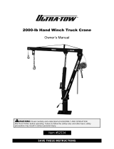
IC-250-3D DIMENSIONS

1-3
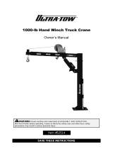
IC-250-3D TURNING DIMENSIONS

1-4
SECTION 1
DESCRIPTION AND SPECIFICATIONS
The IC-250-3D is a self-propelled Industrial Crane designed for material handling and maintenance
and repair of equipment, with special features of self-loading cargo decks, 4-wheel steer, and front-
wheel drive (4-wheel drive optional). The basic unit consists of a chassis and hydraulic boom
assembly. The chassis includes a frame, four hydraulic independently controlled outriggers,
engine, torque converter, powershift 4-speed transmission, front planetary drive/steer axle and rear
steer-only axle, fuel tank, hydraulic tank, control station, power steering and dual power brakes.
The boom assembly includes a hydraulic powered continuous rotation turret, proportional 4-section
telescopic boom, hydraulic boom elevating cylinder, hydraulic boom telescope cylinder and
hydraulic powered hoist. Rated Capacity Limiter (RCL) is standard.
IC-250-3D:
4-section hydraulically extended boom with capacity of 36,000 pounds (16330kg) at a 6-foot
(1.8m) load radius. Horizontal reach of 50.1 feet (15.27m) and vertical reach of 60.6 feet
(18.47m).
General:
Length:
Overall 23.5 feet (7.16m)
Chassis 15.4 feet (4.72m)
Width: 7.8 feet (2.39m)
Height:
Overall 7.9 feet (2.41m)
Deck 47 inches (1.19m)
Wheelbase: 100 inches (2.54m)
Ground Clearance:
Chassis 13 inches (33cm)
Minimum (Tailpipe) 10 inches (25cm)
Angle of Approach: 25 degrees
Angle of Departure: 24 degrees
Outriggers:
Spread 14.7 feet (4.50m)
Penetration 3 inches (76mm)
Boom Movement:
Rotation Continuous
Elevation 0 to 75 degrees
Telescope 34.5 feet (10.52m)
Boom Speeds:
Rotation 1.3 RPM
Elevation 22 seconds
Telescope 41 seconds

1-5
General: (cont’d.)
Extension: W/O Boom Extension With Boom Extension
Sheave Height (Nominal): 60.7 feet (18.47m) 79.5 feet (24.23m)
Horizontal Reach: 50.1 feet (15.27m) 70.1 feet (21.36m)
Weight:
Total 37,700 pounds (17100kg)
Front Axle 17,100 pounds (7800kg)
Rear Axle 20,600 pounds (9300kg)
Turning Radius: (4-Wheel Steering) 14.3 feet (4.37m)
Aisle Width for 90° Turn 11.9 feet (3.63m)
Steering Modes Rear Steer, Round Steer, Crab Steer
Road Speed 19 MPH (30.6km/h)
Cummins 3.3L GM5.7L
Drawbar Pull 17,700 pounds* (8000kg) 21,400 pounds* (9700kg)
Gradeability 64 percent* (33 degrees)
*Calculated, Wheels spin below these values in 2-wheel drive.
Grade Limit 15 percent (9 degrees)
Engine:
Standard:
Cummins QSB3.3L Turbo, EPA Tier 4i:
Cummins QSB3.3 Tier 4 Interim turbocharged diesel engine. Water cooled, 4-cylinder,
199 CID (3.3L), 3.74-inch (95 mm) bore, 4.53-inch (115 mm) stroke, 100 HP (75 kW) at
governed speed of 2600 RPM. Maximum torque is 306 ft-lbs (415 Nm) at 1600 RPM.
120-amp alternator included. 30-gallon (114 L) fuel tank capacity. High temperature and
low oil pressure shutdown included in engine management system. Throttle control switch
for setting engine speed at 1200 or 1800 RPM. Diesel oxidation catalyst muffler; Air
intake pre-cleaner; Charge air cooler; 1500 watt, 120 VAC, block heater; and grid heater
included. Net Weight: 200 pounds (91 kg)
Optional Engines and Engine Accessories:
GM 5.7L V-8 EPA Tier 2 Woodward LPG Fuel:
GM Model 5.7L V-8 industrial LPG engine complete with electronic LPG fuel injection,
and engine management system. Includes water cooled, 350 CI (5.7L) displacement,
bore 4.00” (102mm), stroke 3.48” (88mm), 135 HP (101kw) at governed speed at 2,500
RPM. Maximum torque 307 ft. lbs. (416Nm) at 1,500 RPM. Also includes special
exhaust valves, seats and valve rotators for use with LPG, 100-amp alternator, catalytic
converter, dual 43 pound (19.5kg) LPG tanks with quick disconnect, and high temperature
and low oil pressure shutdown. Throttle control switch for setting engine speed at 1200 or
1800 RPM. US EPA Tier 2 emissions certified. (Net Weight 175 lbs., (79kg) including 2
aluminum LP tanks.)
Spark Arrester Muffler:
Spark arrester muffler used in addition to standard muffler. Net Weight: 10 pounds (5kg)
Engine Heater:
Heater for LPG engine. Standard with diesel engine. Engine coolant heater installed with
hoses in coolant system to circulate warm water through engine. Plugs into 120-volt AC
extension cord: 1,500 watts.

1-6
Transmission:
Standard 2-Wheel Drive:
Powershift transmission with four speeds in forward and reverse. Provides powershifts at
any engine speed in any gear. All shifting is done with a single lever electrical control
mounted on the steering column. Multiple-disc clutch packs operated by solenoid valves
provide reverse, neutral, forward and speed selection. Equipped with oil cooler and filter.
Optional 4-Wheel Drive Transmission:
Same as 2WD transmission with an additional output shaft to drive the rear axle. Rear
output shaft runs faster than front by a ratio of 1.58 to 1. Rear axle has more reduction than
front axle to match speed of front. Electrohydraulic control for shifting between 2WD and
4WD. This option includes the 4-wheel drive axle listed below. (Net Weight: 310 pounds
(141kg) for 4WD system)
Transmission gear ratios: Forward and Reverse (2WD & 4WD)
1st 5.72 to 1.0
2nd 3.23 to 1.0
3rd 1.77 to 1.0
4th 1.00 to 1.0
Torque Converter:
Standard:
Stall torque ratio of 2.2:1, attached to engine flywheel.
Front Axle:
Standard:
Planetary drive/steer front axle with 15.78 to 1.0 ratio. Differential equipped with "limited slip"
feature. Driving effort is applied to wheel that has traction. Front axle mounted rigidly to
frame.
Calculated Performance:
Gear Travel Speeds (MPH) Gradeability* Drawbar Pull
1st 3 65 18,100 pounds (8200kg)
2nd 5 36 10,600 pounds (4800kg)
3rd 10 19 6,000 pounds (2700kg)
4th 18 10 3,200 pounds (1450kg)
*Calculated, wheels may spin in 1st or 2nd gear before these values are reached with 2-
wheel drive.
Rear Axle:
Standard 2-Wheel Drive:
Steering axle with 1½° oscillation in either direction.
Optional 4-Wheel Drive:
Planetary drive/steer axle with 24.98 to 1.0 ratio. Differential is not “limited slip” in rear axle.
1½° oscillation in either direction. (Axle ratio compatible with 4WD transmission rear output
ratio to match front axle speed.)
Steering:
Standard:
Hydraulic steering unit with two 3-inch (7.6cm) cylinders attached to each axle. Allows
limited steering when engine is not running. A switch on the control panel is used to select
rear-wheel steering or four-wheel (round) steering or crab steering.

1-7
Brakes:
Standard:
Split-system, four-wheel hydraulically-boosted multiple-plate wet disc brakes. Uses mineral
oil. Hand lever actuated disc-type parking brake on transmission.
Tires:
Standard 2-Wheel & 4-Wheel Drive:
385/65D22.5, 16-ply, high-traction on/off road tread.
Tire Options:
Foam Filling of Tires:
Foam filling of four IC-250 tires. Net Weight: 2000 pounds (907kg)
Non-Marking Pnuematic:
385/65D22.5 16-ply. Net Weight: 20 pounds (9kg)
Spare Tire and Wheel, Mounted:
Extra wheel with 385/65D22.5 tire mounted, ready for service.
Net Weight: 350 pounds (159kg)
Spare Tire and Wheel, Mounted, Non-Marking Pnuematic:
Extra wheel with Non-Marking 385/65D22.5 tire mounted, ready for service.
Net Weight: 355 pounds (161kg)
Chassis:
Standard:
Cargo Deck:
Total Deck Area: 80 Square feet (7.4m²). Front deck 94” (239cm) X 62” (157cm), RH
side deck 182” (462cm) X 28” (71cm). A maximum of 17,000 pounds (7700kg) may be
carried on the deck when centered over or between axles. Seven stake pockets are
provided along edges of deck for 1-inch (25mm) pipe stakes. Stakes furnished. Cargo
decks have skid resistant coating.
Headlight and Taillight Grilles:
Steel protective grilles for headlights and taillights. Easily removable for replacing bulbs.
Outriggers:
Four hydraulic out-and-down outriggers of box-beam construction. Independent controls
for each outrigger. Hydraulic cylinders are equipped with direct-connected holding valves.
Pad dimensions: 9 inches (23cm) x 9 inches (23cm).
Pulling Eyes:
Two heavy eyes in front bumper provide for attachment of hook block so main winch line
can be used for pulling loads at or near floor level. Also for anchoring tag lines from load
on hook.
Tie Downs:
Two holes in the rear bumper (in conjunction with the pulling eyes) provide tie down
locations for transporting crane by truck or cargo container.
Accessory Storage Box:
Consists of front deck plate with removable and lockable cover, and box for carrying
sheave block and other items. Storage box is 14" (35cm) deep x 12½" (32cm) long x
36½" (93cm) wide.

1-8
Chassis: (cont’d.)
Lifting Rings:
Consists of four rings, one at each corner of the load deck, so sling can be attached for
lifting crane. Rings hang below deck surface when not in use.
Chassis Options and Accessories:
Auxiliary Winch:
Optional worm gear winch, mounted behind front bumper, with a single lever control at the
operator's console. Hydraulic powered to provide bare drum line pull of 10,000 lbs.
(4540kg) at 33 ft. per minute (10.2m/min). Winch drum is 3½" (90mm) dia. by 10"
(250mm) long. This winch includes 115 ft. (35m) of 7/16" (11.1mm) wire rope, hook and
four-way roller guide. This rope can pull 5800 pounds (2360kg) with a safety factor of
3.5:1. Net Weight: 250 pounds (113kg)
Pintle Hook - Rear:
T-60-AOL Holland pintle hook mounted on rear frame member, provides capacity for
6,000 pound (2700kg) tongue weight and 30,000 pound (13600kg) trailer weight. Net
Weight: 15 pounds (7kg)
Pintle Hook - Front:
T-60-AOL Holland pintle hook mounted on front frame member, provides same capacity
as rear pintle hook. Net Weight: 45 pounds(20kg)
Outrigger Shoes:
Steel outrigger shoes, 18 X 18 inch (46 x 46cm) octagonal shape with storage posts on
rear bumper. Net Weight: 170 pounds (77kg)
Rearview Mirrors:
One right-hand and one left-hand mirror, 6" (152mm) wide x 16" (406mm) high, mounted
on deck stakes. Pivot out of way when contacted by obstacle at side of deck. Net
Weight: 12 pounds (5kg)
Operator Compartment:
Standard:
Operator control station provides one-position access to all chassis and crane
functions.Includes adjustable operator's seat and seat belt.
Drum Rotation Indicator:
Provides tactile feedback to operator when hoist drum is rotating. Feedback device
attached to hoist control handle Feedback is proportional to hoist speed.
Operator Compartment Options and Accessories:
Operator Guard: (Not Available with Cab)
Tubular steel weldment with heavy expanded steel mesh top section, bolts over the
operator's compartment. Operator Guard is not designed, rated or certified as a
Falling Objects Protection System (FOPS) or Rollover Protection System (ROPS). Net
Weight: 60 pounds (27kg)
Operator Guard Door:
Hinged door covers operator compartment side opening. Has latch handle outside
and knob inside. Rubber gasket contacts chassis. Net Weight: 40 pounds (18kg)
All Weather Cab:
Consists of rigid mounted canopy section and removable hinged door with safety
glass. Rugged canopy structure with laminated glass front and top. Door is equipped
with a keyed lock to protect operator's station. Includes defroster fan, dome light,
12,400 BTU heater with 2-speed fan and 12V electric windshield wiper. There are
sliding windows in the door and right-hand side. Net Weight: 220 pounds (98kg)

1-9
Operator Compartment Options and Accessories: (cont’d.)
Cab Heater only:
Provides 12,400 BTU heater with two-speed fan for units without All Weather Cab.
Net Weight: 12 pounds (5kg)
Windshield Washer:
Provides reservoir, pump and nozzle for windshield washer
Floor Mat:
Vinyl mat with foam backing covers floor, front wall and lower portion of right hand wall
of operator’s compartment. Net Weight: 5 pounds (2kg))
Operator’s Suspension Seat:
Vinyl seat with small suspension built in. Net Weight: 15 pounds (7kg)
Noise Reduction Kit - Cab:
Includes vinyl floor mats and control valve cover and side panels of foam-backed,
perforated vinyl for noise reduction. Net Weight: 15 pounds (7kg)
Deluxe Seat:
Deluxe seat with upholstery springs provides additional operator comfort. Net
Weight: 15 pounds (7 kg)
Air Conditioning:
Provides factory system using R134A refrigerant. Compact AC unit mounted in
operators area, fan cooled condenser mounted under fuel tank and belt driven
compressor with magnetic clutch driven by engine. Net Weight 125 lbs. (57kg)
Electrical System:
Standard 12 Volt DC:
Battery:
Diesel Units: Group 31 with 950 CCA rating.
LP Units: Group 27 with 540 CCA rating.
Lighting Group:
Consists of two 12V-lamps, with high and low beams for driving; tail, brake and turn signal
lights and backup lights in rear; front turn signals and emergency flasher switch at
operator's station. 12V horn actuated by button located on shifting control.
Instrument Group:
Located at operator's station, includes fuel gauge and hourmeter which records hours
only during actual engine operation. Also included are warning lights for low oil and
transmission pressure, check engine, high coolant and transmission temperature, turn
signals, high beams, hazard lights, parking brake and four-wheel drive.
Back-Up Alarm:
Provides pulsating sound from a 102 dB alarm when ignition is on and transmission is in
reverse. Conforms to SAE J994B.
Outrigger Alarm System:
102 dB alarm with alternating two-tone sound is actuated by a switch when the
OUTRIGGER DOWN or OUTRIGGER OUT controls are operated.

1-10
Optional Electrical Accessories:
Strobe Lights:
Two yellow strobe lights, one on each side of turret weight box, for high visibility all around
crane. Flashes 60-120 times per minute. Each strobe draws only one-half amp.
Includes operator controlled switch. Net Weight: 5 pounds (2kg)
Boom Work Lights:
Two halogen work lights, one on left side of boom to light boom tip, and one on right side
of the turret to light ground under boom tip. Includes switch at operator's station. Net
Weight: 10 pounds (5kg)
Hydraulic System:
Standard:
Tandem pump, direct-driven by engine, delivers 30 GPM (113L/min) at 3,000 PSI (207bar)
and 35 GPM (132L/min) at 2,500 PSI (172bar) at 2,500 RPM governed engine speed.
System protected by relief valves, suction line strainer and 10-micron return line filter. 54-
gallon (204L) reservoir equipped with breather and filler cap. Maximum flows with LP only
engine at 2500 RPM goverened speed are 29 GPM (110L/min) and 34 GPM (129L/min).
Boom Assembly:
Standard:
Four-section, high strength steel construction, equipped with bearing pads for efficient
support and extension. Double-acting hydraulic cylinder and chain system telescopes boom
sections proportionally. The telescope cylinder and the double-acting boom elevation
cylinders are equipped with cylinder-mounted holding valves. Boom angle indicators are on
each side of boom.
Boom Rotation:
Standard:
Heavy-duty bearing rotation gear with external teeth supports boom. Rotation is powered by
hydraulic motor and worm gear drive. Rotation gearbox may be adjusted as wear occurs to
minimize backlash. Boom is attached by steel weldment.
Boom Hoist:
Standard:
Turret-mounted planetary gear hoist, is hydraulically powered to provide a bare-drum line pull
of 12,000 pounds (5440kg) and a speed of 100 feet per minute (30m/min). Hoist drum is 9
7/8-inch (251mm) diameter by 16½ inches (419mm) long. The hoist includes 320 feet (97m)
of 9/16 inch (14mm) wire rope, 170 pound (77kg) downhaul weight and swivel hook.
Boom Attachments:
Standard:
Anti-Two-Block Device:
Prevents damage to hoist rope and/or machine components from accidentally pulling
sheave block or downhaul weight against boom tip. Consists of trip arm at boom tip
which is moved upward by sheave block or downhaul weight as hook approaches boom
tip. Trip arm actuates electric switch which is connected through cable reel mounted on
turret to solenoid dump valve in the hydraulic circuit. This valve will dump the HOIST
RAISE, TELESCOPE EXTEND, BOOM LOWER, SWING LEFT and SWING RIGHT
circuits. No other circuits are affected. These circuits are returned to normal operation by
operating the HOIST LOWER or TELESCOPE RETRACT control.

1-11
Rated Capacity Limiter:
Operational aid that warns operator of impending overload with audible and visual signals.
Has read-outs for load, boom angle, boom length and load radius. In the event of an
overload, dumps the following boom functions: HOIST RAISE, TELESCOPE EXTEND,
BOOM LOWER, SWING LEFT and SWING RIGHT. These circuits are returned to
normal by lowering load to a safe resting place with hoist or by retracting or raising boom
to a shorter load radius. There is a key-operated override switch under the dashboard.
Four-Part-Line Sheave Block:
Double sheave block for four-part-line requirements. 10-inch (254mm) OD sheaves for
9/16 inch (14mm) diameter wire rope. Swivel hook with safety latch. 300 pound (136kg)
weight provides positive overhaul. Includes bar on top to actuate trip arm of Anti-Two-
Block Device.
Optional Boom Attachments:
Boom Extension - 20 Ft. (6.1m) Offset:
Provides 20 feet (6.1m) of additional length for lifting loads with load line. Boom
extension may be stowed alongside base boom section when not in use. Tip sheave,
attaching brackets and pins included. Deduct 500 pounds (220kg) from Capacity Chart
when boom extension is in the stowed position. Includes trip arm for Anti-Two-Block
Device. Boom extension will tilt through three positions: in-line, 15 degree offset and 30
degree offset. Net Weight: 680 pounds (308kg)
Searcher Hook: (Four-Pin)
5,000 pound (2270kg) capacity hook bracket is attached to the front of the boom tip with
four pins through the attachment lugs. A swivel hook with latch is pinned to the tip of the
bracket. Net Weight: 65 pounds (29kg)
Two-Part-Line Sheave Block:
Sheave block for two-part-line requirements. 10-inch (254mm) OD sheave for 9/16 inch
(14mm) wire rope. Swivel hook with safety latch. 200 pound (91kg) weight provides
positive overhaul. Includes bar on top to actuate trip arm of anti-two-block device. Net
weight: 200 pounds (91kg)
*** Specifications subject to change without notice ***


2-1
OPERATION SECTION
SAFETY RULES
GENERAL:
1. Since the manufacturer has no direct control over machine application and operation,
conformance with good safety practice is the responsibility of the user and his operating
personnel.
2. 3.
4. The operator shall be responsible for those operations under his direct control. Whenever
there is any doubt as to safety, the operator shall have the authority to stop and refuse to
handle loads until safety has been assured.
5. The operator shall not engage in any practice which will divert his attention while actually
operating the crane.
6. Do not run the engine in an enclosed area or indoors without adequate ventilation.
7. Do not use ether for starting. Ether is highly flammable and can be ignited by the intake
manifold heater grid, causing engine damage or operator injury.
8. This list of rules is only a supplement to all federal, state, and local safety rules that may
apply.
CRANE CONDITION:
1. Before beginning operation each day, thoroughly inspect the entire crane to be sure it is in
good operating condition.
2. Inspect load hoist rope and wedge socket daily. We recommend rope inspection,
replacement and maintenance in accordance with ANSI B30.5, Sec. 5-2.4.

2-2
3. Keep operator's compartment and decks free of mud and grease.
4. If crane is equipped with a cab, keep all window glass clean. Keep gauges clean.
5. Tools, lubricants, or rags on the crane should be kept in a secured toolbox.
6. 7.
8. The Rated Capacity Limiter must be checked before each shift and after each setup for the
proper operating configuration on the display. It must be inspected before each shift and
tested with a known load at least once a month as described in the RCL operation manual.

2-3
LIFTING:
1. Always refer to Crane Capacity Chart in operator's compartment before handling load. Do
not exceed load ratings. Under some conditions the standard capacity ratings cannot be
recommended and must be adjusted downward to compensate for special hazards, such
as weak supporting ground, wind, hazardous surroundings, operator inexperience, etc.
The weight of the load should always be known.
2. Be careful to prevent load swinging. A swinging load can cause instability or loss of control
of the load. Be aware that the Anti-Two-Block System and the Rated Capacity Limiter can
cause sudden stopping of boom movement, which can cause the load to swing. Swing the
boom slowly whenever these systems might stop the boom.
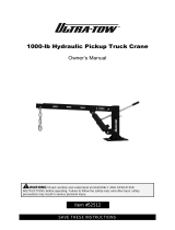
3. Do not allow anyone to put
any part of his body under a
load. The load may lower or
fall if there are damaged
parts in the crane. Also, the
load may drop a short
distance due to thermal
contraction of the hydraulic
oil in the cylinders.
4. Do not use crane to drag loads sideways. Do not use crane to raise grounded or fixed load
by using Boom Raise function.
5. 6.
7. Level the crane before lifting. A small incline will significantly reduce the capacity. Use
appropriate cribbing under the outriggers for leveling. All outrigger beams must be fully
extended and tires must clear the ground to use the OUTRIGGERS OUT & DOWN ratings.
8. Always use outriggers if possible. If you must lift on rubber, keep the load as close to the
ground as possible to prevent tipover. Move the load very slowly and use tag lines to
prevent load swinging.

2-4
9. Crane may tip at less than rated loads if the surface is uncompacted or wet dirt, or soft soil
with frozen crust, thin or cracked pavement, or surface near a hole or ledge. Always use
adequate outrigger floats and/or cribbing. See page 2-15.
10.The operator shall not leave the controls while the load is suspended.
11. Always use adequate parts of load hoist line for lifting heavy loads.
12. Always be sure the rope is properly seated and wound evenly on hoist drum.
13. Keep hands away from load hoist rope when hoist is being operated.
14. Be sure at least three wraps of rope are left on the hoist drum to ensure against rope pulling
out of its anchor.
15. Never wrap the hoist rope around a load. Always use approved rigging.
16. Avoid pinch points such as between a rotating turret and the cab, or in access holes of a
telescoping boom, or between the two-block mechanism.
/