LG ABNW30GM1E4 Installation guide
- Category
- Split-system air conditioners
- Type
- Installation guide

www.lg.com
Copyright © 2022 - 2023 LG Electronics Inc. All Rights Reserved.
INSTALLATION MANUAL
AIR
CONDITIONER
Please read this installation manual completely before installing the product.
Installation work must be performed in accordance with the national wiring standards by
authorized personnel only.
Please retain this installation manual for future reference after reading it thoroughly.
Ceiling Concealed Duct
MFL67939944
Rev.07_020823
ENGLISH

ENGLISH
TABLE OF CONTENTS
2
3TIPS FOR SAVING ENERGY
4IMPORTANT SAFETY INSTRUCTIONS
7INTRODUCTION
7Features
8INSTALLATION OF INDOOR
8Selection of the best location
8Installation of Unit
11 Indoor Unit Drain Piping
11 Drain test
12 Thermal Insulation
13 ELECTRIC WIRING WORK
13 General instructions
13 Wiring Connection
15 INSTALLATION INSTRUCTION
18 Remote controller installation
19 Group Control
20 How to enter the setting mode
21 Installer Setting - Central Control Address Setting
22 Installer Setting - Wired Controller Master / Slave Setting
23 Installer Setting - Static Pressure Step Setting
24 Installer Setting - Static Pressure Setting
25 Installer Setting - E.S.P Setting
26 Installer Setting - Thermistor
27 Installer Setting - Test Run Mode
28 Installer Setting - Celsius Setting
29 Installer Setting - Auto ESP
47 DIP SWITCH SETTING
TABLE OF CONTENTS

• Do not cool excessively indoors. This may be harmful for your health and may consume more
electricity.
• Block sunlight with blinds or curtains while you are operating the air conditioner.
• Keep doors or windows closed tightly while you are operating the air conditioner.
• Adjust the direction of the air flow vertically or horizontally to circulate indoor air.
• Speed up the fan to cool or warm indoor air quickly, in a short period of time.
• Open windows regularly for ventilation as the indoor air quality may deteriorate if the air
conditioner is used for many hours.
• Clean the air filter once every 2 weeks. Dust and impurities collected in the air filter may block the
air flow or weaken the cooling / dehumidifying functions.
For your records
Staple your receipt to this page in case you need it to prove the date of purchase or for warranty
purposes. Write the model number and the serial number here:
Model number :
Serial number :
You can find them on a label on the side of each unit.
Dealer’s name :
Date of purchase :
Here are some tips that will help you minimize the power consumption when you use the
airconditioner. You can use your air conditioner more efficiently by referring to the instructions
below:
TIPS FOR SAVING ENERGY
3
ENGLISH
TIPS FOR SAVING ENERGY

ENGLISH
IMPORTANT SAFETY INSTRUCTIONS
4
IMPORTANT SAFETY INSTRUCTIONS
READ ALL INSTRUCTIONS BEFORE USING THE APPLIANCE.
Always comply with the following precautions to avoid dangerous situations and ensure peak
performance of your product
WARNING
It can result in serious injury or death when the directions are ignored
CAUTION
It can result in minor injury or product damage when the directions are ignored
WARNING
• Installation or repairs made by unqualified persons can result in hazards to you and others.
• Installation work must be performed in accordance with the National Electric Code by
qualified and authorized personnel only.
• The information contained in the manual is intended for use by a qualified service technician
familiar with safety procedures and equipped with the proper tools and test instruments.
• Failure to carefully read and follow all instructions in this manual can result in equipment
malfunction, property damage, personal injury and/or death.
Installation
• Always perform grounding.
- Otherwise, it may cause electrical shock.
• For installation of the product, always contact the service center or a professional installation
agency. - Otherwise, it may cause a fire, electrical shock, explosion or injury.
• Securely attach the electrical part cover to the indoor unit and the service panel to the outdoor unit.
- If the electrical part cover of the indoor unit and the service panel of the outdoor unit are not
attached securely, it could result in a fire or electric shock due to dust, water, etc.
• Always install an earth leakage circuit breaker and a dedicated switching board. - No installation may
cause a fire and electrical shock.
• Do not keep or use flammable gases or combustibles near the air conditioner. - Otherwise, it may
cause a fire or the failure of product.
• Ensure that an installation frame of the outdoor unit is not damaged due to use for a long time.
- It may cause injury or an accident.
• Do not disassemble or repair the product randomly. - It will cause a fire or electrical shock.
• Do not install the product at a place that there is concern of falling down. - Otherwise, it may result
in personal injury.
• Use caution when unpacking and installing. - Sharp edges may cause injury.
• Use a vacuum pump or Inert (nitrogen) gas when doing leakage test or air purge. Do not compress
air or Oxygen and Do not use Flammable gases. Otherwise, it may cause fire or explosion. There is
the risk of death, injury, fire or explosion.
• Consult your local dealer regarding what to do in case of refrigerant leakage.
When the air conditioner is to be installed in a small room, it is necessary to take proper measures
so that the amount of any leaked refrigerant does not exceed the concentration limit in the event of
a leakage. Otherwise, this may lead to an accident due to oxygen depletion.
• Carry out the specified installation work after taking into account earthquakes.
Failure to do so during installation work may result in the unit falling and causing accidents.
!
!
!

IMPORTANT SAFETY INSTRUCTIONS
ENGLISH
5
• Make sure that a separate power supply circuit is provided for this unit and that all electrical wo
carried out by qualified personnel according to local laws and regulations and this installation
manual. An insufficient power supply capacity or improper electrical construction may lead to
electric shocks or fire.
• Be sure to switch off the unit before touching any electrical parts.
• Make sure that all wiring is secured, the specified wires are used, and that there is no strain on the
terminal connections or wires.
• If refrigerant gas leaks during installation, ventilate the area immediately.
Toxic gas may be produced if the refrigerant gas comes into contact with fire.
• If the supply cord is damaged, it must be replaced by the manufacturer, its service agent or similarly
qualified persons in order to avoid a hazard.
• The plug accessible have to be accessible for disconnection of the appliance. or means for
disconnection must be incorporated in the fixed wiring in accordance with the wiring rules.
• The appliance shall be installed in accordance with national wiring regulations.
• This appliance incorporates an earth connection for functional purposes only
Operation
• Turn off the unit if strange sounds, smell, or smoke comes from it. - Otherwise, it may cause
electrical shock or a fire.
• Keep the flames away. - Otherwise, it may cause a fire.
• Do not touch the power cable with wet hands when it taking out . - Otherwise, it may cause a fire or
electrical shock.
• Do not open the suction inlet of the indoor/outdoor unit during operation. - Otherwise, it may
electrical shock and failure.
• Do not allow water to run into electrical parts. - Otherwise, it may cause the failure of machine or
electrical shock.
• Never touch the metal parts of the unit when removing the filter. - They are sharp and may cause
injury.
• Do not step on the indoor/outdoor unit and do not put anything on it. - It may cause an injury through
dropping of the unit or falling down.
• When the product is submerged into water, always contact the service center. - Otherwise, it may
cause a fire or electrical shock.
• Take care so that children may not step on the outdoor unit. - Otherwise, children may be seriously
injured due to falling down.
• This appliance is not intended for use by persons (including children) with reduced physical, sensory
or mental capabilities or lack of experience and knowledge, unless they have been given supervision
or instruction concerning use of the appliance by a person responsible for their safety. Children
should be supervised to ensure that they do not play with the appliance.
• This appliance can be used by children aged from 8 years and above and persons with reduced
physical, sensory or mental capabilities or lack of experience and knowledge if they have been given
supervision or instruction concerning use of the appliance in a safe way and understand the hazards
involved. Children shall not play with the appliance. Cleaning and user maintenance shall not be
made by children without supervision.

6IMPORTANT SAFETY INSTRUCTIONS
ENGLISH
CAUTION
Installation
• Install the drain hose to ensure that drain can be securely done. - Otherwise, it may cause water
leakage.
• Install the product so that the noise or hot wind from the outdoor unit may not cause any damage to
the neighbors. - Otherwise, it may cause dispute with the neighbors.
• Always inspect gas leakage after the installation and repair of product. - Otherwise, it may cause the
failure of product.
• Keep level parallel in installing the product. - Otherwise, it may cause vibration or water leakage.
• Do not install the unit in potentially explosive atmospheres.
• Always install a dedicated circuit and breaker.
- Improper wiring or installation may cause fire or electric shock.
Operation
• Avoid excessive cooling and perform ventilation sometimes. - Otherwise, it may do harm to your
health.
• Use a soft cloth to clean. Do not use wax, thinner, or a strong detergent. - The appearance of the air
conditioner may deteriorate, change color, or develop surface flaws.
• Do not use an appliance for special purposes such as preserving animals vegetables, precision
machine, or art articles. - Otherwise, it may damage your properties.
• Do not place obstacles around the flow inlet or outlet. - Otherwise, it may cause the failure of
appliance or an accident.
• Do not turn on the breaker or power under condition that front panel, cabinet, top cover, control box
cover are removed or opened.
!

INTRODUCTION
ENGLISH
7
Features
INTRODUCTION
Remote
Controller
Air inlet vents
Air outlet
vents

Installation of Unit
Install the unit above the ceiling correctly.
Position of suspension Bolt
- Apply a joint-canvas between the unit and
duct to absorb unnecessary vibration.
- Apply a filter Accessory at air return hole.
CASE 1
M1/M2/M3 Chassis
According to product region, Capacity and chassis are applicable, Please refer below table.
Front view
Unit: mm
H = 20 mm or more
Front
Inspection hole
600 x 600
Control box
1000 600
Air outlet vents
Air inlet vents
Top view
Unit: mm
8INSTALLATION OF INDOOR
ENGLISH
Drainage hole
CE
G
D
F
I
A
J
B
H
Internal Unit Roof
Flexible
Flexible
discharge
discharge
pipe
pipe
Air outlet
Ceiling Panel
Check port
Ceiling Panel
Cloth tube
Suction
Suction
tube
tube
Flexible
discharge
pipe
Suction
tube
Outlet air intake
(Unit:mm)
Selection of the best location
- The place shall easily bear a load exceeding
four times the indoor unit’s weight.
- The place shall be able to inspect the unit as
the figure.
- The place where the unit shall be leveled.
- The place shall allow easy water drainage.
(Suitable dimension “H” is necessary to get
a slope to drain as figure.)
- The place shall easily connect with the
outdoor unit.
- The place where the unit is not affected by
an electrical noise.
- The place where air circulation in the room
will be good.
- There should not be any heat source or
steam near the unit
- Confirm the positional relationship between
the unit and suspension bolts.
- Thermal insulator the ceiling opening to
clean the filter or service under the product.
INSTALLATION OF INDOOR
Common
(T2 Series) (T6 Series) (T5 Series) Chassis Dimension
A B C D E F G H I J
18k, 24k 18k, 21k, 24k,
27k, 28k, 30k 18k, 24k M1
933.4 971.6 619.2 691 30 270 15.2 858 201.4 900
30k - - M2
1283.4 1321.6
619.2 691 30 270 15.2 1208 201.4 1250
36k, 42k, 48k,
54k, 60k
34k, 36k, 40k, 48k,
50k, 53k, 55k, 60k
30k, 36k, 48k,
60k M3
1283.4 1321.6
619.2 691 30 360 15.2 1208 291.4 1250

INSTALLATION OF INDOOR
ENGLISH
9
- Select and mark the position for fixing bolts.
- Drill the hole for set anchor on the face of
ceiling.
- Insert the set anchor and washer onto the
suspension bolts for locking the suspension
bolts on the ceiling.
- Mount the suspension bolts to the set
anchor firmly.
- Secure the installation plates onto the
suspension bolts (adjust level roughly) using
nuts, washers and spring washers.
- Install the unit leaning to a drainage hole side
as a figure for easy water drainage.
Position of console Bolt
- A place where the unit will be leveled and
that can support the weight of the unit.
- A place where the unit can withstand its
vibration.
- A place where service can be easily
performed.
CASE 2
M10 Nut
M10 SP. washer
M10 washer
X 4
X 4 (Local
supply)
X 4
M10 Nut
M10 SP. washer
M10 washer X 4
X 4 (Local
supply)
X 4
1
Old building New building
2
3
4
5
Set anchor
Plate washer
Spring washer
Nut
Suspension
bolts
CAUTION
Tighten the nut and bolt to prevent unit
falling.
!
(Unit:mm)
(S2 Series) (T4 Series) (E4 Series) Chassis Dimension
A B C D E F G H I J
18k, 24k, 30k 18k, 24k, 30k 24k,30k M1
933.4 971.6 619.2 691 30 270 15.2 858 201.4 900
- - 36k M2
1283.4 1321.6
619.2 691 30 270 15.2 1208 201.4 1250
36k, 48k, 60k 36k, 48k, 54k, 60k - M3
1283.4 1321.6
619.2 691 30 360 15.2 1208 291.4 1250

10 INSTALLATION OF INDOOR
ENGLISH
CAUTION
• Install declination of the indoor unit is very important for the drain of the duct type air
conditioner.
• Minimum thickness of the insulation for the connecting pipe shall be 5mm.
Front of view
• The unit must be declined to the drain hose connected when finished installation.
!
Ceiling
Drainage hole Drainage hole
CORRECT INCORRECT
5~10mm
Drainage hole
U-Trap
B
C
A ≥ 70 mm
B ≥ 2C
C ≥ 2 x SP
SP = External Pressure
(mmAq)
Ex) External Pressure
= 10 mmAq
A ≥ 70 mm
B ≥ 40 mm
C ≥ 20 mm
A
Make sure to be closed.
Unit
Unit
Thermal insulator
(Local supply)
Drainage pipe
(Local supply)
• Always lay the drain with downward
inclination (1/100 to 1/50).
Prevent any upward flowor reverse
flow in any part.
• 10 mm or thicker formed thermal
insulator shall always be provided
for the drain pipe.
• Install the P-Trap (or U-Trap) to
prevent a water leakage caused
by the blocking of intake air filter.
Applied U-Trap Dimension
CORRECT INCORRECT
• Upward routing
not allowed
Caution for gradient of unit and drain piping
Lay the drain hose with a downward inclination so water will drain out.

INSTALLATION OF INDOOR
ENGLISH
11
Indoor Unit Drain Piping
- Drain piping must have down-slope (1/50 to
1/100): be sure not to provide up and down
slope to prevent reversal flow.
- During drain piping connection, be careful
not to exert extra force on the drain port on
the indoor unit.
- The outside diameter of the drain connection
on the indoor unit is 32 mm.
Piping material: Polyvinyl chloride pipe VP-25
and pipe fittings
- Be sure to execute thermal insulator on the
drain piping.
- Install the drain raising pipes at a right angle
to the indoor unit and no more than 300 mm
from the unit.
Thermal insulator material: Polyethylene foam
with thickness more than 8 mm.
Drain test
- Connect the main drain pipe to the exterior
and leave it provisionally until the test comes
to an end.
- Feed water to the flexible drain hose and
check the piping for leakage.
- When the test is complete, connect the
flexible drain hose to the drain port on the
indoor unit.
1Remove the air filter.
2Check the drain.
- Spray one or two glasses of water upon
the evaporator.
- Ensure that water flows drain hose of
indoor unit without any leakage.
Feed water
Flexible drain hose
(accessory)
Main
drain pipe
Glue the join
t
Air filters
Maintenance
drain port
Upward
routing
not allowed
Pipe clamp
Indoor unit

12 INSTALLATION OF INDOOR
ENGLISH
Thermal Insulation
- Loosen the flare nut of the indoor unit's piping connection port, insert it into the liquid pipe and
the gas pipe, and then conduct flaring work on the ends of each pipe.
- Insulate each of the liquid pipes and gas pipes using insulation material for piping.
hNormal conditions: Temperature of 30 °C, relative humidity of 85 %
hUnfavorable conditions: Temperature of 30 °C, relative humidity of 90 % (humid places such as
bathrooms, swimming pools, etc.: air supply and exhaust fan installation)
Power
cable
Separate
Communication
cable
Fully insulate the connection parts.
Piping insulation
Piping
insulation
Indoor unit
main body
Adhere so that
there are no gaps.
Band Have them
overlap.
ⒶLiquid piping
Ⓑ Gas piping
Ⓒ Power cable
Ⓓ Insulation material
Ⓔ Communication cable
- do the insulation work as it is
showing below (piping insulation
must be at least 19 mm thick)
Applies to
Insulation material
standard (mm)
(besides normal
conditions for residential
use)
Insulation material Standard (mm) -
residential Insulation
material
standard
(mm)
(unfavorable
conditions)
If installed in an
airconditioned place
(CASE 1)
(ex: bedroom, living
room, etc.)
If installed in a non
air conditioned
place (CASE 2)
(ex: hallway,
outdoors, etc.)
Refrigerant
piping
dimensions
(mm)
EPDM EPDM EPDM EPDM
Gas piping
6.35
9.52
12.7
15.88
19.05
22.22
25.40
28.58
31.75
38.1
44.45
19
19
19
19
19
19
19
19
19
25
25
13
13
13
13
13
13
19
19
19
19
19
19
19
19
19
19
19
19
19
19
25
25
19
25
25
25
25
32
32
32
32
32
32
Liquid piping
6.35
9.52 9 9 9 9
12.7 ~ 44.45 13 13 13 13

ELECTRIC WIRING WORK
ENGLISH
13
Wiring Connection
- Open the control box cover and connect the
Remote controller cable and Indoor power
wires.
CAUTION
• For wiring, use the designated power
wire and connect firmly, then secure to
prevent outside pressure being exerted
on the terminal block.
• Use an appropriate screwdriver for
tightening the terminal screws. A
screwdriver with a small head will strip
the head and make proper tighterning
impossible.
• Over-tightening the terminal screws
may break them.
When none are available, follow the
instructions below.
• Do not connect wiring of different
thicknesses to the power terminal
block. (Slack in the power wiring may
cause abnormal heat.)
• When connecting wiring which is the
same thickness, do as shown in the
figure below.
Precautions when laying power wiring
Use round pressure terminals for
connections to the power terminal block.
!
Round pressure terminal Power wiring
Remote
controler
cable
Connection cable between the
indoor unit and the outdoor unit
Control
terminal board
Control
box
A
Wiring Connection
Connect the wires to the terminals on the
control board individually according to the
out
door unit connection.
Ensure that the color of the wires of outdoor
unit and the terminal No. are the same as
those of indoor unit respectively.
ELECTRIC WIRING
WORK
General instructions
- All field supplied parts and materials, electric
works must conform to local codes. Use
copper wire only.
- Follow the "WIRING DIAGRAM” attached to
the unit body to wire the outdoor unit, indoor
units and the remote controller.
- All wiring must be performed by an
authorized electrician.
1(L) 2(N) 3
Connected to
outdoor unit or B.D. unit.
• The feature may be changed according to
the type of model.

14 ELECTRIC WIRING WORK
ENGLISH
A view
Control box cover
(On which the Electric
Wiring Connection is put)
ڸ
ڸ
ڸ
- Remove the control box cover for electrical
connection between the indoor and outdoor
unit. (Remove screws ①.)
- Use the cord clamper to fix the cable.
• The connecting cable connected to the
indoor and outdoor unit should be
complied with the following
specifications (Rubber insulation, type
H05RN-F approved by HAR or SAA).
20 mm
GN/YL
NORMAL
CROSS-SECTIONAL
AREA 0.75 mm2
CAUTION
!
Rated current of
appliance A.
Nominal
cross-sectional area
mm2
≤0.2
> 0.2 and ≤3
> 3 and ≤6
> 6 and ≤10
> 10 and ≤16
> 16 and ≤25
> 25 and ≤32
> 32 and ≤40
> 40 and ≤63
Tinsel cord
0.5
0.75
1.0 (0.75)
1.5 (1.0)
2.5
4
6
10
NOTE For supply cords supplied with
multi-phase appliances, the nominal
cross-sectional area of the conductors is
based on the maximum cross-sectional area
of the conductors per phase at the supply
cord connection to the appliance terminals.
• If the supply cable is damaged, it must be
replaced by a special cable or assembly
available from the manufacturer of its
service agent. When the connection line
between the indoor unit and outdooor unit
and outdoor unit is over 40 m, connect the
telecommunication line and power line
separately.
•
Supply and communication cable of
appliances shall not be lighter than
polychloroprene sheathed. (code
designation 60245 IEC 57)
• Pipes and wires should be purchased
separately for installation of the product.
Using the remote controller
You can operate the air conditioner more
conveniently with the remote controller.
You will find the buttons for the additional
functions under the cover of the remote control.

INSTALLATION INSTRUCTION
ENGLISH
15
INSTALLATION INSTRUCTION
1 Please install the wired controller mounting
plate to the position you want with the
screws provided.
- Do not bend the mounting plate during
installation, as it may cause poor fixing.
Please install a wired controller with a
mounting box (if any) properly. (The
installation box shall be type 86)
Installation box (type 86)
2The connection cables of the wired
controller can be set from two directions:
- Installation direction: slotted on the wall
surface, underside.
- If install a wired control cable from the
guide slot below, please remove the slot
after installation.
* Remove the guide slot with long nose plier
①Slotted on the wall surface
②Underside guide slot
<Cable slot>
ڸ
ڹ
ڹ

16 INSTALLATION INSTRUCTION
ENGLISH
3Please fix remote controller upper part into
the backplate attached to the surface of
the wall, as the picture below, and then,
connect with backplate by pressing lower
part.
- Please make sure to leave no gaps on the
top, bottom, left or right sides between
the remote controller and backplate.
- Before assembly with the backplate,
arrange the Cable not to interfere with
circuit parts.
Remove remote controller by inserting a
screwdriver into the lower separating holes
and twisting to release the controller from
backplate.
- There are two separating holes. Please
individually separate one at a time.
- Please be careful not to damage the
inside components when separating.
4Please refer to the following directions
when connecting the indoor unit and the
wired remote controller together.
- Please connect the cables as shown in
the figure below when connecting the
plug type cable from the indoor unit’s
C/BOX and the housing type of the
extension cable.
5Please use an extension cable if the
distance between the wired remote
controller and the indoor unit is longer than
32 ft(10 m).
Wall
Side
Wall
Side
<Connecting order>
Please check if the connectors
are connected properly.
C/BOX Cable (Plug type)
Extension cable(housing type)
Indoor
Unit
side
Wall
Side
Wall
Side
<Separating order>
CAUTION
• Specification of LG supplied extension
cable: AWG#22, 3 core shielded.
(Model : PZCWRC1)
* Apply enclosed noncombustible conduit
(metal raceway) totally or use FT-6 rated
cable or above level in case of local
electric & building code that requires
plenum (CMP) cable usage.
!
CAUTION
• Installation work must be performed in
accordance with the national wiring
standards and local by authorized
personnel only.
• Installations must comply with the
applicable local/national or international
standards.
• AWG#22, 3 core shielded is
recommended when using the large hole
in the center of the back plate.
• AWG#24, 3 core shielded is
recommended when using the side or
top knock-out of the back plate.
!
Signal Yellow
12 V Red
GND Black

INSTALLATION INSTRUCTION
ENGLISH
17
YELLOW RED BLACK
Signal 12 V GND
Remote
controller PCB
Indoor unit
side
Remote controller
PCB Terminal block
Remark
Indoor
Terminal
block
Function
YELLOW YL Signal
RED RD 12 V
BLACK BK GND
<Remote controller> <Indoor Terminal Block>
CAUTION
• When installing the wired remote
controller, do not bury it in the wall.
(It can cause damage in the temperature
sensor.)
• Do not install the cable to be 164 ft(50
m) or longer. (It can cause
communication error.)
!
1.378 inch(35 mm)
±0.197 inch(5 mm)
0.394 inch(10 mm) ± 0.118 inch(3 mm)
- When connecting Terminal Blocks of the
indoor C/BOX and the wired remote
controller with the extension cable, refer
to the steps below.
①Remove the screw on the cable which
is fastened to the wired remote
controller’s Terminal Block by loosening
with a screw driver.
②Remove the housing of the provided 32
ft extension cable with a cutting nipper
and peel it as shown in the figure
below. (when purchasing the extension
cable at the site directly, please peel it
as shown in the figure below.)
③Make sure each wire is securely
fastened under each screw terminal and
the wires are not in contact with each
other.
④Please connect the Terminal blocks of
indoor unit’s C/BOX and wired remote
controller by referring to the images and
contents shown below. Connect the
yellow(signal) part of the wired remote
controller’s terminal block and the ‘YL’
part of the indoor unit’s terminal block.
Connect the red(12 V) part of the wired
remote controller’s terminal block and
the ‘RD’ part of the indoor unit’s
terminal block. Connect the black(GND)
part of the wired remote controller’s
terminal block and the ‘BK’ part of the
indoor unit’s terminal block.
* In case of loosened screws or insufficient
contact between the terminal and the wire,
remote controller may not function properly.
* When the power is off on the remote
controller, check the connection between
the remote controller and Terminal Block.
* Use an appropriate screwdriver for
tightening the terminal screws. A
screwdriver with a small head will strip the
head and make proper tightening
impossible.
* Over-tightening the terminal screws may
break wires and terminal block structure.

18 INSTALLATION INSTRUCTION
ENGLISH
Remote controller installation
Since the room temperature sensor is in the remote controller, the remote controller box should
be installed in a place away from direct sunlight, high humidity and direct supply of cold air to
maintain proper space temperature. Install the remote controller about 5 ft(1.5 m) above the floor
in an area with good air circulation at an average temperature.
Do not install the remote controller where it can be affected by:
- Drafts, or dead spots behind doors and in corners.
- Hot or cold air from ducts.
- Radiant heat from sun or appliances.
- Concealed pipes and chimneys.
- Uncontrolled areas such as an outside wall behind the remote controller.
- This remote controller is equipped with LCD. display. For proper display of the remote controller
LCD's, the remote controller should be installed properly as shown in Fig.1.
(The standard height is 4~5 ft (1.2~1.5 m) from floor level.)
5 ft
(1.5 m)
(Fig. 1)
Direct
Sun ray contact area
no
yes
no
no

INSTALLATION INSTRUCTION
ENGLISH
19
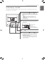
Group Control
1When installing more than 2 units of air
conditioner to one wired remote controller,
please connect as the right figure.
- If it is not event communication indoor
unit, set the unit as slave.
- Check for event communication through
the product manual.
When controlling multiple indoor units with
event communication function with one
remote controller, you must change the
master/slave setting from the indoor unit.
Indoor units, the master/slave
configuration of the product after
completion of indoor unit power ‘OFF’ and
then ‘ON’ the power after 1 minutes
elapsed sign up.
- For ceiling type cassette and duct product
group, change the switch setting of the
indoor PCB.
- For wall-mount type and stand type
product, change the master/slave setting
with the wireless remote controller.
(Refer to wireless remote controller
manual for detail)
* When installing 2 remote controllers to
one indoor unit with event
communication function, set the
master/slave of the remote controller.
(Refer to remote controller master/slave
selection)
When controlling the group, some
functions excluding basic operation setting,
fan level Min/Mid/Max, remote controller
lock setting and time setting may be
limited.
2When installing more than 2 wired remote
controllers to one air conditioner, please
connect as the right picture.
- When installing more than 2 units of
wired remote controller to one air
conditioner, set one wired remote
controller as master and the others all as
slaves, as shown in the right picture.
- You cannot control the group as shown in
the right for some products.
- Refer to the product manual for more
detail.
- When controlling in groups, set the
master/ slaver of the remote controller.
Refer to Installer setting section on how
to set master/slave for more detail.
GND
GND
12 V
Signal wire
Signal
wire
GND
12 V
MASTER SLAVE
Signal wire
GND
12 V
Signal wire
#3 switch OFF: Master
(Factory default setting)
#3 switch ON: Slave

20 INSTALLATION INSTRUCTION
ENGLISH
How to enter the setting mode
CAUTION
The installation setting mode is used for detailed function settings of the wired controller.
The incorrect setting mode may cause product failure or loss of body or property of the user.
The setting must be performed by a person with professional qualification. The company
does not assume responsibility for installation or modification by unprofessional personnel, or
does not provide free repair services.
!
1If wanting to enter manual setting mode,
please press the temperature rise adjustment
key and the operation mode key
simultaneously for 5 seconds.
2When entering the setting mode for the first
time, the function code is displayed at the
bottom of the LCD.
Function Code
<Code Table for Installation Settings>
Value
1) Conventional air-conditioning products
* The display may be different due to different product functions.
Code Function Code Value
1 Trial run 01 01: Settings
2 Address settings 02 00~FF: Address
3 E.S.P settings 03
<Setting> <Setting value> <Example>
01: Ultra low 0~255
02: Low
03: Medium
04: High
05: Ultra high
4 Temperature sensor 04
01: Wired controller sense
02: Indoor unit sense
03: Double sense
5 Ceiling height 05 01: Low 02: Standard
03: High 04: Ultra high
6 Static pressure settings 06
01: Variable / high static pressure
02: Fixed / high static pressure
03: Variable / low static pressure
04: Fixed / low static pressure
7 Main board settings 07 00: Slave 01: Master
8 Celsius / Fahrenheit 12 00: Centigrade
01: Fahrenheit (This feature is only available in the US)
9 Celsius settings 17 00: 1 °C 01: 0.5 °C
10 The detector for
refrigerant leak 29 00: Not Installed
01: Installation
11 Settings for static
pressure setting 32 00: Use static pressure value set in setup mode 06
01~11: Use static pressure value set in setup mode 32
Function
Code
Static pressure
value settings
Static pressure
value
Page is loading ...
Page is loading ...
Page is loading ...
Page is loading ...
Page is loading ...
Page is loading ...
Page is loading ...
Page is loading ...
Page is loading ...
Page is loading ...
Page is loading ...
Page is loading ...
Page is loading ...
Page is loading ...
Page is loading ...
Page is loading ...
Page is loading ...
Page is loading ...
Page is loading ...
Page is loading ...
Page is loading ...
Page is loading ...
Page is loading ...
Page is loading ...
Page is loading ...
Page is loading ...
Page is loading ...
Page is loading ...
-
 1
1
-
 2
2
-
 3
3
-
 4
4
-
 5
5
-
 6
6
-
 7
7
-
 8
8
-
 9
9
-
 10
10
-
 11
11
-
 12
12
-
 13
13
-
 14
14
-
 15
15
-
 16
16
-
 17
17
-
 18
18
-
 19
19
-
 20
20
-
 21
21
-
 22
22
-
 23
23
-
 24
24
-
 25
25
-
 26
26
-
 27
27
-
 28
28
-
 29
29
-
 30
30
-
 31
31
-
 32
32
-
 33
33
-
 34
34
-
 35
35
-
 36
36
-
 37
37
-
 38
38
-
 39
39
-
 40
40
-
 41
41
-
 42
42
-
 43
43
-
 44
44
-
 45
45
-
 46
46
-
 47
47
-
 48
48


LG ABNW30GM1E4 Installation guide
- Category
- Split-system air conditioners
- Type
- Installation guide
Ask a question and I''ll find the answer in the document
Finding information in a document is now easier with AI