Vixen Horns Vxo8210 1 Gallon Air Tank Operating instructions
- Category
- Air compressors
- Type
- Operating instructions

VXO8210/1101
INSTALLATION GUIDE
PAGE 1 of 5
BEFORE BEGINNING YOUR INSTALLATION
Read through the instruction guide before getting started with the installation. Professional installation is recommended for
this product.
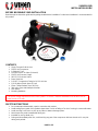
CONTENTS
Single Trumpet Snail Air Horn
150 PSI Air Compressor
1 Gallon Air Tank
12V/24V Electric Air Valve (Solenoid)
150 PSI Air Pressure Gauge
90-115 PSI Pressure Switch
Brass Drain Nut
1/4" NPT Compression Fitting for 1/4" OD Air Line
1/4" OD Nylon Plastic Hose (6 Feet)
12mm Thread Sealant Tape (16 Feet)
30A In-line Fuse with Waterproof Holder
Horn Button
Mounting Hardware
SAFETY INSTRUCTIONS
Do not attempt to disassemble, repair or customize this product.
Avoid setting up any parts of this product where there is a risk of falling off or risk of coming in contact with water.
Avoid reaching out to touch or pick up any fallen or water submerged parts.
Never leave this product unattended during use.
Intended for use by adults only.
During and immediately after use, avoid touching any part of the compressor with bare hands as it is very hot
during such periods.
The specific voltage requirement for this horn system is 12 volt DC, therefore installation must be done to a DC
power source of 12 volts.

VXO8210/1101
INSTALLATION GUIDE
PAGE 2 of 5
Avoid sounding the air horn when in close range to your ear(s) or the ear(s) of others.
Avoid use of product near flames, explosive materials, aerosol products or oxygen devices.
Be sure to pump nothing other than atmospheric air.
It is important to determine the maximum air pressure for any tool or attachment before using it.
Air sprayer or nozzle should always be pointed away from any part of the body.
The compressor has Thermal Overload Protection, if this protection activates, cut off the source of power and let
the unit cool down for about 30 minutes. This will reset the system and allow you to safely resume use of the air
compressor.
Make sure your battery ground is detached before you begin.
Set the horn up for use only in areas with adequate ventilation.
Employ equipment for eye protection during drilling operations.
Ensure that your air system has no pressure before you begin.
PLANNING YOUR INSTALLATION
Before beginning the installation, determine each component’s spot.
Confirm you have the proper length of airline and wire.
Power wire to on-board air system should be kept short.
To power up the on-board air system, make sure you use a 12-gauge wire or thicker.
HORN
MOUNTING
Identify a suitable area for mounting, preferably protected from road debris and spray from the tires. Do not
attach the horn to any plastic or other flexible material.
Using the bracket as a guide estimate and mark the positions for the holes and then perforate to size using a
drill.
Use the provided mounting hardware to fasten the horn.
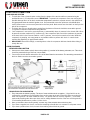
AIR LINE INSTALLATION
On one side of the included ¼” OD air line,
attach the compression nut and force the air
line upon the male inlet fitting which is found on
the electric solenoid valve.
Pass the brass nut through the inlet fitting and
fasten.
Take the air line’s other side and place the
compression nut of the air tank fitting on it.
Force the air line onto the male fitting of the
tank and then fasten the compression nut.
WARNING: Avoid tying the brass nut too tight.
IMPORTANT: The compression fitting may
come without thread sealant applied to his
thread, if that is the case, remove it from the
horn, apply the provided thread sealant to his
threads and tighten to ensure proper air sealing.

VXO8210/1101
INSTALLATION GUIDE
PAGE 3 of 5
ON-BOARD AIR SYSTEM
MOUNTING
Determine a dry place to mount your on-board air system. If you have chosen to install in the engine
compartment, you should mount it as close to the front as possible to allow for maximum flow of air around
compressor and also to avoid heat from the exhaust. IMPORTANT: Never attach the system to any plastic or
other flexible material.
For optimal results, the compressor should be placed as close to the battery as possible. This will reduce the
amount of wiring needed.
Avoid placing compressor near flammable liquids.
For proper heat dissipation of the compressor never install the on-board air system upside down.
Mark the spots for the holes with the mounting base as a guide and then drill. Make sure the system is
secured.
THERMAL OVERLOAD PROTECTION
The compressor has Thermal Overload Protection, if this protection activates, cut off the source of power and
let the unit cool down for about 30 minutes. This will reset the system and allow you to safely resume use of
the air compressor.
PRESSURE SWITCH RATING
The included pressure switch has a rating of 90 PSI ON, 115 PSI OFF. When the air pressure in the air tank
is below the preset ON pressure (90 PSI), the compressor will automatically turn on and will start pumping air
into the tank. When the pressure reaches the cut OFF pressure (115 PSI), the compressor will be
automatically shut off.
In this system your Pressure Switch is already wired to the air compressor. Do not modify this connection.
AIR PRESSURE GAUGE
Your system includes a 150 PSI Pressure Gauge that will measure the air pressure of the tank.
The air pressure gauge is a sensitive part of the system, please avoid dropping, hitting or tighten it to the tank
using a method other than the brass nut located in the back.
DRAIN NUT
This nut helps you drain the water that can collect in the air tank after long periods of use.
REMOVING CONDENSATION:
To remove any condensation which has accumulated inside the tank, bleed the tank’s pressure until it ranges
from approximately 5 PSI to 20 PSI.
Remove the drain nut found at the tank’s bottom to drain the water from the tank. After draining the
accumulated condensation, apply thread sealant to the nut’s thread and reinstall it.
IMPORTANT: Draining the system regularly will extend the life of the air tank.
MAINTENANCE
Make sure that electrical and fitting connections are regularly inspected, cleaned and tightened when needed.
Make sure mounting screws are regularly tightened if needed.
Drain weekly, to avoid excessive buildup of condensation.
Compressor features a washable air filter which should be cleaned using any mild form of liquid soap every
two months if it gets dusty. Just remove the front cover of the filter’s housing to reach it. Replacement time
frames depend on the operating environment and how often it is used.
Clean dirt and dust from heat spreader and motor housing of the compressor.
The motor of the air compressor has a maintenance-free lasting lubricant. DO NOT LUBRICATE.

VXO8210/1101
INSTALLATION GUIDE
PAGE 4 of 5
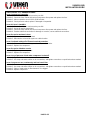
ELECTRICAL CONNECTION
ON-BOARD AIR SYSTEM
The red wire of the on-board system coming from the bottom of the tank should be connected using the
provided fuse to (+) 12-volt power source. IMPORTANT: To prevent the compressor from over running and
possible damage due to an air leak, connect the compressor’s red wire to a power source in the vehicle that
only gets power when the vehicle’s ignition is on. Recommended connection points are: windshield wiper
motor, blower motor or an accessory terminal on the fuse panel. Make sure to use wire that is as heavy as the
wire of the compressor.
The black wire of the on-board system coming from the bottom of the tank should be connected to ground.
The ground connection should be rust and paint free.
Your compressor is now set for use and will turn on automatically when air pressure in the air tank falls. When
air pressure reaches maximum PSI, it will turn off. If the compressor fails to reach the maximum air pressure
of the tank, which is the Pressure Switch's cut OFF pressure, check all air connections for leaks. While the
compressor is pumping, use soapy water or any bubble solution to perform this check. In case the leak
remains after tightening, re-apply thread sealant.
IMPORTANT: Never touch fittings, connecting tubes or the air compressor with bare hands either during or
shortly after use.
HORN (SOLENOID)
USING NEW HORN BUTTON
Connect one of the electric valve’s wires to the positive (+) terminal of the battery, alternator, etc. This circuit
should be protected using a 10A fuse (not provided).
Connect the second electric valve wire to one of the Horn Button’s connections. The remaining connection of
the Horn Button must be connected to ground.
USING VEHICLE’S HORN SWITCH
First, determine the switch’s polarity. The horn of most vehicles sends a negative (-) signal which can be
confirmed by connecting one of the probes from an ohm meter to the wire of the horn while connecting the
other one to ground. The meter should be at zero. This proves that horn circuit is negative (-). In case the
meter reads anything other than zero ohms, test for voltage between the wire of the horn and the ground. A
12-volt reading would mean a positive (+) horn circuit.
Once you know the horn circuit’s polarity, connect any of the solenoid wires to the horn wire.
If you have a negative horn circuit, connect the remaining solenoid wire to a constant 12-volt power source.
If you have a positive horn circuit, connect the remaining solenoid wire to ground.

VXO8210/1101
INSTALLATION GUIDE
PAGE 5 of 5
SOLUTIONS TO COMMON ISSUES
Issue: Compressor inoperable.
Solution 1: Check all switches to make sure they are ON.
Solution 2: Check the fuse; if blown, disconnect compressor from power and replace the fuse.
Solution 3: Allow compressor to cool off for 30-60 minutes.
Solution 4: Check pressure switch, replace if damaged or inoperable.
Issue: Air horn is inaudible
Solution 1: Check all switches to make sure they are ON.
Solution 2: Assure air tank is pressurized.
Solution 3: Check the fuse; if blown, disconnect compressor from power and replace the fuse.
Solution 4: Examine electrical connection for damage or corrosion, secure electrical connections.
Issue: Excessive moisture in horn.
Solution 1: Depressurize and drain the tank.
Solution 2: Relocate the on-board air system to a drier location.
Issue: Continual cutting-off of Thermal overload protection.
Solution 1: Relocate the on-board air system to a drier, cooler location.
Solution 2: Replace the compressor.
Issue: Excessive vibration or noise
Solution 1: Tighten system components.
Solution 2: Replace the compressor.
Issue: Loss of pressure of tank when compressor is shut off.
Solution 1: Tighten drain cock.
Solution 2: Use soap and water solution on air connections, and tighten connections or repair leaks where needed.
Issue: Compressor runs continuously and has low air flow.
Solution 1: Decrease the frequency of use.
Solution 2: Use soap and water solution on air connections, and tighten connections or repair leaks where needed.
Solution 3: Clean or replace the air filter element if it is clogged.
Solution 4: Replace compressor.
-
 1
1
-
 2
2
-
 3
3
-
 4
4
-
 5
5


Vixen Horns Vxo8210 1 Gallon Air Tank Operating instructions
- Category
- Air compressors
- Type
- Operating instructions
Ask a question and I''ll find the answer in the document
Finding information in a document is now easier with AI