Unauthorized reproduction or copying of all or part of this manual is prohibited.
Characteristics, specications and dimensions are subject to change without notice.
is a registered trademark or trademark of Oriental Motor Co., Ltd., in Japan and other
countries.
© Copyright ORIENTAL MOTOR CO., LTD. 2006
Published in September 2019
2
echnical Support Tel:(800)468-3982
A.M. to 5:00 P.M., P.S.T. (M-F)
A.M. to 5:00 P.M., C.S.T. (M-F)
.orientalmotor.com
Schiessstraße 44, 40549 Düsseldor
f, Germany
echnical Support Tel:00 800/22 55 66 22
.orientalmotor.de
el:01256-347090
.oriental-motor.co.uk
el:01 47 86 97 50
.orientalmotor.fr
el:02-93906346
el:+55-11-3266-6018
.orientalmotor.com.br
• Please contact your nearest Oriental Motor oce for further information.
Singapore
Tel:1800-8420280
www.orientalmotor.com.sg
Tel:1800-806161
www.orientalmotor.com.my
Tel:1800-888-881
www.orientalmotor.co.th
Tel:400-820-6516
www.orientalmotor.com.cn
Tel:+91-80-41125586
www.orientalmotor.co.in
Hong Kong Branch
Tel:+852-2427-9800
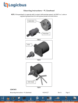
Attaching the load
Refer to following table for hollow shaft inside dimensions and the recommended load
shaft dimensions. Attach the load according to load shaft conditions as shown in the
following gures. The hollow shaft inside dimension is processed to a tolerance of H8, and
incorporates a key slot for load shaft attachment.
A load shaft tolerance of h7 is recommended. Apply a lubricant such as molybdenum
disulphide grease etc. to the load shaft and to the inner circumference of the hollow shaft.
Attach the safety cover provided for protection form the gearhead shaft rotation. Use a
tightening torque of 0.35 to 0.45 N·m (3.0 to 3.9 lb-in).
Note
Do not apply excessive force when inserting the load shaft into the
gearhead. Excessive or abrupt force may damage the gearhead internal
bearings.
The output shaft cannot be rotated manually for models 5GU120RH
to 5GU180RH, 5GE120RH to 5GE180RH. Use the motor for position
adjustment and alignment to equipment.
Be sure to secure the parallel key to the load shaft when inserted into the
hollow shaft.
Hollow shaft Inside dimensions and recommended load shaft dimensions
[Unit: mm (in.)]
Model 4GNRH, 5GNRH 5GURH, 5GERH
Hollow shaft inside
dimensions (H8) Ø15
(Ø0.5906
) Ø17
(Ø0.6693
)
Recommended load shaft
dimensions (h7) Ø15
(Ø0.5906
) Ø17
(Ø0.6693
)
The square box in the gearhead model will contain a value representing the gear ratio.
When the load shaft is stepped
Spacer
Flat washer
Spring washer
Groove for
Screw
When the load shaft is not stepped
Spacer
Spacer
Flat washer
Spring washer
Groove for
retaining ring
Screw
Safety cover attachment
Safety cover (provided)
screws (M3) (provided)
Precautions for use
Use in a location having an ambient operating temperature range between 0 to +50 °C
(+32 to +122 °F) and humidity below 85%.
Avoid locations exposed to direct sunlight, water, or oil.
Avoid locations with vibration or heavy shocks, locations with excessive dust, and
locations with explosive or corrosive gas.
On rare occasions, grease may ooze out from the gearhead. If there is concern over
possible environmental damage resulting from the leakage of grease, check for grease
stains during regular inspections. Alternatively, install an oil pan or other device to
prevent leakage from causing further damage. Grease leakage may lead to problems in
the customer’s equipment or products.
If the ambient temperature is low, the motor may take a longer time to start or its speed
may drop. This is caused, among others, by an increased friction torque of the oil seal
used on the gearhead output shaft. As the motor continues to operate and the sliding
part of the oil seal breaks in, the friction torque will drop and the motor will operate at
the specied speed.
Direction of rotation of the gearhead output shaft
The motor and gearhead output shaft rotate in opposite directions.
Maximum permissible torque
The maximum permissible torque is dened by the size and the gear ratio of the
gearhead. Use within the range of the permissible torque in accordance with each gear
ratio. Also, be sure shaft rotation is not stopped by an external force or load obstruction.
The resulting shock may damage the gearhead.
Permissible radial load and permissible axial load
The radial load and axial load have a great inuence
on the life of the bearings and strength of the shaft.
Do not exceed the permissible radial load and
permissible axial load. Refer to catalogue for details. Load shaft
Axial load


