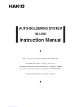
Hako 951/952 User manual

Type
User manual

This manual is also suitable for

®
Instruction Manual
Thank you for purchasing the Hakko 951/952 soldering gun.
This soldering gun has a built-in feeding mechanism that enables soldering with one hand.
Please read this manual before operating the Hakko 951/952.
Keep this manual readily accessible for reference.
CAUTION
When using this unit for the first time, be sure to calibrate the tip temperature. Specific
information can be found in the instruction manual for your particular Hakko station.
When inserting solder, be sure to push up the trigger and insert the solder until the end of
the solder protrudes from the guide nozzle.
Packing List
Soldering gun
Applicable Models
In order to function, the Hakko 951/952 must be connected to one of
the following Hakko stations: Hakko 700, 701, 702, 702B, 926, 927,
928, 936, 937.
Specifications
Name
Power consumption
Temperature range
Tip to ground
resistance
Tip to ground potential
Heating Element
Standard tip
Standard guide nozzle
(Solder diameter)
Usable solder diameter
Cord assembly
Total length (w/o cord)
H W D
Weight (w/o cord)
Hakko 951
AC 24 V 50 W
200 C480 C/392 F896 F
Under 2
Under 2 mV(TYP. 0.6 mV)
Ceramic heater
Shape-3C
Pre-tinned surface 55
(No.900M-T-S10)
ø1.0 mm (0.039 in.)
ø0.6, 0.8, 1.0, 1.2 1.6 mm
(ø0.024, 0.031, 0.039, 0.047, 0.063 in.)
1.1 m (3.6 ft.)
180 170 23 mm (7.1 6.7 0.9 in.)
177 g (0.39 lbs.)
Hakko 952
Shape-B
(No.900L-T-B)
187 g (0.41 lbs.)
*Specifications and design are subject to change without notice.
Precautions
WARNING
Warnings and cautions are placed at critical points in this manual
to direct the operators attention to significant items. They are
defined as follows:
WARNING: Failure to comply with a WARNING may result in serious
injury or death.
CAUTION: Failure to comply with a CAUTION may result in injury
to the operator, or damage to the items involved. Two
examples are given below.
CAUTION
When power is ON, tip temperatures will be between 200 C and
480 C. (392 F to 896 F.) To avoid injury or damage to personnel
and items in the work area, observe the following:
Do not touch the tip or the metal parts near the tip.
Do not allow the tip to come close to, or touch, flammable materials.
Inform others in the area that the unit is hot and should not be
touched.
Turn the power off when not in use, or left unattended.
Turn the power off and allow the unit to cool to room temperature
when changing parts or storing the Hakko 951/952.
CAUTION
To prevent accidents or damage to the Hakko 951/952, be sure to
observe the following:
Do not use the unit for applications other than those specifically
described in the instruction manual.
Before using the Hakko 951/952 for the first time, calibrate the tip
temperature.
Do not strike the gun against hard objects to remove excess solder.
This will damage the gun.
Do not modify the Hakko 951/952.
Use only genuine Hakko replacement parts.
Do not allow the Hakko 951/952 to become wet, or use it when hands
are wet.
Be sure the work area is well ventilated. Soldering produces smoke.
Remove power and gun cords by holding the plug not the wires.
1
Troubleshooting guide
For details, refer to the instruction manual for the station with which the
unit will be used.
The solder clogs.
ACTION
: Do not pull solder from a heavy reel with the trigger. Keep the
solder loose (without tension) on the solder inlet side at all
times while soldering.
ACTION
: Refer to “Inserting the solder” under Operation.
Checking for breakage of the heating
element and cord assembly
Disconnect the plug and measure the resistance between the
connecting plug pins as follows.
3
1
24
5
a. Between pins 4 & 5
(Heating element)
b. Between pins 1 & 2
(Sensor)
c. Between pin 3 & tip
2.5 3.5 (Normal)
43 58 (Normal)
under 2
If the values of a and b are outside the above value, replace the heating
element (sensor) and /or cord assembly.
If the value c is over the above value, remove the oxidization film by
lightly rubbing with sand-paper or steel wool the points shown below.
Rub lightly
Broken heating element
Disassembling the 951/952
1. Remove the adjusting screw and keep the support fitting apart
from the housing.
2. Turn the nut counterclockwise and remove the tip enclosure ,
the tip .
CAUTION
Be sure to remove the nut before removing the nipple. Removing the nipple
first could cause the heater leads to twist and cause a short circuit.
3. Turn the nipple counterclockwise and remove it from the gun.
4. Remove the 4 screw securing the housing and open the housing.
5. Pull the grounding spring out of the sleeve.
1
2
Nut
Tip enclosure
3Tip
4
5
Nipple
Grounding
spring
2
Part Name
Solder inlet
Tip
Guide nozzle
Cord assembly
Support fitting
Adjusting screw
Trigger
Plug
Solder feed
adjusting screw
Operation
Inserting the solder
Push and hold the trigger upward in the direction of the arrow and
pass solder through the solder inlet until it protrudes from the guide
nozzle.
CAUTION
The solder may become stuck inside the unit if the trigger is pulled before the
solder protrudes from the guide nozzle.
Feeding the solder
Return the trigger to its original position after inserting the solder.
Solder can now be fed by pulling the trigger.
CAUTION
Keep the solder loose (without tension) on the solder inlet side at all times while
soldering.
Adjusting the guide nozzle
Adjust the position where the solder touches the tip by loosening the
adjusting screw and moving the guide nozzle up or down.
Solder feed adjustment
Adjust the solder feed pitch by turning the solder feed adjusting screw
with a screwdriver.
The feed pitch decreases as the screw is tightened.
(Range: minimum of 2 mm (0.079 inch) to maximum of 8 mm
(0.315 inch))
Changing to a different solder diameter
To change to a different diameter of solder, push and hold the trigger
upward in the direction of the arrow and pull the current solder out of
the unit via the solder inlet. Then insert the new solder as described
under Inserting solder above.
Connections
1. Make sure the station power switch is OFF and connect the plug to
the receptacle of the station.
2. Place the Hakko 951 or 952 on the iron holder (optional).
3. Plug the power cord into a grounded wall socket.
Be sure the unit is grounded.
Calibration
Be sure to calibrate the tip temperature before using it. (Refer to the
instruction manual for the station.)
* Use a Hakko 191 Thermometer or a Hakko 192 Soldering Tester to measure
the tip temperature.
* Measure when the heating element is at room temperature.
Resistance value of heating
element (RED)
Resistance value of sensor
(BLUE)
2.5 – 3.5
43 58
Resistance value
of heating element
Resistance value
of sensor
If the resistance value is not normal, replace the heating
element.
(Refer to the instructions included with the replacement part.)
After replacing the heating element,
1. Measure the resistance value between pins 4 & 1 and 4 & 2, and
pins 5 & 1 and 5 & 2. If the resistance value is not infinite for all four
measurements, the heating element and sensor leads are
touching. This will damage the P.W.B. When reassembling, be
sure that the heating element and sensor leads do not touch.
2. Measure the resistance value a b c to confirm that the leads are
not twisted and that the grounding spring is properly connected.
CAUTION
When reassembling, match the
convex part of the hexagon nut to
concave part of the housing.
Broken soldering gun cord
There are two methods of testing the soldering gun cord.
CAUTION
The LED heater lamp will flicker even with a normal gun cord if the temperature
reaches 480 C (896 F).
1. Turn the unit on and set the temperature to 480 C (896 F). Then
wiggle and kink the gun cord at various locations along its length,
including strain relief area. If the LED heater lamp flickers, then the
cord needs to be replaced.
2. Check the resistance value between the pin of the plug and the
wire on the terminal.
Pin 1: Red Pin 2: Blue Pin 3: Green Pin 4: White Pin 5: Black
The value should be 0 .
If it is greater than 0 or is infinite, the cord should be replaced.
Parts list (Tips)
0 C
3
0.5(0.02)
900M-T-1.6D
0 C
5
0.5(0.02)
900M-T-2.4D
6.5
0.5(0.02)
900M-T-3.2D
0 C
951
900M-T-SB
0 C
900M-T-0.8C
-10 C/-18 F
900M-T-2C/900M-T-2CF*
0 C
900M-T-3C/900M-T-3CF*
0 C
900M-T-S4
0 C
900M-T-S10*
0 C
900M-T-S11*
0 C
951 tip out diam. ø6.5mm
For heavy duty soldering Hakko recommends the 952 gun with heavier tips.
952
900L-T-B
0 C
900L-T-2B
0 C
0 C
900L-T-2.4D
900L-T-3.2D
0 C
-20 C/-36 F
900L-T-2C/900L-T-2CF*
0 C
900L-T-3C/900L-T-3CF*
900L-T-4C/900L-T-4CF*
0 C
900L-T-5C/900L-T-5CF*
0 C
900L-T-K
+20 C/+36 F
CAUTION Use only genuine replacement tips for Hakko 951,952. The tips for Hakko Dash are not available to use. These tips are tinned flat only.
952 tip out diam. ø8.5mm
(0.12)
ø3.2
(0.09)
ø2.4
(0.06)
ø1.6
(0.25)
17(0.66)
17(0.66)
17(0.66)
(0.2)
(0.1)
14(0.55)
R0.2(0.008)
(0.08)
ø2
900M-T-B/900M-T-BF2*
0 C
*BF2 is tinned a distance of 2mm (0.08 in.) from the end of the tip.
17(0.66)
R0.5(0.02)
17(0.66)
(0.031)
ø0.8
45
17(0.66)
(0.08)
ø2
45
17(0.66)
(0.1)
ø3
45
900M-T-4C/900M-T-4CF*
0 C
17(0.66)
(0.16)
ø4
45
15(0.6)
R0.25(0.01)
(0.08)
ø2
17(0.66)
(0.1)
ø3
55
17(0.66)
(0.16)
ø4
55
20(0.79)
R0.5(0.02)
20(0.79)
R1(0.04)
20(0.79)
(0.09)
ø2.4
5(0.2)
0.5(0.02)
20(0.79)
(0.12)
ø3.2
8(0.32)
0.5(0.02)
20(0.79)
(0.08)
ø2
45
20(0.79)
(0.1)
ø3
45
20(0.79)
(0.16)
ø4
45
15(0.6)
(0.2)
ø5
45
18(0.71)
(0.2)
ø5
2(0.08)
45
15(0.6)
900M-T-K
45
+30 C/+54 F
(0.2)
ø5
2(0.08)
The tip temperature will vary according to the shape of the tip. The preferred
method of adjustment uses a tip thermometer. (Refer to the instruction manual
for the station.) A less accurate method involves adjusting the temperature
settings according to the adjustment value for each tips.
Examples: When using a 900M-T-0.8C tip at 400 C (750 F), the
difference between this tip and standard tip is 10 C (18 F).
Set the temperature to 410 C (768 F).
Refer to the chart for the correct adjustment values.
3
Hexagon nut M4
Parts list
Note: Spare or repair parts do not include mounting screws, if they are not
listed on the description. Screws must be ordered separately.
Nov. 2000
MA00973JU001130
1
2
3
4
5
6
7
8
9
10
11
13
14
16
17
19
18
20
15
12
Hexagon nut
M4
Item No.
1
2
3
4
5
6
7
8
9
10
11
12
13
14
15
16
17
18
19
20
Part No.
B2644
B2643
B2032
A1321
B2022
B2033
B1786
B1787
B1784
B1794
B2648
B2646
B2645
B2658
B2657
B1100
B2647
B2659
B1710
B2652
B2653
B2654
B2655
B2656
B2649
B2650
Part Name
Housing
Terminal board
Grounding spring
Heating element
Nipple
Nipple
Soldering tip
Tip enclosure
Tip enclosure
Nut
Nut
Trigger set
Solder feed adjusting screw
guide
Solder feed adjusting screw
Spring for trigger assey
Solder inlet
Cord bushing
Cord asse'y
Guide pipe
Nozzle securing ring
Guide nozzle / 0.6mm ESD
Guide nozzle / 0.8mm ESD
Guide nozzle / 1.0mm ESD
Guide nozzle / 1.2mm ESD
Guide nozzle / 1.6mm ESD
Support fitting
Adjusting screw
Description
With screws, labels
For 951
For 952
See page 3
For 951
For 952
For 951
For 952
With nut
With grommet
For guide pipe
Option
Part No.
C1437
A1042
Part Name
Iron holder
Cleaning sponge
Description
4
OVERSEAS AFFILIATES
U.S.A.: AMERICAN HAKKO PRODUCTS, INC.
25072 ANZA DR. SANTA CLARITA, CA 91355, U.S.A.
TEL: (661) 294-0090 FAX: (661) 294-0096
Toll Free (800)88-HAKKO
4 2 5 5 6
http://www.hakkousa.com
HONG KONG: HAKKO DEVELOPMENT CO., LTD.
ROOM 1504, EASTERN HARBOUR CENTRE,
28 HOI CHAK STREET, QUARRY BAY, HONG KONG.
TEL: 2811-5588 FAX: 2590-0217
http://www.hakko.com.hk/
CHINA: HAKKO DEVELOPMENT CO., LTD.
ROOM 1112-1115, 11 FLOOR, INTERNATIONAL BANK
TOWER 191 DONGFENG ROAD WEST, GUANGZHOU
510180, CHINA.
TEL: (020)8135-0112, 8135-0113 FAX: (020)8135-0181
TAIWAN: HAKKO DEVELOPMENT CO., LTD.
3F., NO 110, CHUNG HSIN RD., SEC.3, SANCHUNG, TAIPEI
HSIEN, TAIWAN.
TEL: (02)2975-2600 FAX: (02)2973-9565
S'PORE: HAKKO PRODUCTS PTE., LTD.
1, GENTING LINK #02-04, PERFECT INDUSTRIAL
BUILDING, SINGAPORE 349518
TEL: 748-2277 FAX: 744-0033
E-mail: sales@hakko.com.sg
MALAYSIA: HAKKO PRODUCTS SDN BHD
MALAYSIA HEAD OFFICE
NO.22,JALAN PEMBERITA U1/49,SEKSYEN U1,
TEMASYA INDUSTRIAL PARK,40150 GLENMARIE,
SHAH ALAM,SELANGOR DARUL EHSAN,WEST MALAYSIA.
TEL: (03)519-5223 FAX: (03)519-5221
PENANG BRANCH: TEL: (04)507-0888 FAX: (04)507-0999
JOHORE BAHRU BRANCH: TEL: (07)236-7766 FAX: (07)237-4655
PHILIPPINES: HAKKO PHILS TRADING CO., INC.
NO. 415 WINDSOR TOWER CONDOMINIUM,
163 LEGASPI ST., LEGASPI VILLAGE MAKATI,
METRO MANILA, PHILIPPINES
TEL: (02)817-0712, 815-4993 FAX: (02)810-7649
E-mail: hakk[email protected]
INDONESIA: P.T. HAKKO PRODUCTSTAMA INDONESIA
COMP BUMI INDAH BLOK IV NO. 40 NAGOYA BATAM, INDONESIA.
TEL: (778)457-459 FAX: (778)452-772
E-mail: hakk[email protected]
P.T. HAKKO PRODUCTSTAMA INDONESIA
KEBON JERUK PLAZA, BLOK D NO. 6, JALAN RAYA PERJUANGAN,
JAKARTA BARAT, JAKARTA 11530, INDONESIA.
TEL: (21)532-4083 FAX: (21)532-4082
E-mail: hakk[email protected]
HEAD OFFICE
4-5, SHIOKUSA 2-CHOME, NANIWA-KU, OSAKA, 556-0024 JAPAN
TEL:+81-6-6561-3225 FAX:+81-6-6561-8466
http://www.hakko.com
®
  • Page 1 1
  • Page 2 2
  • Page 3 3
  • Page 4 4

Hako 951/952 User manual

Type
User manual
This manual is also suitable for

Ask a question and I''ll find the answer in the document

Finding information in a document is now easier with AI