3
Location Requirements
IMPORTANT: Observe all governing codes and ordinances. Do
not obstruct flow of combustion and ventilation air.
■ It is the installer’s responsibility to comply with installation
clearances specified on the model/serial rating plate. The
model/serial rating plate is located on the underside of the
cooktop burner box.
■ To eliminate the risk of burns or fire by reaching over heated
surface units, cabinet storage space located above the
surface units should be avoided. If cabinet storage is to be
provided, the risk can be reduced by installing a range hood
that projects horizontally a minimum of 5" (12.7 cm) beyond
the bottom of the cabinets.
■ All openings in the wall or floor where cooktop is to be
installed must be sealed.
■ Cabinet opening dimensions that are shown must be used.
Given dimensions are minimum clearances.
■ Grounded electrical supply is required. See “Electrical
Requirements” section.
■ Proper gas supply connection must be available. See “Gas
Supply Requirements” section.
■ The cooktop is designed to hang from the countertop by its
side or rear flanges.
■ The gas and electric supply should be located as shown in
“Cabinet Requirements” section so that they are accessible
without requiring removal of the cooktop.
■ Provide cutout in right rear corner of cutout enclosure as
shown to provide clearance for gas inlet and power supply
cord, and to allow the rating label to be visible.
■ Ovens approved for this type of installation will have an
approval label located on the top of the oven. If you do not
find this label, contact your dealer to confirm that your oven is
approved. Refer to oven manufacturer’s Installation
Instructions for approval for built-in undercounter use and
proper cutout dimensions.
IMPORTANT: To avoid damage to your cabinets, check with your
builder or cabinet supplier to make sure that the materials used
will not discolor, delaminate or sustain other damage.
Mobile Home - Additional Installation Requirements
The installation of this cooktop must conform to the
Manufactured Home Construction and Safety Standard, Title 24
CFR, Part 3280 (formerly the Federal Standard for Mobile Home
Construction and Safety, Title 24, HUD Part 280). When such
standard is not applicable, use the Standard for Manufactured
Home Installations, ANSI A225.1/NFPA 501A or with local codes.
In Canada, the installation of this cooktop must conform with the
current standards CAN/CSA-A240-latest edition, or local codes.
Product Dimensions
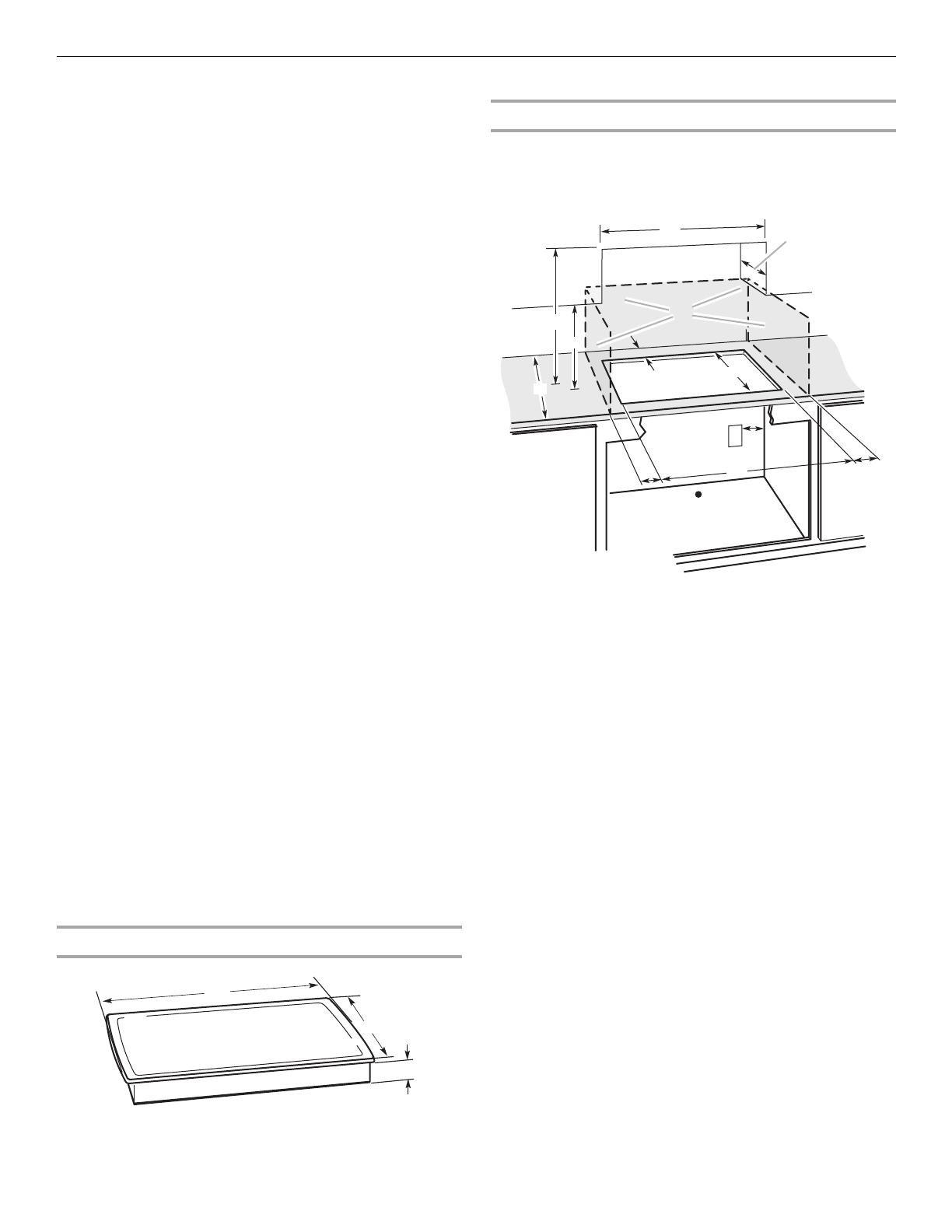
Cabinet Requirements
IMPORTANT: If installing a range hood or microwave hood
combination above the range, follow the range hood or
microwave hood combination installation instructions for
dimensional clearances above the cooktop surface.
NOTES: After making the countertop cutout, some installations
may require notching down the base cabinet side walls to clear
the burner box. To avoid this modification, use a base cabinet
with sidewalls wider than the cutout.
If cabinet has a drawer, a 4" (10.2 cm) depth clearance from the
countertop to the top of the drawer (or other obstruction) in base
cabinet is required. The drawer depth may need to be shortened
to avoid interfering with the regulator.
A. 23
¹⁄₄
" (59.0 cm)
B. 20
⁵⁄₆₄
" (51.0 cm)
C. 1
¹⁄₂
" (3.8 cm)
A
B
C
A. 24" (61 cm) minimum - 26" (68 cm) maximum distance
between overhead cabinets
B. 13" (33 cm) minimum recommended upper cabinet depth
C. 30" (75 cm) minimum combustible area above countertop
(shown by dashed box above)
D. 18
²⁹⁄₃₂
" (48 cm)
E. Grounded outlet - Locate within 24" (61 cm) of right rear
corner of cutout.
F. 2 2
³⁄₆₄
" (56 cm)
G. Gas line opening -
Wall: anywhere 5" (12.7 cm) below underside of countertop.
Cabinet floor: anywhere within 6" (15.2 cm) of rear wall is
recommended.
H. 4" (10 cm) minimum distance to nearest left and right side
combustible surface
I. 2
⁷⁄₈
" (7 cm) minimum distance to rear combustible surface
J. 20
¹⁄₂
" (52 cm) minimum clearance from upper cabinet to
countertop within minimum horizontal clearances to cooktop
K. 29
¹⁄₂
" (75 cm) minimum clearance between top of cooktop
platform and bottom of uncovered wood or metal cabinet
(24" [61 cm] minimum clearance if bottom of wood or metal
cabinet is covered by not less than
¹⁄₄
" [0.6 cm] flame retardant
millboard covered with not less than No. 28 MSG sheet steel,
0.015" [0.04 cm] stainless steel, or 0.024" [0.06 cm] aluminum
or 0.020" [0.05 cm] copper)
L. 25
⁵⁄₈
" (65.09 cm) minimum countertop depth is required.
C
B
A
E
F
H
I
G
K
L
D
J


