Peavey RQ 4300 Series User manual
- Category
- DJ controllers
- Type
- User manual
Page is loading ...

2
Intended to alert the user to the presence of uninsulated “dangerous voltage” within the product’s
enclosure that may be of sufficient magnitude to constitute a risk of electric shock to persons.
Intended to alert the user of the presence of important operating and maintenance (servicing)
instructions in the literature accompanying the product.
CAUTION: Risk of electrical shock — DO NOT OPEN!
CAUTION: To reduce the risk of electric shock, do not remove cover. No user serviceable parts inside. Refer
servicing to qualified service personnel.
WARNING: To prevent electrical shock or fire hazard, do not expose this appliance to rain or moisture. Before
using this appliance, read the operating guide for further warnings.
Este símbolo tiene el propósito, de alertar al usuario de la presencia de “(voltaje) peligroso” sin ais-
lamiento dentro de la caja del producto y que puede tener una magnitud suficiente como para constituir
riesgo de descarga eléctrica.
Este símbolo tiene el propósito de alertar al usario de la presencia de instruccones importantes sobre la
operación y mantenimiento en la información que viene con el producto.
PRECAUCION: Riesgo de descarga eléctrica ¡NO ABRIR!
PRECAUCION: Para disminuír el riesgo de descarga eléctrica, no abra la cubierta. No hay piezas útiles dentro.
Deje todo mantenimiento en manos del personal técnico cualificado.
ADVERTENCIA: Para evitar descargas eléctricas o peligro de incendio, no deje expuesto a la lluvia o humedad
este aparato Antes de usar este aparato, Iea más advertencias en la guía de operación.
Ce symbole est utilisé dans ce manuel pour indiquer à l’utilisateur la présence d’une tension dangereuse
pouvant être d’amplitude suffisante pour constituer un risque de choc électrique.
Ce symbole est utilisé dans ce manuel pour indiquer à l’utilisateur qu’il ou qu’elle trouvera d’importantes
instructions concernant l’utilisation et l’entretien de l’appareil dans le paragraphe signalé.
ATTENTION: Risques de choc électrique — NE PAS OUVRIR!
ATTENTION: Afin de réduire le risque de choc électrique, ne pas enlever le couvercle. Il ne se trouve à l’intérieur
aucune pièce pouvant être reparée par l’utilisateur. Confiez I’entretien et la réparation de l’appareil à un réparateur
Peavey agréé.
AVERTISSEMENT: Afin de prévenir les risques de décharge électrique ou de feu, n’exposez pas cet appareil à la
pluie ou à l’humidité. Avant d’utiliser cet appareil, lisez attentivement les avertissements supplémentaires de ce
manuel.
Dieses Symbol soll den Anwender vor unisolierten gefährlichen Spannungen innerhalb des Gehäuses
warnen, die von Ausreichender Stärke sind, um einen elektrischen Schlag verursachen zu können.
Dieses Symbol soll den Benutzer auf wichtige Instruktionen in der Bedienungsanleitung aufmerksam
machen, die Handhabung und Wartung des Produkts betreffen.
VORSICHT: Risiko — Elektrischer Schlag! Nicht öffnen!
VORSICHT: Um das Risiko eines elektrischen Schlages zu vermeiden, nicht die Abdeckung enfernen. Es befinden
sich keine Teile darin, die vom Anwender repariert werden könnten. Reparaturen nur von qualifiziertem
Fachpersonal durchführen lassen.
ACHTUNG: Um einen elektrischen Schlag oder Feuergefahr zu vermeiden, sollte dieses Gerät nicht dem Regen
oder Feuchtigkeit ausgesetzt werden. Vor Inbetriebnahme unbedingt die Bedienungsanleitung lesen.

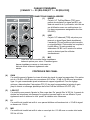
RQ
™
4300 SERIES
Reference Quality Recording and Sound Reinforcement Console
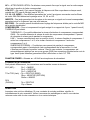
INTRODUCTION
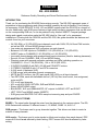
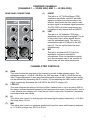
Thank you for purchasing the RQ 4300 Series mixing console. The RQ 4300 represents years of
experience in mixer engineering and offers incredible versatility through its flexible 13-bus design.
Its impressive 4 SUB GROUPS, 6 AUX, L/R and MONO outputs place the RQ 4300 in a league of
its own. Additionally, each SUB group features a high-quality dynamic compressor that can be used
on the corresponding SUB mix, or can be patched to any channel INSERT. Compact package
design and rugged construction make the RQ 4300 ideal for “the road” or for permanent
installations. Covering both the RQ 4324 and the RQ 4332, this guide describes the features and
controls found on your new mixer:
• 24 (RQ 4324) or 32 (RQ 4332) input channels; each with GAIN, EQ, AUX and PAN controls,
as well as SUB, L/R and MONO assign buttons
• Low-noise mic preamps and XLR connectors on each channel
• Balanced 1/4" LINE inputs on CHANNELS 1-22 (RQ 4324) or 1-30 (RQ 4332)
• INSERT jacks on CHANNELS 1-20 (RQ 4324) or 1-28 (RQ 4332)
• Innovative chassis design with recessed back panel connectors (ideal for desktop placement)
• Smooth, 60 mm CHANNEL, SUB, L/R and MONO faders
• Phantom power with separate activation switches and LEDs indicating operation on
CHANNELS 1-16 or 17-24 (RQ 4324); 1-24 or 25-32 (RQ 4332)
• 2 SUPER CHANNELS with PAD (-20 dB) and POLARITY buttons
• 2 STEREO CHANNELS with 1/4" and RCA connectors
• 6 AUX sends (4 balanced XLR)
• 4 SUB groups with patchable dynamic compressors
• MUTE and PFL buttons, clip (PK) and signal (SIG) LEDs on all input channels
• Two RETURNs, each with switchable low-cut (150 Hz) filter, level control, bus assignment,
mute and AFL
• PFL on all input channels
• AFL on all AUX SEND, RETURN, SUB and MONO channels
• Stereo HEADPHONE output
• BALANCED XLR and UNBALANCED 1/4" outputs for MONO, LEFT and RIGHT
• LEFT, RIGHT and MONO master INSERTS
• SUB group and MASTER CLIP LEDs sample at summing amp and post-FADER
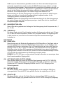
EXPLANATION OF TERMS
BUSES – The signal paths through the mixer from the channels to the various outputs. The RQ
4300 Series mixer contains 13 different buses: L, R, MONO, SUBS 1-4, AUX 1-6.
SUB groups – The buses used to group channels together. This allows one fader to control a
submix of many channels.
AUX sends – The buses used to route signals to effects and monitors from each channel. PRE
means AUX level is not affected by fader setting; POST means AUX level is affected by fader
setting.
3
ENGLISH

PFL – PRE-FADER LISTEN. PFLs send signals to the headphone output and are not affected by
the fader setting.
AFL – AFTER-FADER LISTEN. AFLs send signals to the headphone output and are affected by
fader setting.
LOW CUT – (channel low cut). These adjust the frequency in the channel where the low frequencies
begin to roll off, and are variable by frequency from OFF (inaudible) to 300 Hz.
1/2, 3/4, L/R, MONO – These buttons route the channels to their respective output buses. BAL/PAN
determines 1/2, 3/4 or L/R.
INSERTS – These jacks allow the signal to be taken from and returned to the channel, allowing
outboard equipment to be inserted into the signal chain.
MID FREQ – This control selects the frequency adjusted by the MID control in the EQ
section.
COMPRESSORS – These reduce levels at a ratio of 4 to 1 when the THRESHOLD is reached.
THRESHOLD – This control sets the level at which compression activates.
GAIN – This control sets the output level from the compressor. This is really a
makeup gain, allowing the user to recover gain lost by compression.
LINK – When these buttons are depressed, the input to compressor 1 activates
compressors 1 and 2, and the input to compressor 3 activates compressors 3 and 4.
SUBGROUP/EXTERNAL – This button routes the compressor signal to the compressor
output jack (LED indicates external jack). This jack is wired reverse of an insert jack, allowing
the compressor to be patched with a 1/4" TRS cable.
PHANTOM POWER – Provides +48 Volt power to microphones that need it.
CONNECTOR WIRING
Unless otherwise stated, all input and output jacks are wired as follows:
XLR (MIC) – Pin 1 = GROUND
Pin 2 = POSITIVE
Pin 3 = NEGATIVE
TS and TRS – Tip = POSITIVE (SEND)
Ring = NEGATIVE (RETURN)
Sleeve = GROUND
RCA
(PHONO) – Tip = POSITIVE
Cup = GROUND
UNPACKING
Inspect the console carefully during unpacking. If you find any damage, notify your dealer
immediately. Be sure to save the carton and all packing materials. Should you ever need to ship the
unit back to Peavey Electronics, one of its service centers, or the dealer; use only the original
factory packing.
4

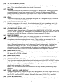
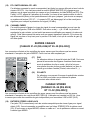
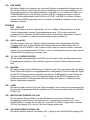
STANDARD CHANNELS
[CHANNELS 1 — 20 (RQ 4324) AND 1 — 28 (RQ 4332)]
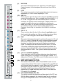
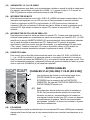
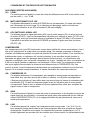
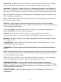
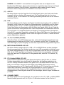
REAR PANEL CONNECTIONS (1) INSERT
This jack is a 1/4" Tip/Ring/Sleeve (TRS)
connection that allows a pre-EQ, pre-fader
signal to be taken from and returned to the
channel. Insert jacks are often used to route
an input signal to an external signal processor.
The RQ 4300’s on-board compressors can
be patched to any channel with an INSERT.
(2) LINE
This jack is a 1/4" balanced (TRS) high
impedance input for high level signals. The tip
is the positive input, which should also be
used for unbalanced inputs. This input is
connected through a 20 dB pad to the MIC
input (3). The two inputs cannot be used
simultaneously.
(3) MIC
This jack is a balanced XLR (3-pin) low-
impedance connection intended for
microphones. Other low-impedance signals
such as instruments sent to the console via
direct boxes will also utilize these inputs.
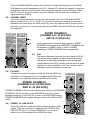
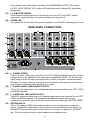
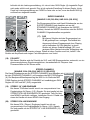
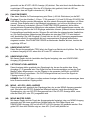
CHANNEL STRIP CONTROLS
(4) GAIN
This control varies the input gain of the channel to provide a wider dynamic range. The
adjustment range is +10 dB to +58 dB for the XLR input and –10 dB to +38 dB for the line
input. Proper adjustment of input gain maximizes signal-to-noise ratio. Optimum gain setting
can be achieved by depressing the PFL switch (15) and adjusting the GAIN control until the
signal occasionally illuminates the 0 dB LED in the AFL/PFL display (45).
(5) LOW CUT
This control adjusts the setting of the low-cut filter. Variable from no cut to cut below 300 Hz,
this feature reduces/eliminates extremely low frequencies that cause “low-end rumble,” and is
a very effective tone shaping tool. It can also be used to reduce the “boominess” sometimes
encountered with male voices.
(6) HI
This active tone control is a shelving-type that varies high-frequency response by +/-15 dB in
the range above 12 kHz.
(7) MID
This active tone control is a bandpass (peak/notch) type that varies mid-frequency response
by +/-15 dB in a range from 200 Hz to 6 kHz.
5
INSERT
MIC
(TRS)
(BAL)
LINE
(BAL)
T
IP=SEND RING=RETURN SLEEVE=GROUND)
INSERT
MIC
(TRS)
(BAL)
LINE
(BAL)
12
3
3
2
1

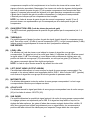
(8) MID FREQ
This control determines the center frequency of the MID control.
Center frequency for the bandpass filter can be set from 200 Hz
to 6 kHz.
(9) LOW
This active tone control is a shelving-type that varies low-frequency
response by +/-15 dB. Corner frequency is 75 Hz.
(10) AUX 1– 4
These controls adjust the level of the channel’s pre-fader signal that
is sent to the auxiliary mix. Gain is variable from minus infinity (– ∞)
to +10 dB. Unity gain is at the center detent position. Pre-fader
auxiliaries are typically used to send signal to stage monitors, but
can also be used to generate an independent recording mix.
NOTE: AUX SENDS 1-4 are factory set to deliver signal pre-EQ, but can
be modified (internally) to deliver signal post-EQ. Contact Peavey
Electronics Service Dept. for information. AUX SENDS 5-6 are always
post-EQ.
(11) AUX 5 – 6
These controls adjust the level of the channel’s post-fader signal
that is sent to the auxiliary mix. Gain is variable from minus infinity
(– ∞) to +10 dB. Unity gain is at the center detent position.
(12) PAN
This control determines the signal’s position with respect to L/R and
SUB 1– 4 outputs. Rotating the control counterclockwise increases
the amount of signal sent to L and odd-numbered SUBs; rotation
clockwise increases the amount sent to R and even-numbered
SUBs. For example, with the channel ASSIGN switch (13) in the
1/2 position, rotating the control counterclockwise increases the
amount of signal sent to SUB 1, while rotating clockwise increases
the amount sent to SUB 2. The C position sends equal amounts
to each.
(13) 1/2, 3/4, L/R, MONO (ASSIGN)
These post-fader, post-EQ switches determine where the channel
signal is being sent. For example, to send a signal to SUBs 1 & 2,
depress the 1/2 button. The PAN control (12) determines how much
signal is sent to each SUB group.
(14) MUTE SWITCH/MUTE-CLIP LED
This switch mutes all AUX, SUB, L/R and MONO sends from the
corresponding channel. This switch is equipped with a red LED that
will illuminate when the channel is muted. When the MUTE switch is
disengaged, the LED functions as a clip (PK) indicator that will
illuminate at 2 dB below clipping. Muting the channel does not
prevent the PFL signal from being sent to the PFL mix when the
PFL switch (15) is engaged.
(15) PFL SWITCH/SIGNAL-PFL LED
This switch connects the channel’s pre-fader signal to the PFL mix.
With this feature engaged, the channel’s signal can be monitored
through the headphones and/or on the AFL/PFL display. A yellow
6
PAN
AUX
1
AUX
2
AUX
3
AUX
4
1
SIG/
PFL
MUTE/
PK
1
dB
10
0
5
3
3
40
15
6
dB
10
0
5
3
3
40
15
6
dB
10
0
5
3
3
40
15
6
dB
10
0
5
3
3
40
15
6
9
5
010
1
8
2
37
64
R
L
C
HI
GAIN
(dB)
CHANNEL
1/2 3/4
L/R MONO
PREPOST
EQUALIZATION
AUX
5
dB
10
0
5
3
3
40
15
6
AUX
6
dB
10
0
5
3
3
40
15
6
LOW
(dB)
12
0
1515
12
9
9
66
33
12
0
1515
12
9
9
66
33
10
6
3
0
6
12
30
20
300
150
20
10050
OFF
LOW
CUT
(Hz)
MID
(dB)
12
0
1515
12
9
9
66
33
MID
FREQ.
(Hz)
6K
2.5K
300
1K700
200
4
5
6
7
8
9
12
16
10
11
13
14
15

LED in the MONO MASTER section (45) will blink to indicate that the signal on the MONO
LED display and at the headphone out is PFL. Selecting PFL allows the operator to monitor a
channel even with the channel muted, and is especially useful for cueing CDs/tapes. When
the PFL button is in the out position, the yellow channel LED will blink as an indication of
signal presence (-20 dBu).
(16) CHANNEL FADER
This control varies the signal level sent from the channel to the L/R, SUB, and/or MONO
master channels from (– ∞) to +10 dB. The 0 position is unity gain, meaning no increase or
decrease in the level set by the GAIN control (4), and is the optimum setting for this control. If
the level is too quiet or too loud at unity gain on the FADER, the channel GAIN (4) may need
to be adjusted.
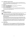
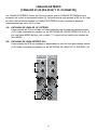
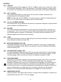
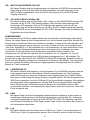
SUPER CHANNELS
[CHANNELS 21–22 (RQ 4324)
AND 29–30 (RQ 4332)]
Input connections and channel strip controls on SUPER
CHANNELS are the same as STANDARD CHANNELS with
the exception of INSERT jacks. In place of INSERT
connections, SUPER CHANNELS are equipped with:
(17) PAD
This switch attenuates (reduces) the input signal by 20 dB.
This allows accommodation of higher input levels without
clipping and is especially useful when close-miking high
sound pressure level (SPL) sources such as drums or guitar
cabinets. It is also beneficial for “hot” line sources such as
keyboards and some wireless microphones.
(18) POLARITY
This switch reverses the polarity of both the XLR and LINE input
connectors to compensate for an out-of-phase signal that would
otherwise cause frequency (phase) cancellations in the mix.
STEREO CHANNELS
[CHANNELS 23–24 (RQ 4324)
AND 31–32 (RQ 4332)]
STEREO CHANNELS offer the same channel strip controls as STANDARD
CHANNELS with the exception of the MID FREQ control (8). Center
bandpass frequency is set at 850 Hz. In place of the MID FREQ control,
STEREO CHANNELS offer independent gain controls for LINE and MIC
(XLR).
(19) STEREO 1/4" LINE INPUTS
These TS jacks are unbalanced line-level inputs for stereo (L/R)
signals. They are connected in parallel with the STEREO RCA
LINE INPUTS (20). If you have a MONO line source, use a Y
cable or one of the channels with a MONO line input.
7
POLARITY
MIC
(BAL)
LINE
(BAL)
MIC
LINE
(BAL)
MIC
(BAL)
REVERSED
NORMAL
0 dB
-20 dB
PAD
POLARITY
REVERSED
NORMAL
0 dB
-20 dB
PAD
21
22
17
18
LEFT
RIGHT
LEFT
RIGHT
MIC
(BAL)
MIC
(BAL)
23s
24s
LEFT
INPUT
RIGHT
INPUT
LEFT
INPUT
RIGHT
INPUT
19
20

(20) STEREO RCA LINE INPUTS
These RCA (phono) inputs are unbalanced line-level inputs for stereo (L/R) signals. They are
connected in parallel with the STEREO 1/4" LINE INPUTS (19).
8
10
6
12
2
4
8
0
10
6
12
2
4
8
0
10
6
12
2
4
8
0
DYNAMICS
MONO
AUX
1
AUX
2
LEVEL
LR
CLIP
0
BAL/
PAN
33
27
21
15
9
6
3
3
6
9
AUX
1
AUX
2
LEVEL
BAL/
PAN
LR
MASTER
10
6
3
0
6
12
30
20
1
AFL
MUTE
RIGHT
MONO
LEFT
CLIP
+6
0
-20
SUB 1
2
AFL
MUTE
RIGHT
MONO
LEFT
CLIP
+6
0
-20
SUB 2
3
AFL
MUTE
RIGHT
MONO
LEFT
CLIP
+6
0
-20
SUB 3
4
AFL
MUTE
RIGHT
MONO
LEFT
CLIP
+6
0
-20
SUB 4
10
6
3
0
6
12
20
30
AFL
CLIP
0
33
27
21
15
9
6
3
3
6
9
CLIP
0
33
27
21
15
9
6
3
3
6
9
CLIP
0
33
27
21
15
9
6
3
3
6
9
MONO
AFL/PFL ACTIVE
RETURN
1
RETURN
2
1/2 3/4
L/R
MONO
1/2 3/4
L/R MONO
HEADPHONE LEVEL
LOW CUT LOW CUT
HEADPHONE
(150 Hz) (150 Hz)
TM
POWER
(+48V)
1-16
17-24
PHANTOM
POWER
MUTE/
PEAK
MUTE/
PEAK
SIG/
AFL
THRESHOLD
(dB)
0 dBu (INPUT)
GAIN
(dB)
LINK 1/2
THRESHOLD
(dB)
0 dBu (INPUT)
GAIN
(dB)
THRESHOLD
(dB)
0 dBu (INPUT)
GAIN
(dB)
THRESHOLD
(dB)
0 dBu (INPUT)
GAIN
(dB)
LINK 3/4
COMP 1 COMP 2 COMP 3 COMP 4
12
9
6
3
1
12
9
6
3
1
12
9
6
3
1
12
9
6
3
1
GAIN
REDUCTION
GAIN
REDUCTION
GAIN
REDUCTION
GAIN
REDUCTION
COMPRESSOR I/O
SUBGROUP
EXTERNAL
COMPRESSOR I/O
SUBGROUP
EXTERNAL
COMPRESSOR I/O
SUBGROUP
EXTERNAL
COMPRESSOR I/O
SUBGROUP
EXTERNAL
AUX
SEND 3
LEVEL
dB
10
0
5
3
3
40
15
6
AUX
SEND 2
LEVEL
dB
10
0
5
3
3
40
15
6
AUX
SEND 1
LEVEL
dB
10
0
5
3
3
40
15
6
AUX
SEND 6
LEVEL
dB
10
0
5
3
3
40
15
6
AUX
SEND 5
LEVEL
dB
10
0
5
3
3
40
15
6
AUX
SEND 4
LEVEL
10
6
3
0
6
12
30
20
10
6
3
0
6
12
30
20
10
6
3
0
6
12
30
20
10
6
3
0
6
12
30
20
10
6
3
0
6
12
20
30
dB
10
0
5
3
3
40
15
6
dB
10
0
5
3
3
40
15
6
dB
10
0
5
3
3
40
15
6
C
dB
10
0
5
3
3
40
15
6
dB
10
0
5
3
3
40
15
6
dB
10
0
5
3
3
40
15
6
9
5
010
1
8
2
37
64
SIG/
AFL
dB
10
0
5
3
3
40
15
6
-30 OFF
-5
-25 +15
-15 +5
-30 OFF
-5
-25 +15
-15 +5
-30 OFF
-5
-25 +15
-15 +5
-30 OFF
-5
-25 +15
-15 +5
R
L
R
L
C
MUTE/
PEAK
MUTE/
PEAK
MUTE/
PEAK
MUTE/
PEAK
MUTE/
PEAK
MUTE/
PEAK
SIG/
AFL
SIG/
AFL
SIG/
AFL
SIG/
AFL
SIG/
AFL
SIG/
AFL
10
6
12
2
4
8
0
10
6
3
0
6
12
30
20
AUXILIARY MASTER
DESIGNED IN U.S.A.
DYNAMICS
21
22
23
24
25
26
27
28
31
33
32
29
30
34
37
39
42
43
38
40
35
41
36
44
47
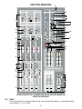
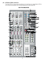
MASTER SECTION
45
48
46

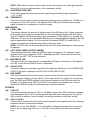
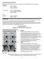
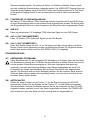
MASTER SECTION FEATURES AND CONTROLS
AUX SENDS
(21) LEVEL
This control sets the output level of the various AUX mixes and is adjustable from no output
(– ∞) to +10 dB.
(22) MUTE SWITCH/MUTE-CLIP LED
This switch mutes the output signal from the respective AUX SEND. Illumination of the
corresponding red LED signifies this status. When the MUTE switch is disengaged, the LED
functions as a clip (PK) indicator that will illuminate at 2 dB below clipping.
(23) AFL SWITCH/AFL-SIGNAL LED
This switch directs the post-fader (AFL) signal to the HEADPHONE output (39), and activates
the AFL/PFL LED display. An adjacent LED illuminates to signify this selection. If AFL is
not selected, the LED will blink as an indication of signal presence (-20 dBu). Selecting AFL
allows monitoring of AUX SENDS with the full AFL/PFL LEVEL DISPLAY (45), as well as
allowing the operator to hear the output.
COMPRESSORS
The compressors on the RQ Series function similarly to automatic volume controls. In other words,
they put signals into a more controllable dynamic range. For example, suppose a singer sings too
softly and gets buried in the mix on certain parts of a song, yet sings really loudly on other parts. To
control this problem, the operator must “ride gain” (turn the volume up and down to achieve a
constant level), but these dynamic changes may be hard to anticipate. Using a compressor
eliminates this problem. The RQ’s compressors are factory set at a ratio of 4 to 1, meaning that for
every 4 dB of change in input signal, the output changes 1 dB. Compression takes place once the
level determined by the THRESHOLD (28) is reached. A high setting, rotating the control clockwise,
will result in only the louder notes being compressed; a low setting, rotating the control
counterclockwise, will compress a broader range of notes.
(24) COMPRESSOR I/O
This switch determines if the compressor will be used on the SUB mix or will be patched to
another channel or other external location. The corresponding yellow LED illuminates when
the compressor is being patched externally. This switch can also be used to perform the
bypass function. When the compressor is assigned to the SUB group, the I/O jack (53) is
bypassed. Similarly, when the compressor is being patched externally, the SUB group is
bypassed. Engaging the I/O switch allows the operator to hear the difference between the
compressed and noncompressed signal when the compressor is being used on the SUB
group.
(25) GAIN
This control sets the output level of the compressor and allows recovery of gain lost by
compression. The amount of gain being lost will be represented on the GAIN REDUCTION
LEDs (27), and a similar setting on the GAIN control will approximate pre-compression levels.
(26) LINK
This switch allows the compressor in SUB group 1 (or 3) to be linked with the compressor in
SUB group 2 (or 4). This is useful if the two SUB groups are being used to create a stereo
image. When they are linked, the RMS detector voltages are summed together for an
accurate representation of the two levels. This locks the compressors together to maintains
the stereo image during compression. While linked, the controls in the first of the two linked
groups affect both channels. The compressor controls in the second group are disabled. The
gain reduction meter for the first group is accurate for both groups and should be used to
monitor compressor activity. When the link is enabled the yellow LED will illuminate.
9

NOTE: While linked, the gain reduction meter in the second group may show gain reduction,
although it is not a true representation of the compressor activity.
(27) GAIN REDUCTION LED’s
These LEDs graphically show the amount of gain being reduced through compression
(-1 to –12 dB).
(28) THRESHOLD
This control sets the level at which compression activates and is variable from –30 dBu to no
compression in the OFF position. The adjacent LED (0 dBu) will illuminate when enough
signal is present for compression to function properly.
SUB GROUPS
(29) LEVEL LEDs
This display indicates the amount of signal present in the SUB group mix. Signal is sampled
at the summing amp and post-master faders to monitor clipping throughout the SUB group.
The CLIP indicator will illuminate when signal approaches (-2 dB) clipping. For example, the
SUB fader (33) may be at an acceptable setting, yet the channel signals assigned to the SUB
may be approaching clipping. If this is occurring, the channel FADER (16) and GAIN (4)
settings may need to be assessed and setting corrections made.
NOTE: The CLIP LED can illuminate before the rest of the array indicating the summing amp
is clippping.
(30) LEFT, RIGHT, MONO (OUTPUT ASSIGN)
These switches determine where the SUB mix signal is being sent. For example, if each
individual drum mic is assigned to SUB 1, depressing the LEFT button will send the drum
SUB mix to the LEFT OUT on the rear panel.
(31) MUTE/MUTE LED
This switch mutes all output from the corresponding SUB group. Illumination of the adjacent
red LED occurs when the MUTE button is depressed.
(32) AFL/AFL LED
This switch directs the post-fader signal from the respective SUB group to the HEADPHONE
OUTPUT (42) and is displayed in the AFL/PFL LEVEL DISPLAY (45).
(33) SUB FADER
This control determines how much signal is present at the selected output. As with channel
faders, optimum setting is at unity gain (0). If the output level is too quiet or too loud at unity
gain, the GAIN and FADER settings on the channels assigned to the SUB mix should be
checked. If two SUB mixes, SUB 1 and SUB 2 for example, are intended to be in stereo,
adjust both FADERS equally and simultaneously to preserve balance.
RETURNS
(34) LOW CUT
This switch activates the low-cut (150 Hz -18 dB/per octave) filter. With this feature engaged,
input frequencies below 150 Hz will be rejected. Especially when using reverb, the low-cut
filter is useful in reducing “low-end rumble” and making resultant sounds less “muddy”.
(35) AUX 1 & AUX 2
These controls determine the level of the signal returned to the respective AUX bus, allowing
musicians/singers to hear external effects.
NOTE: Do not use AUX SENDS 1 or 2 as the path to external equipment that is to be sent
back to the corresponding AUX mix (1 or 2) due to the creation of an electronic feedback
loop.
10

(36) 1/2, 3/4, L/R, MONO (ASSIGN)
Like the channel assign switches, these buttons determine the bus assignment of the input
signal. They determine where the return signal is being sent.
(37) BAL/PAN
This control determines the placement of the signal in its assigned bus. Rotating the control
counterclockwise (L) sends more signal to the LEFT output and odd-numbered SUBS;
rotating clockwise (R) sends more signal to the RIGHT output and even-numbered SUBS.
The C position sends equal amounts to each.
(38) LEVEL
This control determines the level of the signal being sent to its assigned bus(es). It functions
similarly to the CHANNEL FADERS (16).
(39) MUTE SWITCH/MUTE-CLIP LED
Like the other mutes on the console, this switch interrupts the input signal being sent to the
bus(es). Red LED illumination indicates activation. When MUTE is not engaged, the LED
functions as a clip (PK) indicator that illuminates at 2 dB below clipping.
(40) AFL SWITCH/AFL-SIGNAL LED
This switch directs the post-fader (AFL) signal to the HEADPHONE OUTPUT (42), and to the
AFL/PFL LEVEL DISPLAY (45). An adjacent LED illuminates to signify this selection. If AFL is
not selected, the LED will blink as an indication of signal presence (-20 dBu).
(41) PHANTOM POWER
These switches apply power (+48 V DC) to the MIC inputs (6) on CHANNELS 1–16 and
17–24 respectively (1–24 and 25–32 on the RQ 4332). This feature provides power to
microphones that need an external power source. These switches are recessed into the
console and require a small “tool” to activate. If PHANTOM POWER is used, do not connect
unbalanced dynamic microphones or other devices that cannot handle this voltage to the XLR
inputs. (Some wireless receivers may be damaged. Consult their manuals). A regular low-
impedance mic such as the PVM
™
22 will not be harmed. The LINE inputs (2) are not
connected to the +48 V supply and are safe for balanced or unbalanced inputs. An adjacent
LED will illuminate when PHANTOM POWER is activated on its respective channels.
(42) HEADPHONE OUTPUT
This stereo output jack (TRS) provides the signal to drive headphones. Signal to this output is
L/R unless AFL or PFL is activated.
(43) HEADPHONE LEVEL
This control adjusts the volume of the signal being sent to the HEADPHONE OUTPUT (42).
(44) LEFT/RIGHT LEVEL DISPLAYS
These indicators graphically display the signal level being sent to the LEFT or RIGHT outputs
(L, R). Signal is sampled at the summing amp and post-master faders to monitor clipping
throughout the Left/Right and MONO MASTER section. The CLIP indicator will illuminate
when signal approaches (-2 dB) clipping.
NOTE: CLIP LED can illuminate before the rest of the array indicating the summing amp is
clippping.
(45) MONO — AFL/PFL LEVEL DISPLAY
This indicator graphically displays the signal level being sent to the MONO output. When any
AFL/PFL switch on the mixer is activated, this display indicates the signal level being sent to
the AFL/PFL bus. The AFL/PFL indicator flashes if either mode (AFL or PFL) is selected.
(46) MONO MASTER FADER
This control determines the level of the output signal sent to the MONO output. An adjacent
11

switch allows a post-fader signal to be sent to the HEADPHONE OUTPUT (42) and the
AFL/PFL LEVEL DISPLAY (45). A yellow LED above the switch indicates AFL (post-fader)
engagement.
(47) L & R MASTER FADERS
These controls determine the level of the signal sent to the LEFT and RIGHT outputs
respectively. As with all faders, the optimum setting is at unity gain (0).
(48) POWER LED
This green LED will illuminate when power is applied to the RQ 4300, indicating the unit is on.
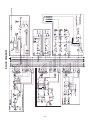
REAR PANEL CONNECTIONS
12
(49) L, R, MONO INSERT
These 1/4" stereo (TRS) jacks, provided on the LEFT, RIGHT and MONO channels, allow an
external device to be inserted into the signal path, pre-MASTER FADER. The tip carries the
signal being sent and the ring is the signal return. A switch in the jack connects the send to
the return if no plug is inserted. The signal must be returned to this jack when this feature is
used. Failure to return the signal will result in no output.
(50) L, R, MONO UNBAL (UNBALANCED OUTPUT)
These 1/4" jacks allow output of an unbalanced signal and are provided for the LEFT, RIGHT
and MONO channels.
(51) L, R, MONO BAL (BALANCED OUTPUT)
These XLR connectors allow output of a balanced signal and are also provided for the LEFT,
RIGHT and MONO channels. The unbalanced and balanced outputs can be used
simultaneously, but both output levels are controlled by the corresponding MASTER FADER.
(52) RETURN INPUTS
These 1/4" balanced (TRS) high-impedance inputs can be used as stereo or individual
returns. Designed for effects return, they can also be used as additional stereo inputs. The
MONO/LEFT input provides signal to both inputs if no connector is attached to the RIGHT
jack. The tip is the positive input for both balanced and unbalanced use.
RIGHT
OUT
LEFT
OUT
(BAL)(BAL)(BAL)
(UNBAL)
MONO
OUT
(UNBAL) (UNBAL)
MONO/
LEFT
T=IN
R=OUT
SUB 1
OUT
COMP 1
I/O
RETURN 1
RIGHT
INSERT
(TRS)
INSERT
(TRS)
INSERT
(TRS)
70 WATTS
100VAC -240VAC
RIGHT
LEFT
MONO
AUX 2
OUT
(BAL)
(UNBAL)
AUX 1
OUT
(BAL)
(UNBAL)
AUX 3
OUT
(BAL)
(UNBAL)
AUX 4
OUT
(BAL)
AUX 5
OUT
(UNBAL)
AUX 6
OUT
(UNBAL)
T=IN
R=OUT
SUB 2
OUT
COMP 2
I/O
T=IN
R=OUT
SUB 3
OUT
COMP 3
I/O
T=IN
R=OUT
SUB 4
OUT
COMP 4
I/O
RETURN 2
MONO/
LEFT
RIGHT
(UNBAL)
POWER
50/60 Hz
(UNBAL)
(UNBAL)(UNBAL)(UNBAL)(UNBAL)
49
50
51
58
57
52
53
54
55
56

(53) COMPRESSOR I/O (INPUT/OUTPUT)
These 1/4" stereo (TRS) jacks allow the internal compressors for each SUB group to be
patched to an input channel or to an external device. The tip carries the input (return) signal
to the compressor and the ring carries the output (send).
(54) SUB OUT
These 1/4" (TRS) unbalanced outputs provide signal from the SUB groups.
(55) AUX 1 - 6 OUT (UNBALANCED)
These 1/4" (TS) jacks provide signal from the AUX buses.
(56) AUX 1 - 4 OUT (BALANCED)
These XLR connectors are provided on AUX 1–4 and provide output from those buses.
These can be used simultaneously with the unbalanced jacks (55), but both levels will be
determined by the AUX SEND LEVEL (21).
POWER
(57) REMOVABLE POWER CORD
This receptacle is for the IEC line cord (included) that provides AC power to the unit. Connect
the line cord to this connector and to a properly grounded AC supply. Damage to the
equipment may occur if an improper line voltage is used (see voltage marking on unit). Never
remove or cut the ground pin of the line cord plug. The console is supplied with a properly
rated line cord. If lost or damaged, replace this cord with one of the proper rating.
NOTE: FOR UK ONLY
If the colors of the wires in the mains lead of this unit do not correspond with the colored
markings identifying terminals in your plug, proceed as follows: (1) The wire that is colored
green and yellow must be connected to the terminal marked by the letter E, or by the earth
symbol, or colored green or green and yellow. (2) The wire that is colored blue must be
connected to the terminal that is marked with the letter N, or colored black. (3) The wire
that is colored brown must be connected to the terminal that is marked with the letter L
or colored red.
(58) POWER SWITCH
Place this switch in the “|” position to apply power to the RQ 4300. Return it to the “O”
position to turn the unit off. It is recommended that the unit be turned off while patching
and/or applying power to external equipment to be used in conjunction with the RQ 4300.
The POWER LED (48) will illuminate when power has been applied and the unit is on.
13
Page is loading ...

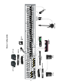
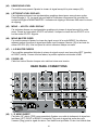
15
Q
™
215F
Q
™
231F
GPS
®
1500
GPS
®
900
(bridged)
DeltaFex
®
SP
™
2G
(right)
SP
™
2G
(left)
Mic
Out In
Comp 1 patched to Channel 1
Left, Center, Right Configuration
SP
™
2G
(center)
Direct Box
Bass Guitar

16
Stereo Configuration
Q
™
215F
GPS
®
1500
SP
™
2G
SP
™
2G
Mic
DeltaFex
®
Out In
Q
™
215F
GPS
®
900
SP
®
112M
SP
®
112M
CD Player
Mic
Wireless
Mic
Keyboard
(stereo)
Direct Box
Bass Guitar

17
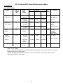
RQ
™
4324 and 4332 Sound Reinforcement Mixer
Specifications:
Input Specifications:
Function Input Z Input Input Levels Bal./ Connector
(Ohms) gain Min.** Nominal Max. Unbal.
Min. setting
Microphone 2 k Max. Gain -74 dBu -54 dBu -38 dBu Bal. XLR Pin:
(150 Ohms) (58 dB) Pin 1 (Ground)
Pin 2 (+),
Min. Gain -24 dBu -6 dBu +12 dBu Pin 3 (-)
(10 dB)
Line Input 10 k Max. Gain -54 dBu -34 dBu -18 dBu Bal. 1/4" TRS:
(10 k Ohms) (38 dB) Tip (+),
Ring (-),
Min Gain -6 dBu +14 dBu +32 dBu Sleeve (Ground)
(-10 dB)
Insert 22 k N/A -16 dBu +4 dBu +22 dBu Unbal. 1/4" TRS:
Return (0 dB) Tip Send,
Ring Return
Sleeve Ground
Stereo 20 k Max. Gain -29 dBu -9 dBu +4 dBu Unbal. 1/4" Phono
Line Input (20 dB)
Sleeve (Ground)
(RCA’s) Min. Gain -16 dBu +4 dBu +18 dBu
0 dB
(detent)
Aux Return 22 k N/A -24 dBu +4 dBu +22 dBu Unbal. 1/4" Phono
(0 dB)
0 dBu = 0.775 V (RMS)
** Minimum input level (Sensitivity) is the smallest signal that will produce nominal output (+4 dBu) with sub and
master controls set for maximum gain.
* Nominal settings are defined as all controls set at 0 dB (or 50% rotation for rotary pots) except the gain
adjustment pot, which is as specified.

18
* 0 dBu = 0.775 V (RMS)
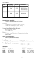
Output Specifications:
Function Minimum Output Levels, Bal./ Connector
Load Z Nominal Max. Unbal.
(Ohms)
Main L/R 600 +4 dBu +22 dBu Unbal. 1/4" Phono (Unbal);
Bal. XLR: Pin 1 Ground
Pin 2 (+)
Pin 3 (-) (Bal.)
Mono 600 +4 dBu +22 dBu Unbal. 1/4" Phono (Unbal.);
Bal. XLR: Pin 1 Ground
Pin 2 (+)
Pin 3 (-)
Sub Master 600 +4 dBu +22 dBu Unbal. 1/4" Phono
Aux Send 600 +4 dBu +22 dBu Unbal. 1/4" Phono (Unbal.);
XLR Pin 1 Ground
Pin 2 (+)
Pin 3 (-)
Channel 600 +4 dBu +22 dBu Unbal. 1/4" TRS: Tip Send,
Insert Send Ring Return,
Sleeve Ground
Headphone 8 +4 dBu +22 dBu Unbal. 1/4" TRS: Tip Left
(no load) Ring Right
Sleeve Ground
Gain:
Mic Input Gain Adj Range: 10 dB to 58 dB
Mic Input to Sub Output 78 dB (Max Gain)
Mic lnput Longest Path 88 dB (Max Gain)
Line Input Gain Adj Range: -10 dB to 38 dB
Line Input to Sub Output 58 dB (Max Gain)
Line Input Longest Path 68 dB (Max Gain)
Stereo Line Input Gain Adj Range -60 dB to 10 dB
Stereo Line Input to Sub Output 30 dB (Max Gain)
Stereo Line Input Longest Path 40 dB (Max Gain)
Aux Return to Sub Output 28 dB (Max Gain)
Aux Return Longest Path 38 dB (Max Gain)
Frequency Response:
Mic Input to L-R Output 20 Hz to 50 kHz +0 dB / -1 dB
Stereo Input to L-R Output 20 Hz to 30 kHz +0 dB / -1 dB
Total Harmonic Distortion (THD):
< 0.007% 20 Hz to 20 kHz Mic to L-R output at Nominal Level (20 Hz - 80 kHz BW)

19
Hum and Noise:
Output Residual Noise S/N Ratio Test Conditions
Ref: 0 dBu
Master L/R -105 dBu 109 dB All Faders Down
Mono
-90 dBu 94 dB Master Fader Nominal,
Channel Faders Down,
All Channels Assigned
Submaster -98 dBu 102 dB All Faders Down
-88 dBu 92 dB Submaster Fader
Nominal, Channel
Faders Down,
All Channels Assigned
(Hum and Noise Measurements: 22 Hz to 22 KHz BW)
Equivalent Input Noise (EIN):
-128 dBu (Input terminated with 150 Ohms)
Crosstalk:
>90 dB Adjacent Input Channels (20 Hz - 20 kHz)
>70 dB Left to Right Outputs (20 Hz - 20 kHz)
Common Mode Rejection Ratio (Mic Input):
50 dB min (20 Hz - 20 kHz)
70 dB typ @ 1 kHz
Meters:
L/R Master and all Submasters = 12 segment, peak reading
(0 dB= +4 dBu)
Signal / Overload Indicators:
Red LED lights 2 dB below clipping
Lamp Power:
12 VDC @ 350mA per connector, or 12VDC @ 700mA total maximum load
Power Requirements:
DOM: 100 VAC –240 VAC 50/60 Hz 70 Watts Nominal, 24 chan
80 Watts Nominal, 32 chan
RQ
™
4324
Height: 8.9" (226 mm)
Width: 36.6" (930 mm)
Depth: 19.5" (495 mm)
Weight: 36 lbs. (16.4 kg)
RQ
™
4332
Height: 8.9" (226 mm)
Width: 44.6" (1132 mm)
Depth: 19.5" (495 mm)
Weight: 48 lbs. (21.8 kg)
Dimensions:
Page is loading ...
Page is loading ...
Page is loading ...
Page is loading ...
Page is loading ...
Page is loading ...

CARACTERÍSTICAS Y CONTROLES DE LA SECCIÓN MAESTRA
ENVÍOS AUXILIARES
(21) NIVEL
Este control ajusta el nivel de salida de las varias mezclas auxiliares y es ajustable desde
cero entrada (– ∞) a +10 dB.
26
10
6
12
2
4
8
0
10
6
12
2
4
8
0
10
6
12
2
4
8
0
DYNAMICS
MONO
AUX
1
AUX
2
LEVEL
LR
CLIP
0
BAL/
PAN
33
27
21
15
9
6
3
3
6
9
AUX
1
AUX
2
LEVEL
BAL/
PAN
LR
MASTER
10
6
3
0
6
12
30
20
1
AFL
MUTE
RIGHT
MONO
LEFT
CLIP
+6
0
-20
SUB 1
2
AFL
MUTE
RIGHT
MONO
LEFT
CLIP
+6
0
-20
SUB 2
3
AFL
MUTE
RIGHT
MONO
LEFT
CLIP
+6
0
-20
SUB 3
4
AFL
MUTE
RIGHT
MONO
LEFT
CLIP
+6
0
-20
SUB 4
10
6
3
0
6
12
20
30
AFL
CLIP
0
33
27
21
15
9
6
3
3
6
9
CLIP
0
33
27
21
15
9
6
3
3
6
9
CLIP
0
33
27
21
15
9
6
3
3
6
9
MONO
AFL/PFL ACTIVE
RETURN
1
RETURN
2
1/2 3/4
L/R
MONO
1/2 3/4
L/R MONO
HEADPHONE LEVEL
LOW CUT LOW CUT
HEADPHONE
(150 Hz) (150 Hz)
TM
POWER
(+48V)
1-16
17-24
PHANTOM
POWER
MUTE/
PEAK
MUTE/
PEAK
SIG/
AFL
THRESHOLD
(dB)
0 dBu (INPUT)
GAIN
(dB)
LINK 1/2
THRESHOLD
(dB)
0 dBu (INPUT)
GAIN
(dB)
THRESHOLD
(dB)
0 dBu (INPUT)
GAIN
(dB)
THRESHOLD
(dB)
0 dBu (INPUT)
GAIN
(dB)
LINK 3/4
COMP 1 COMP 2 COMP 3 COMP 4
12
9
6
3
1
12
9
6
3
1
12
9
6
3
1
12
9
6
3
1
GAIN
REDUCTION
GAIN
REDUCTION
GAIN
REDUCTION
GAIN
REDUCTION
COMPRESSOR I/O
SUBGROUP
EXTERNAL
COMPRESSOR I/O
SUBGROUP
EXTERNAL
COMPRESSOR I/O
SUBGROUP
EXTERNAL
COMPRESSOR I/O
SUBGROUP
EXTERNAL
AUX
SEND 3
LEVEL
dB
10
0
5
3
3
40
15
6
AUX
SEND 2
LEVEL
dB
10
0
5
3
3
40
15
6
AUX
SEND 1
LEVEL
dB
10
0
5
3
3
40
15
6
AUX
SEND 6
LEVEL
dB
10
0
5
3
3
40
15
6
AUX
SEND 5
LEVEL
dB
10
0
5
3
3
40
15
6
AUX
SEND 4
LEVEL
10
6
3
0
6
12
30
20
10
6
3
0
6
12
30
20
10
6
3
0
6
12
30
20
10
6
3
0
6
12
30
20
10
6
3
0
6
12
20
30
dB
10
0
5
3
3
40
15
6
dB
10
0
5
3
3
40
15
6
dB
10
0
5
3
3
40
15
6
C
dB
10
0
5
3
3
40
15
6
dB
10
0
5
3
3
40
15
6
dB
10
0
5
3
3
40
15
6
9
5
010
1
8
2
37
64
SIG/
AFL
dB
10
0
5
3
3
40
15
6
-30 OFF
-5
-25 +15
-15 +5
-30 OFF
-5
-25 +15
-15 +5
-30 OFF
-5
-25 +15
-15 +5
-30 OFF
-5
-25 +15
-15 +5
R
L
R
L
C
MUTE/
PEAK
MUTE/
PEAK
MUTE/
PEAK
MUTE/
PEAK
MUTE/
PEAK
MUTE/
PEAK
SIG/
AFL
SIG/
AFL
SIG/
AFL
SIG/
AFL
SIG/
AFL
SIG/
AFL
10
6
12
2
4
8
0
10
6
3
0
6
12
30
20
AUXILIARY MASTER
DESIGNED IN U.S.A.
DYNAMICS
21
22
23
24
25
26
27
28
31
33
32
29
30
34
37
39
42
43
38
40
35
41
36
44
47
45
48
46
SECCIÓN MAESTRA
Page is loading ...
Page is loading ...
Page is loading ...
Page is loading ...
Page is loading ...
Page is loading ...
Page is loading ...
Page is loading ...
Page is loading ...
Page is loading ...
Page is loading ...
Page is loading ...
Page is loading ...
Page is loading ...
Page is loading ...
Page is loading ...
Page is loading ...
Page is loading ...
Page is loading ...
Page is loading ...
Page is loading ...
Page is loading ...
Page is loading ...
Page is loading ...
Page is loading ...
Page is loading ...
Page is loading ...
Page is loading ...
Page is loading ...
Page is loading ...
Page is loading ...

58
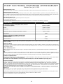
PEAVEY ELECTRONICS CORPORATION LIMITED WARRANTY
Effective Date: July 1, 1998
What This Warranty Covers
Your Peavey Warranty covers defects in material and workmanship in Peavey products purchased and serviced in the U.S.A. and Canada.
What This Warranty Does Not Cover
The Warranty does not cover: (1) damage caused by accident, misuse, abuse, improper installation or operation, rental, product modification or neg-
lect; (2) damage occurring during shipment; (3) damage caused by repair or service performed by persons not authorized by Peavey; (4) products on
which the serial number has been altered, defaced or removed; (5) products not purchased from an Authorized Peavey Dealer.
Who This Warranty Protects
This Warranty protects only the original retail purchaser of the product.
How Long This Warranty Lasts
The Warranty begins on the date of purchase by the original retail purchaser. The duration of the Warranty is as follows:
Product Category Duration
Guitars/Basses, Amplifiers, Pre-Amplifiers, Mixers, Electronic
Crossovers and Equalizers 2 years *(+ 3 years)
Drums 2 years *(+ 1 year)
Enclosures 3 years *(+ 2 years)
Digital Effect Devices and Keyboard and MIDI Controllers 1 year *(+ 1 year)
Microphones 2 years
Speaker Components (incl. speakers, baskets, drivers,
diaphragm replacement kits and passive crossovers)
and all Accessories 1 year
Tubes and Meters 90 days
[*Denotes additional warranty period applicable if optional Warranty Registration Card is completed and returned to Peavey by original retail purchaser within
90 days of purchase.]
What Peavey Will Do
We will repair or replace (at Peavey's discretion) products covered by warranty at no charge for labor or materials. If the product or component must
be shipped to Peavey for warranty service, the consumer must pay initial shipping charges. If the repairs are covered by warranty, Peavey will pay the
return shipping charges.
How To Get Warranty Service
(1) Take the defective item and your sales receipt, or other proof of date of purchase, to your Authorized Peavey Dealer or Authorized Peavey
Service Center.
OR
(2) Ship the defective item, prepaid, to Peavey Electronics Corporation, International Service Center, 412 Highway 11 & 80 East, Meridian, MS 39301
or Peavey Canada Ltd., 95 Shields Court, Markham, Ontario, Canada L3R 9T5. Include a detailed description of the problem, together with a copy of
your sales receipt or other proof of date of purchase as evidence of warranty coverage. Also provide a complete return address.
Limitation of Implied Warranties
ANY IMPLIED WARRANTIES, INCLUDING WARRANTIES OF MERCHANTABILITY AND FITNESS FOR A PARTICULAR PURPOSE, ARE LIMITED
IN DURATION TO THE LENGTH OF THIS WARRANTY.
Some states do not allow limitations on how long an implied warranty lasts, so the above limitation may not apply to you.
Exclusions of Damages
PEAVEY'S LIABILITY FOR ANY DEFECTIVE PRODUCT IS LIMITED TO THE REPAIR OR REPLACEMENT OF THE PRODUCT, AT PEAVEY’S
OPTION. IF WE ELECT TO REPLACE THE PRODUCT, THE REPLACEMENT MAY BE A RECONDITIONED UNIT. PEAVEY SHALL NOT BE
LIABLE FOR DAMAGES BASED ON INCONVENIENCE, LOSS OF USE, LOST PROFITS, LOST SAVINGS, DAMAGE TO ANY OTHER EQUIPMENT
OR OTHER ITEMS AT THE SITE OF USE, OR ANY OTHER DAMAGES WHETHER INCIDENTAL, CONSEQUENTIAL OR OTHERWISE, EVEN IF
PEAVEY HAS BEEN ADVISED OF THE POSSIBILITY OF SUCH DAMAGES.
Some states do not allow the exclusion or limitation of incidental or consequential damages, so the above limitation or exclusion may not
apply to you.
This Warranty gives you specific legal rights, and you may also have other rights which vary from state to state.
If you have any questions about this warranty or service received or if you need assistance in locating an Authorized Service Center, please contact
the Peavey International Service Center at (601) 483-5365 / Peavey Canada Ltd. at (905) 475-2578.
Features and specifications subject to change without notice.

59
IMPORTANT SAFETY INSTRUCTIONS
WARNING: When using electric products, basic cautions should always be followed, including the following:
1. Read these instructions.
2. Keep these instructions.
3. Heed all warnings.
4. Follow all instructions.
5. Do not use this apparatus near water. For example, near or in a bathtub, swimming pool, sink, wet basement, etc.
6. Clean only with a damp cloth.
7. Do not block any of the ventilation openings. Install in accordance with manufacturer’s instructions. It should not be placed flat against a wall
or placed in a built-in enclosure that will impede the flow of cooling air.
8. Do not install near any heat sources such as radiators, heat registers, stoves or other apparatus (including amplifiers) that produce heat.
9. Do not defeat the safety purpose of the polarized or grounding-type plug. A polarized plug has two blades with one wider than the other. A
grounding type plug has two blades and a third grounding plug. The wide blade or third prong is provided for your safety. When the provided
plug does not fit into your inlet, consult an electrician for replacement of the obsolete outlet. Never break off the grounding. Write for our free
booklet “Shock Hazard and Grounding”. Connect only to a power supply of the type marked on the unit adjacent to the power supply cord.
10. Protect the power cord from being walked on or pinched, particularly at plugs, convenience receptacles, and the point they exit from the
apparatus.
11. Only use attachments/accessories provided by the manufacturer.
12. Use only with a cart, stand, tripod, bracket, or table specified by the manufacturer, or sold with the apparatus. When a cart is used, use caution
when moving the cart/apparatus combination to avoid injury from tip-over.
13. Unplug this apparatus during lightning storms or when unused for long periods of time.
14. Refer all servicing to qualified service personnel. Servicing is required when the apparatus has been damaged in any way, such as power-
supply cord or plug is damaged, liquid has been spilled or objects have fallen into the apparatus, the apparatus has been exposed to rain or
moisture, does not operate normally, or has been dropped.
15. If this product is to be mounted in an equipment rack, rear support should be provided.
16. Exposure to extremely high noise levels may cause a permanent hearing loss. Individuals vary considerably in susceptibility to noise-induced
hearing loss, but nearly everyone will lose some hearing if exposed to sufficiently intense noise for a sufficient time. The U.S. Government’s
Occupational and Health Administration (OSHA) has specified the following permissible noise level exposures:
Duration Per Day In Hours Sound Level dBA, Slow Response
890
692
495
397
2 100
1 1/2 102
1 105
1/2 110
1/4 or less 115
According to OSHA, any exposure in excess of the above permissible limits could result in some hearing loss. Ear plugs or protectors to the ear
canals or over the ears must be worn when operating this amplification system in order to prevent a permanent hearing loss, if exposure is in excess
of the limits as set forth above. To ensure against potentially dangerous exposure to high sound pressure levels, it is recommended that all persons
exposed to equipment capable of producing high sound pressure levels such as this amplification system be protected by hearing protectors while
this unit is in operation.
SAVE THESE INSTRUCTIONS!
Page is loading ...
-
 1
1
-
 2
2
-
 3
3
-
 4
4
-
 5
5
-
 6
6
-
 7
7
-
 8
8
-
 9
9
-
 10
10
-
 11
11
-
 12
12
-
 13
13
-
 14
14
-
 15
15
-
 16
16
-
 17
17
-
 18
18
-
 19
19
-
 20
20
-
 21
21
-
 22
22
-
 23
23
-
 24
24
-
 25
25
-
 26
26
-
 27
27
-
 28
28
-
 29
29
-
 30
30
-
 31
31
-
 32
32
-
 33
33
-
 34
34
-
 35
35
-
 36
36
-
 37
37
-
 38
38
-
 39
39
-
 40
40
-
 41
41
-
 42
42
-
 43
43
-
 44
44
-
 45
45
-
 46
46
-
 47
47
-
 48
48
-
 49
49
-
 50
50
-
 51
51
-
 52
52
-
 53
53
-
 54
54
-
 55
55
-
 56
56
-
 57
57
-
 58
58
-
 59
59
-
 60
60


Peavey RQ 4300 Series User manual
- Category
- DJ controllers
- Type
- User manual
Ask a question and I''ll find the answer in the document
Finding information in a document is now easier with AI
in other languages
- français: Peavey RQ 4300 Series Manuel utilisateur
- español: Peavey RQ 4300 Series Manual de usuario
- Deutsch: Peavey RQ 4300 Series Benutzerhandbuch
Related papers
-
Peavey RQ 2300 User manual
-
-
-
-
-
-
-
-
Peavey PV 6 User manual
-
Other documents
-
Rolls RM203X User manual
-
Mackie 2404VLZ4 24 Channel 4 Bus Mixer User manual
-
Mackie 1642-VLZ3 User manual
-
-
Mackie 1642 User manual
-
-
-
-
-