2 Craftsman.com
Índice de contenidos
Descripción del equipo..................... 2
Características y controles .................. 5
Operación .............................. 8
Mantenimiento ......................... 13
Almacenamiento ........................ 16
Declaración de cumplimiento de la FCC y del IC . 16
Solución de problemas/Especificaciones ....... 17
Garantía . . . . . . . . . . . . . . . . . . . . . . . . . . . . . . 18
Registre su producto
Con el fin de garantizar la cobertura de la garantía de
forma oportuna y completa, registre su producto en línea
en www.Craftsman.com/registration.
Símbolos y sus significados
Señal Advertencias
PELIGRO
Indica un riesgo que, si no se evita,
ocasionará la muerte o lesiones graves.
ADVERTENCIA
Indica un riesgo que, si no se evita,
podría ocasionar la muerte o lesiones
graves.
PRECAUCIÓN
Indica un riesgo que, si no se evita,
podría ocasionar lesiones menores o
moderadas.
AVISO
Hace referencia a una práctica no
relacionada con una lesión física.
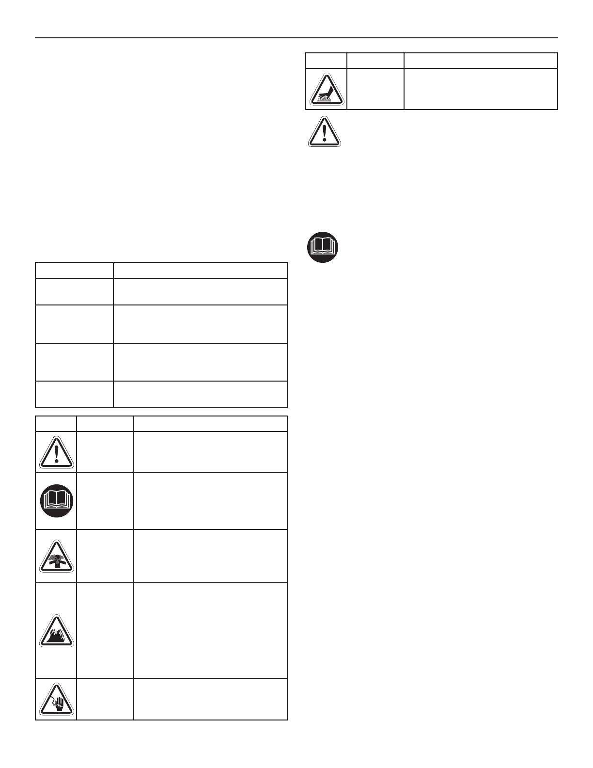
Símbolo Nombre Explicación
Símbolo de
alerta de
seguridad
Indica un posible riesgo para su
integridad física.
Manual del
operador
La omisión de las advertencias,
las instrucciones y el manual
del operador podría redundar
en lesiones graves o incluso la
muerte.
Gases
tóxicos
La descarga de escape del motor
contiene monóxido de carbono,
un gas tóxico que mata en
cuestión de minutos. No puede
olerse ni verse.
Incendio
El combustible y sus vapores son
extremadamente inflamables, lo
que podría causar quemaduras o
incendios que conlleven lesiones
graves o la muerte.
El escape del motor puede
causar un incendio y ocasionar
lesiones graves o la muerte.
Descarga
eléctrica
El generador podría provocar
electrocución y ocasionar
lesiones graves o la muerte.
Símbolo Nombre Explicación
Superficie
caliente
El silenciador puede causar
quemaduras y lesiones graves.
¡ADVERTENCIA! Este producto puede exponerlo a
sustancias químicas, entre las que se incluyen
emisiones de escape de motor de gasolina,
reconocidas por el Estado de California como causantes de
cáncer, y monóxido de carbono, reconocido por el Estado de
California como causante de defectos de nacimiento u otros
problemas reproductivos. Para obtener más información,
visite www.P65Warnings.ca.gov.
Descripción del equipo
Lea este manual atentamente y familiarícese con
el generador para exteriores. Conozca sus
aplicaciones, sus limitaciones y cualquier riesgo
implicado. Conserve estas instrucciones originales para
futuras consultas.
El generador para exteriores es un generador de corriente
alterna (CA), accionado por motor, de campo giratorio
equipado con un regulador de voltaje. Este generador
está diseñado para suministrar energía eléctrica
para iluminación, aparatos, herramientas y motores
compatibles. El regulador de voltaje dentro del generador
está diseñado para mantener el nivel de voltaje de salida
automáticamente.
El generador portátil puede usarse para suministrar energía
eléctrica a dispositivos en exteriores usando el cables de
extensión o para restablecer temporalmente la energía
eléctrica del hogar usando una llave de transferencia. Una
llave de transferencia es un dispositivo independiente
que instala un electricista con licencia para conectar
el generador portátil con cables, mediante una toma de
bloqueo, directamente al sistema eléctrico de su hogar.
Instale una llave de transferencia de la lista lo antes
posible si el generador se usará para el restablecimiento
temporal de la energía eléctrica del hogar.
Se ha realizado el máximo esfuerzo para garantizar que la
información de este manual sea precisa y esté actualizada.
No obstante, el fabricante se reserva el derecho de modificar,
alterar o mejorar de cualquier otra forma el generador y este
documento en cualquier momento y sin previo aviso.
AVISO Si tiene alguna pregunta acerca del uso previsto,
póngase en contacto con el distribuidor autorizado. Este
equipo se ha diseñado para usarse con partes autorizadas
de Briggs & Stratton únicamente.
Conexión a tierra del sistema
El generador tiene una conexión a tierra del sistema que
conecta los componentes del marco del generador con
los terminales de tierra en las tomas de salida de CA. La
puesta a tierra del sistema está conectada al cable neutral
de CA (el cable neutral está unido al marco del generador).
Descripción del equipo


