Glacier Bay 833CW-0001 Installation guide
- Category
- Sanitary ware
- Type
- Installation guide
This manual is also suitable for

THANK YOU
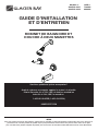
TWO-HANDLE TUB AND SHOWER FAUCET
We appreciate the trust and condence you have placed in Glacier Bay through the purchase of this tub and
shower faucet. We strive to continually create quality products designed to enhance your home. Visit us online
to see our full line of products available for your home improvement needs. Thank you for choosing Glacier Bay!
INSTALLATION AND CARE GUIDE
Questions, problems, missing parts?
Before returning to the store, call Glacier Bay Customer Service
8 a.m. - 7 p.m., EST, Monday - Friday
9 a.m. - 6 p.m., EST, Saturday
1-855-HD-GLACIER (1-855-434-5224)
HOMEDEPOT.COM
Model#
833CW-0001
833CW-0004
12/2015REV.01YOW
SKU#
716020
692422

2
Table of Contents
Safety Information ....................................2
Warranty ...................................................2
Pre-Installation .........................................3
Planning Installation ..............................3
Tools Required .......................................3
Hardware Included .................................3
Package Contents ..................................4
Installation ................................................5
8
Care and Cleaning ....................................
Service Parts .............................................9
Safety Information
Please read and understand this entire manual before
attempting to assemble, operate, or install the product.
CAUTION: Always turn off the water supply before
removing an existing faucet or replacing any part of a
faucet. Open the faucet handle to relieve water pressure
and ensure that the water is completely shut off.
Warranty
LIMITED LIFETIME WARRANTY
Glacier Bay products are manufactured with superior quality standards and workmanship and are backed by our
limited lifetime warranty. Glacier Bay products are warranted to the original consumer purchaser to be free of
defects in materials or workmanship. We will replace FREE OF CHARGE any product or parts that proves defective.
Simply, return the product / part to any of The Home Depot retail locations or call 1-855-HD-GLACIER (1-855-434-
5224) to receive the replacement item. Proof of purchase (original sales receipt) from the original consumer
purchaser must be made available for all Glacier Bay warranty claims.
This warranty excludes incidental/inconsequential damages and failures due to misuse, abuse or normal wear and
tear. This warranty excludes all industrial, commercial & business usage, whose purchasers are hereby, extended
duration of warranty.
Some states and provinces do not allow the exclusion or limitation of incidental or consequential damages, so the
above limitations may not apply to you. This warranty gives you specic legal rights and you may also have other
rights that vary from state to state and province to province. Please see a store or contact 1-855-HD-GLACIER for
more details.

3 HOMEDEPOT.COM
Please contact 1-855-HD-GLACIER for further assistance.
Pre-Installation
PLANNING INSTALLATION
Before beginning the installation of this product, ensure all parts are present. Compare parts with the Package
Contents and Hardware Included list. If any part is missing or damaged, do not attempt to install the product.
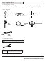
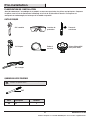
TOOLS REQUIRED
Safety
goggles
Phillips
screwdriver
Strap
wrench
HARDWARE INCLUDED
NOTE: Hardware not shown to actual size.
AA
Part Description Quantity
AA Screw 2
Measuring
tape
Adjustable
wrench
Pipe
wrench
Thread sealant tape

4
Pre-Installation (continued)
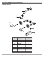
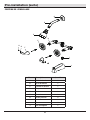
PACKAGE CONTENTS
Part Description Quantity
A
1
B Shower arm 1
C Shower head 1
D Valve body 1
E Flange 2
F Handle 2
G Set screw 2
Shower ange
H Index 2
I Plug 1
J Tub spout 1
A
B
C
D
E
H
G
I
J
F

5 HOMEDEPOT.COM
Please contact 1-855-HD-GLACIER for further assistance.
Installation
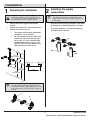
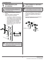
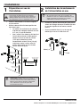
1
Preparing for installation
CAUTION: Always turn off the water supply before
removing an existing faucet or replacing any part of a
faucet. Open the faucet handle to relieve water pressure
and ensure that the water is completely shut off.
□ Shut off the water supply to the tub and
shower.
□ Verify that the hole sizes and positions of the
holes in the wall are correct
□ The shower and tub spout outlet holes
should be 1-1/4 in. diameter.
□ For the cold water inlet (the right side)
and the hot water inlet (the left side),
cut or leave a 1-3/8 in. diameter hole
(recommended size is 1-3/4 in.). The
center to center distance between the
cold and hot water inlets is 8 in.
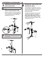
2
Installing the supply
connections
□
Wrap thread sealant tape around the valve body
(D) threads in a clockwise direction, as shown.
□
Thread the waterline (1) to the valve body (D),
and tighten with a wrench.
NOTE: Be sure to position the body (D) correctly in the
wall, with the markings "UP" facing upward. Hot water
supply lines go into the H inlet; cold water supply lines go
into the C inlet.
NOTE: Do not disassemble the cartridges during normal
installation. When reinstalling the cartridge, be sure to
insert with the limit stop (a & b) pointed inward as shown
in the diagram. This is necessary for proper operation of
the valve.
1-3/8 in. ~ 2 in.1-3/8 in. ~ 2 in.
8 in.
8 in. Min.
30 in.
Shower Only
48 in.
Tub & Shower
30 in.
Tub & Shower
48 in.
Shower Only
a
b
Cold
Hot
1
D

6
Installation (continued)
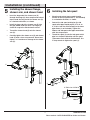
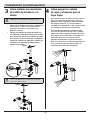
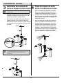
3
Installing the tub and shower
outlet connections
□ Wrap thread sealant tape around the pipe
threads in a clockwise direction, as shown.
Connect the shower (1) and tub outlet pipes (2)
to the valve body (D). Connect the pipe elbows
(3) (not included) to the ends of both pipes,
and tighten with a wrench.
□
4
Flushing the water outlets and
checking for leaks
□
□
For tub and shower combinations, turn on the
hot and cold water supply lines, allowing water
to ow from the tub spout outlet (1) until all
debris is cleared from the line. Check all
connections for leaks.
For shower only installations, turn on the hot
and cold water supply lines, allowing water
to ow from the shower outlet (2) until all
debris is cleared from the line. Pressure must
be approximately equal on both hot and cold
sides for the valve to function properly. Check
all connections for leaks.
NOTE: Do not use PEX or CPVC between the valve and
spout.
NOTE: For shower-only installation, wrap thread sealant
tape around the threads of the plug (I), and insert it into
the bottom outlet (4).
Tub
Shower
3
1
2
D
I
4
3
1
D
Shower
1
2

7 HOMEDEPOT.COM
Please contact 1-855-HD-GLACIER for further assistance.
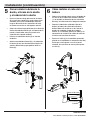
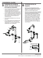
Installation (continued)
5
Installing the shower flange,
shower arm, and shower head
□ Insert the long end of the shower arm (B)
through the ange (A), then wrap thread sealant
tape around the long end of the shower arm (B)
in a clockwise direction, as shown.
□ Install the long end of the shower arm (B) into
the pipe elbow inside the wall. The ange (A)
should t snug to the nished wall surface.
□ Thread the shower head (C) onto the shower
arm (B).
□ Carefully tighten the shower arm (B) and shower
head (C) with a clean strap wrench. Do not over
tighten, as it could cause damage to the shower
arm (B).
6
Installing the tub spout
□ Wrap thread sealant tape around the pipe
threads of the tub spout outlet (1, not included)
in a clockwise direction, as shown.
Connect the tub spout outlet pipe (the tub
spout outlet pipe should project 3-7/8 in. to
4-1/16 in. from the nished wall) to the lower
pipe elbow (2, not included). Tighten the
elbows and tub spout outlet pipe connections
with the strap wrench.
□
Thread the spout (J) onto the tub spout outlet
pipe in a clockwise direction until the spout
(J) becomes ush with the nished wall. Use
a strap wrench to tighten the spout (J).
□
3-7/8 in. to 4-1/16 in.
Wall
C
B
A
2
1
J

8
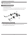
Installation (continued)
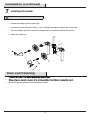
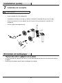
7
Installing the handle
Care and Cleaning
□
□
□ Do not use abrasive cleaners when cleaning this faucet.
□ Position the anges (E) on the valves (D).
NOTE: Before proceeding, ensure the valves are closed.
□ Position the screws (AA) on the stems (1). Use a Phillips screwdriver to tighten the screws (AA).
□ Place the handles (F) on the valves (D), and tighten the set screws (G) with the Hex wrench.
□ Attach the indexes (H).
1
D
E
AA
F
G
H

9 HOMEDEPOT.COM
Please contact 1-855-HD-GLACIER for further assistance.
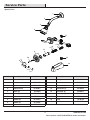
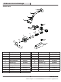
Part Description Part Number
1
RP38046*
2 Shower arm RP38047*
3 Washer RP64217
4 Shower head RP38261*
5 Index (H) RP10004
6 Index (C) RP10005
7 Set screw RP50002
8 Handle (H) RP13147*
9 Handle (C) RP13148*
10 Screw RP50178
Shower ange
Service Parts
*Specify Finish
Part Description Part Number
11
RP80387*
12 Bonnet RP70154*
13 Connector (H) RP70358
14 Connector (C) RP70359
15 Cartridge (H) RP20013
16 Cartridge (C) RP20014
17 Diverter RP70160
18 Plug RP70153
19 Spout RP33052*
Flange
1
2
4
5
6
7
8
9
10
11
12
13
14
16
15
17
18
19
3

Questions, problems, missing parts?
Before returning to the store, call Glacier Bay Customer Service
8 a.m. - 7 p.m., EST, Monday - Friday
9 a.m. - 6 p.m., EST, Saturday
1-855-HD-GLACIER (1-855-434-5224)
HOMEDEPOT.COM
Retain this manual for future use.

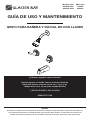
GRIFO PARA BAÑERA Y DUCHA, DE DOS LLAVES
Apreciamos la conanza que has depositado en Glacier Bay al comprar este grifo para bañera y ducha. Nos esforzamos por
crear continuamente productos de calidad diseñados para mejorar tu hogar. Visítanos en Internet para ver nuestra línea
completa de productos disponibles para las necesidades de mejoras de tu hogar. ¡Gracias por elegir a Glacier Bay!
GRACIAS
GUÍA DE USO Y MANTENIMIENTO
¿Problemas, preguntas o piezas faltantes?
Antes de regresar a la tienda, llama al servicio al cliente de
Glacier Bay de lunes a viernes entre 8 a.m. y 7 p.m. y los
sábados entre 9 a.m. y 6 p.m.(hora estándar del Este)
1-855-HD-GLACIER (1-855-434-5224)
HOMEDEPOT.COM
Modelo núm.
833CW-0001
833CW-0004
SKU núm.
716020
692422

12
Tabla de contenido
Información de seguridad ......................12
Garantía...................................................12
Pre-instalación .......................................13
.............13
Herramientas necesarias ....................13
Herrajes incluidos ................................13
Contenido del paquete .........................14
Instalación ..............................................15
Mantenimiento y limpieza ......................18
Piezas de repuesto .................................19
Información de seguridad
Lee y comprende este manual completo antes de
intentar ensamblar, operar o instalar el producto.
PRECAUCIÓN: Cierra siempre el suministro de agua
antes de quitar un grifo existente o reemplazar cualquier
pieza de un grifo. Abre la llave del grifo para liberar la
presión de agua y asegúrate de que el suministro de agua
esté completamente cerrado.
Garantía
GARANTÍA LIMITADA DE POR VIDA
Los productos de Glacier Bay están fabricados con normas y mano de obra de calidad superior y están respaldados
por nuestra garantía de por vida limitada. Glacier Bay garantiza al comprador consumidor original que sus productos
no presentan defectos materiales o de fabricación. Simplemente, devuelva el producto o pieza a
cualquiera de las tiendas minoristas de The Home Depot o llame al 1-855-HD-GLACIER (1-855-434-5224)
para recibir el artículo de reemplazo. El comprobante de compra (recibo de venta original) del comprador consumidor
original debe estar disponible para todos los reclamos de garantía de Glacier Bay.
Esta garantía excluye daños y fallos incidentales/consecuenciales debido al mal uso, abuso o desgaste normal por
el uso. Esta garantía excluye todos los usos industriales, comerciales y de negocios, a cuyos compradores se les
extiende en la presente una garantía limitada de cinco años a partir de la fecha de compra, con todos los otros
artículos de esta garantía que aplican excepto la duración de la garantía.
Algunos estados y provincias no permiten la exclusión o la limitación de los daños incidentales o consecuentes,
por lo tanto, las limitaciones y exclusiones anteriores podrían no aplicarse a su caso. Esta garantía le otorga
derechos legales especícos y también puede tener otros derechos que varían de un estado a otro. Vaya a una
tienda o llame al 1-855-HD-GLACIER para obtener más detalles.
Planicación de la instalación

AA
Llave de
correa
Cinta de
medir
Llave de
tubería
Cinta selladora
para roscas
Gafas de
seguridad
Destornillador
Phillips
Llave ajustable
Pre-instalación
PLANIFICACIÓN DE LA INSTALACIÓN
Antes de comenzar la instalación de este producto, asegúrate de que no falta ninguna pieza. Compara las piezas
con la lista de contenido del paquete y herrajes incluidos. Si falta alguna pieza o está dañada, no intentes instalar
el producto.
HERRAMIENTAS NECESARIAS
13 HOMEDEPOT.COM
Part Description Quantity
AA Tornillo 2
HERRAJES INCLUIDOS
NOTA: No se muestra el tamaño real de los herrajes.
Para obtener asistencia, llama al 1-855-HD-GLACIER.

14
Pre-instalación (continuación)
CONTENIDO DEL PAQUETE
Pieza Descripción Cantidad
A
1
B Brazo de la ducha 1
C Cabezal de la ducha 1
D Cuerpo de la válvula 1
E Brida 2
F Llave 2
G Tornillo de jación 2
Brida de la ducha
H Índice 2
I Tapón 1
J Caño de la bañera 1
A
B
C
D
E
H
G
I
J
F

15 HOMEDEPOT.COM
Instalación
□ Para la entrada de agua fría (lado derecho)
y la de agua caliente (lado izquierdo), haz o
deja un oricio de 3.5 cm (el tamaño
recomendado es 4.4 cm. La distancia entre
los centros de las entradas de agua fría y
caliente es 20.3 cm.
2
Cómo instalar las conexiones
de suministro
NOTA: Asegúrate de colocar el cuerpo (D) en la posición
correcta en la pared, con la marca "UP" hacia arriba. Las
líneas de suministro de agua caliente van en la entrada H,
las líneas de suministro de agua Fría van en la entrada C.
3.5 cm a 5.1 cm 3.5 cm a 5.1 cm
20.3 cm mín.
76.2 cm
Ducha solamente
1.22 m
Bañera y ducha
76.2 cm
Bañera y Ducha
1.22 m
Ducha solamente
20.3 cm
Fría
Caliente
NOTA: No desensambles los cartuchos durante la
instalación normal. Al reinstalar el cartucho, asegúrate de
insertarlo con el tope de límite (a y b) mirando hacia dentro
como se muestra en el diagrama. Esto es necesario para
que la válvula funcione correctamente.
Para obtener asistencia, llama al 1-855-HD-GLACIER.
1
Cómo prepararse para
la instalación
□ Cierra el suministro de agua a la bañera y a
la ducha.
□ Verica que el tamaño y la posición de los
oricios en la pared sean correctos:
□ Los oricios de salida del caño de bañera
y ducha deben ser de 3.2 cm de diámetro.
PRECAUCIÓN: Cierra siempre el suministro de agua
antes de quitar un grifo existente o reemplazar cualquier
pieza de un grifo. Abre la llave del grifo para liberar la
presión de agua y asegúrate de que el suministro de agua
esté completamente cerrado.
□
Coloca cinta selladora para roscas alrededor de
las roscas del cuerpo de la válvula (D) en el
sentido de las manecillas del reloj, como se
muestra.
□
Enrosca la línea de agua (1) en el cuerpo de la
válvula (D) y apriétala con una llave.
1
D

16
Instalación (continuación)
3
Cómo instalar las conexiones
de salida de la bañera y la
ducha
□ Coloca cinta selladora para roscas alrededor de
las roscas de la tubería en dirección de las
manecillas del reloj, tal como muestra el
diagrama anterior.
Conecta las tuberías de salida de la ducha (1)
y la tubería de salida de la bañera (2) al cuerpo
de la válvula (D). Conecta las tuberías de salida
de la ducha (1) y de la bañera (2) al cuerpo de la
válvula (D). Conecta los codos de la tubería (no
incluidos) a los extremos de ambos tubos y
aprieta con una llave.
□
4
Cómo purgar las salidas
de agua y chequear que no
haya fugas
□
□
Para combinaciones de bañera y ducha, abre las
líneas de suministro de agua fría y caliente, y
deja que el agua salga por la tubería de salida
del caño de la bañera (1) hasta que toda la
suciedad sea expulsada de la línea. Revisa todas
las conexiones para descartar ltraciones.
Para instalaciones de ducha solamente, abre
las líneas de suministro de agua fría y caliente,
y deja que el agua salga por la tubería de salida
de la ducha (2) hasta que toda la suciedad sea
expulsada de la línea. Para que la válvula
funcione correctamente, la presión del agua
debe ser la misma en la salida del agua caliente
y en la salida del agua fría. Revisa todas las
conexiones para descartar ltraciones.
NOTA: No usar PEX o CPVC entre la válvula y el caño.
NOTA: Para instalar sólo la ducha, coloca cinta selladora
de roscas alrededor de las roscas del tapón (I) e insértalo
dentro de la salida inferior (4).
Bañera
Ducha
3
1
2
D
I
4
3
1
D
Ducha
1
2

17 HOMEDEPOT.COM
Instalación (continuación)
5
Cómo instalar la brida de la
ducha, el brazo de la ducha
y el cabezal de la ducha
□ Inserta el extremo largo del brazo de la ducha
(B) a través de la brida (A) y luego coloca cinta
selladora para roscas alrededor del extremo
largo en dirección de las manecillas del reloj,
tal como se muestra en el diagrama anterior.
□ Coloca el extremo largo del brazo de la ducha (B)
dentro del codo de tubería que está dentro de la
pared. La brida debe encajar ajustada en la
supercie de la pared acabada.
□ Enrosca el cabezal de ducha (C) en el brazo
de ducha.
□ Aprieta con cuidado el brazo (B) y el cabezal de
la ducha (C) con una llave de correa limpia. No
aprietes demasiado ya que podrías dañar el
brazo (B).
6
Cómo instalar el caño de la
bañera
□ Coloca cinta selladora para roscas alrededor de
las roscas de la tubería del caño de la bañera
(1, no incluida) en dirección de las manecillas
del reloj, tal como muestra el diagrama anterior.
Conecta la tubería de salida del caño de la
bañera (la tubería de salida del caño de la
bañera debe salir de 9.8 cm a 10.3 cm de la
pared con acabado) al codo de la tubería
inferior (2, no incluido). Aprieta los codos y las
conexiones de la tubería de salida del caño de
la bañera con una llave de correa.
□
Enrosca el caño (J) en la conexión enroscada,
girando en el sentido de las manecillas del reloj
hasta que el caño quede a ras de la pared
acabada. Usa una llave de correa para apretar
el caño (J).
□
9.8 cm a 10.3 cm
Pared
Para obtener asistencia, llama al 1-855-HD-GLACIER.
C
B
A
2
1
J

□ Coloca las llaves (F) en las válvulas (D) y aprieta los tornillos de jación (G) con la llave hexagonal.
18
Instalación (continuación)
7
Cómo instalar la llave
Mantenimiento y limpieza
□ Coloca la brida (E) en la válvula (D).
NOTA: Antes de continuar, asegúrate de que las válvulas
estén cerradas.
□ Coloca los tornillos (AA) en los vástagos (1). Usa un destornillador Phillips para apretar los tornillos (AA).
□ Fija los índices (H).
□ Conserva el acabado del grifo aplicando cera no abrasiva.
□ Cuando uses limpiadores no abrasivos, enjuaga de inmediato cuando termines de limpiar el grifo.
□ No uses limpiadores abrasivos para limpiar este grifo.
1
D
E
AA
F
G
H

RP38046*
RP38047*
RP64217
RP38261*
RP10004
RP10005
RP50002
RP13147*
19 HOMEDEPOT.COM
Pieza Descripción Número de pieza
1
2 Brazo de la ducha
3 Arandela
4 Cabezal de la ducha
5
Índice (H)
6 Índice (C)
7 Tornillo de jación
8 Llave (H)
Brida de la ducha
Piezas de repuesto
*Especicar acabado
Pieza Descripción Número de pieza
Para obtener asistencia, llama al 1-855-HD-GLACIER.
1
2
4
5
6
7
8
9
10
11
12
13
14
16
15
17
18
19
3
9 Llave (C) RP13148*
10 Tornillo RP50178
11
RP80387*
12 Bonete RP70154*
13 Conector (H) RP70358
14 Conector (C) RP70359
15 Cartucho (H) RP20013
16 Cartucho (C) RP20014
17 Desviador RP70160
18 Tapón RP70153
19 Caño RP33052*
Brida

¿Problemas, preguntas o piezas faltantes?
Antes de regresar a la tienda, llama al servicio al cliente de
Glacier Bay de lunes a viernes entre 8 a.m. y 7 p.m. y los
sábados entre 9 a.m. y 6 p.m.(hora estándar del Este)
1-855-HD-GLACIER (1-855-434-5224)
HOMEDEPOT.COM
Conserva este manual para uso futuro.
Page is loading ...
Page is loading ...
Page is loading ...
Page is loading ...
Page is loading ...
Page is loading ...
Page is loading ...
Page is loading ...
Page is loading ...
Page is loading ...
-
 1
1
-
 2
2
-
 3
3
-
 4
4
-
 5
5
-
 6
6
-
 7
7
-
 8
8
-
 9
9
-
 10
10
-
 11
11
-
 12
12
-
 13
13
-
 14
14
-
 15
15
-
 16
16
-
 17
17
-
 18
18
-
 19
19
-
 20
20
-
 21
21
-
 22
22
-
 23
23
-
 24
24
-
 25
25
-
 26
26
-
 27
27
-
 28
28
-
 29
29
-
 30
30


Glacier Bay 833CW-0001 Installation guide
- Category
- Sanitary ware
- Type
- Installation guide
- This manual is also suitable for
Ask a question and I''ll find the answer in the document
Finding information in a document is now easier with AI
in other languages
Related papers
-
Glacier Bay HD873X-4004 Installation guide
-
-
-
-
-
-
-
-
-
Other documents
-
Design House 545913 Installation guide
-
-
ProFlo PF1033G2CP Installation guide
-
Jacuzzi 873W-562707 User manual
-
Miseno MNOSH425EFB Installation guide
-
-
-
-
HOMEWERKS 3010-501-bn Operating instructions
-